EP1902877A1 - Thermisches Steuerverfahren, insbesondere für die Motorkühlung und/oder Klimatisierung eines Kraftfahrzeugs und thermisches Steuerungssystem, bei dem dieses Verfahren zum Einsatz kommt - Google Patents
Thermisches Steuerverfahren, insbesondere für die Motorkühlung und/oder Klimatisierung eines Kraftfahrzeugs und thermisches Steuerungssystem, bei dem dieses Verfahren zum Einsatz kommt Download PDFInfo
- Publication number
- EP1902877A1 EP1902877A1 EP07116680A EP07116680A EP1902877A1 EP 1902877 A1 EP1902877 A1 EP 1902877A1 EP 07116680 A EP07116680 A EP 07116680A EP 07116680 A EP07116680 A EP 07116680A EP 1902877 A1 EP1902877 A1 EP 1902877A1
- Authority
- EP
- European Patent Office
- Prior art keywords
- coolant
- thermal management
- low temperature
- exchanger
- loop
- Prior art date
- Legal status (The legal status is an assumption and is not a legal conclusion. Google has not performed a legal analysis and makes no representation as to the accuracy of the status listed.)
- Withdrawn
Links
Images


Classifications
-
- B—PERFORMING OPERATIONS; TRANSPORTING
- B60—VEHICLES IN GENERAL
- B60H—ARRANGEMENTS OF HEATING, COOLING, VENTILATING OR OTHER AIR-TREATING DEVICES SPECIALLY ADAPTED FOR PASSENGER OR GOODS SPACES OF VEHICLES
- B60H1/00—Heating, cooling or ventilating devices
- B60H1/00642—Control systems or circuits; Control members or indication devices for heating, cooling or ventilating devices
- B60H1/00814—Control systems or circuits characterised by their output, for controlling particular components of the heating, cooling or ventilating installation
- B60H1/00878—Control systems or circuits characterised by their output, for controlling particular components of the heating, cooling or ventilating installation the components being temperature regulating devices
- B60H1/00885—Controlling the flow of heating or cooling liquid, e.g. valves or pumps
-
- F—MECHANICAL ENGINEERING; LIGHTING; HEATING; WEAPONS; BLASTING
- F01—MACHINES OR ENGINES IN GENERAL; ENGINE PLANTS IN GENERAL; STEAM ENGINES
- F01P—COOLING OF MACHINES OR ENGINES IN GENERAL; COOLING OF INTERNAL-COMBUSTION ENGINES
- F01P7/00—Controlling of coolant flow
- F01P7/14—Controlling of coolant flow the coolant being liquid
- F01P7/16—Controlling of coolant flow the coolant being liquid by thermostatic control
- F01P7/165—Controlling of coolant flow the coolant being liquid by thermostatic control characterised by systems with two or more loops
-
- F—MECHANICAL ENGINEERING; LIGHTING; HEATING; WEAPONS; BLASTING
- F01—MACHINES OR ENGINES IN GENERAL; ENGINE PLANTS IN GENERAL; STEAM ENGINES
- F01P—COOLING OF MACHINES OR ENGINES IN GENERAL; COOLING OF INTERNAL-COMBUSTION ENGINES
- F01P9/00—Cooling having pertinent characteristics not provided for in, or of interest apart from, groups F01P1/00 - F01P7/00
- F01P9/06—Cooling having pertinent characteristics not provided for in, or of interest apart from, groups F01P1/00 - F01P7/00 by use of refrigerating apparatus, e.g. of compressor or absorber type
-
- F—MECHANICAL ENGINEERING; LIGHTING; HEATING; WEAPONS; BLASTING
- F02—COMBUSTION ENGINES; HOT-GAS OR COMBUSTION-PRODUCT ENGINE PLANTS
- F02B—INTERNAL-COMBUSTION PISTON ENGINES; COMBUSTION ENGINES IN GENERAL
- F02B29/00—Engines characterised by provision for charging or scavenging not provided for in groups F02B25/00, F02B27/00 or F02B33/00 - F02B39/00; Details thereof
- F02B29/04—Cooling of air intake supply
- F02B29/0406—Layout of the intake air cooling or coolant circuit
- F02B29/0437—Liquid cooled heat exchangers
- F02B29/0443—Layout of the coolant or refrigerant circuit
-
- F—MECHANICAL ENGINEERING; LIGHTING; HEATING; WEAPONS; BLASTING
- F02—COMBUSTION ENGINES; HOT-GAS OR COMBUSTION-PRODUCT ENGINE PLANTS
- F02M—SUPPLYING COMBUSTION ENGINES IN GENERAL WITH COMBUSTIBLE MIXTURES OR CONSTITUENTS THEREOF
- F02M31/00—Apparatus for thermally treating combustion-air, fuel, or fuel-air mixture
- F02M31/02—Apparatus for thermally treating combustion-air, fuel, or fuel-air mixture for heating
- F02M31/04—Apparatus for thermally treating combustion-air, fuel, or fuel-air mixture for heating combustion-air or fuel-air mixture
- F02M31/10—Apparatus for thermally treating combustion-air, fuel, or fuel-air mixture for heating combustion-air or fuel-air mixture by hot liquids, e.g. lubricants or cooling water
-
- B—PERFORMING OPERATIONS; TRANSPORTING
- B60—VEHICLES IN GENERAL
- B60H—ARRANGEMENTS OF HEATING, COOLING, VENTILATING OR OTHER AIR-TREATING DEVICES SPECIALLY ADAPTED FOR PASSENGER OR GOODS SPACES OF VEHICLES
- B60H1/00—Heating, cooling or ventilating devices
- B60H1/00642—Control systems or circuits; Control members or indication devices for heating, cooling or ventilating devices
- B60H1/00814—Control systems or circuits characterised by their output, for controlling particular components of the heating, cooling or ventilating installation
- B60H1/00878—Control systems or circuits characterised by their output, for controlling particular components of the heating, cooling or ventilating installation the components being temperature regulating devices
- B60H2001/00928—Control systems or circuits characterised by their output, for controlling particular components of the heating, cooling or ventilating installation the components being temperature regulating devices comprising a secondary circuit
-
- B—PERFORMING OPERATIONS; TRANSPORTING
- B60—VEHICLES IN GENERAL
- B60H—ARRANGEMENTS OF HEATING, COOLING, VENTILATING OR OTHER AIR-TREATING DEVICES SPECIALLY ADAPTED FOR PASSENGER OR GOODS SPACES OF VEHICLES
- B60H1/00—Heating, cooling or ventilating devices
- B60H1/00642—Control systems or circuits; Control members or indication devices for heating, cooling or ventilating devices
- B60H1/00814—Control systems or circuits characterised by their output, for controlling particular components of the heating, cooling or ventilating installation
- B60H1/00878—Control systems or circuits characterised by their output, for controlling particular components of the heating, cooling or ventilating installation the components being temperature regulating devices
- B60H2001/00949—Control systems or circuits characterised by their output, for controlling particular components of the heating, cooling or ventilating installation the components being temperature regulating devices comprising additional heating/cooling sources, e.g. second evaporator
-
- F—MECHANICAL ENGINEERING; LIGHTING; HEATING; WEAPONS; BLASTING
- F01—MACHINES OR ENGINES IN GENERAL; ENGINE PLANTS IN GENERAL; STEAM ENGINES
- F01P—COOLING OF MACHINES OR ENGINES IN GENERAL; COOLING OF INTERNAL-COMBUSTION ENGINES
- F01P3/00—Liquid cooling
- F01P3/18—Arrangements or mounting of liquid-to-air heat-exchangers
- F01P2003/182—Arrangements or mounting of liquid-to-air heat-exchangers with multiple heat-exchangers
-
- F—MECHANICAL ENGINEERING; LIGHTING; HEATING; WEAPONS; BLASTING
- F01—MACHINES OR ENGINES IN GENERAL; ENGINE PLANTS IN GENERAL; STEAM ENGINES
- F01P—COOLING OF MACHINES OR ENGINES IN GENERAL; COOLING OF INTERNAL-COMBUSTION ENGINES
- F01P5/00—Pumping cooling-air or liquid coolants
- F01P5/10—Pumping liquid coolant; Arrangements of coolant pumps
- F01P2005/105—Using two or more pumps
-
- F—MECHANICAL ENGINEERING; LIGHTING; HEATING; WEAPONS; BLASTING
- F01—MACHINES OR ENGINES IN GENERAL; ENGINE PLANTS IN GENERAL; STEAM ENGINES
- F01P—COOLING OF MACHINES OR ENGINES IN GENERAL; COOLING OF INTERNAL-COMBUSTION ENGINES
- F01P2037/00—Controlling
- F01P2037/02—Controlling starting
-
- F—MECHANICAL ENGINEERING; LIGHTING; HEATING; WEAPONS; BLASTING
- F01—MACHINES OR ENGINES IN GENERAL; ENGINE PLANTS IN GENERAL; STEAM ENGINES
- F01P—COOLING OF MACHINES OR ENGINES IN GENERAL; COOLING OF INTERNAL-COMBUSTION ENGINES
- F01P2060/00—Cooling circuits using auxiliaries
- F01P2060/02—Intercooler
-
- F—MECHANICAL ENGINEERING; LIGHTING; HEATING; WEAPONS; BLASTING
- F01—MACHINES OR ENGINES IN GENERAL; ENGINE PLANTS IN GENERAL; STEAM ENGINES
- F01P—COOLING OF MACHINES OR ENGINES IN GENERAL; COOLING OF INTERNAL-COMBUSTION ENGINES
- F01P2060/00—Cooling circuits using auxiliaries
- F01P2060/08—Cabin heater
-
- F—MECHANICAL ENGINEERING; LIGHTING; HEATING; WEAPONS; BLASTING
- F01—MACHINES OR ENGINES IN GENERAL; ENGINE PLANTS IN GENERAL; STEAM ENGINES
- F01P—COOLING OF MACHINES OR ENGINES IN GENERAL; COOLING OF INTERNAL-COMBUSTION ENGINES
- F01P2060/00—Cooling circuits using auxiliaries
- F01P2060/18—Heater
-
- F—MECHANICAL ENGINEERING; LIGHTING; HEATING; WEAPONS; BLASTING
- F01—MACHINES OR ENGINES IN GENERAL; ENGINE PLANTS IN GENERAL; STEAM ENGINES
- F01P—COOLING OF MACHINES OR ENGINES IN GENERAL; COOLING OF INTERNAL-COMBUSTION ENGINES
- F01P7/00—Controlling of coolant flow
- F01P7/14—Controlling of coolant flow the coolant being liquid
- F01P7/16—Controlling of coolant flow the coolant being liquid by thermostatic control
- F01P7/162—Controlling of coolant flow the coolant being liquid by thermostatic control by cutting in and out of pumps
-
- Y—GENERAL TAGGING OF NEW TECHNOLOGICAL DEVELOPMENTS; GENERAL TAGGING OF CROSS-SECTIONAL TECHNOLOGIES SPANNING OVER SEVERAL SECTIONS OF THE IPC; TECHNICAL SUBJECTS COVERED BY FORMER USPC CROSS-REFERENCE ART COLLECTIONS [XRACs] AND DIGESTS
- Y02—TECHNOLOGIES OR APPLICATIONS FOR MITIGATION OR ADAPTATION AGAINST CLIMATE CHANGE
- Y02T—CLIMATE CHANGE MITIGATION TECHNOLOGIES RELATED TO TRANSPORTATION
- Y02T10/00—Road transport of goods or passengers
- Y02T10/10—Internal combustion engine [ICE] based vehicles
- Y02T10/12—Improving ICE efficiencies
Definitions
- the invention relates to a thermal management method, especially for motor cooling and / or air conditioning of a motor vehicle and a thermal management system using such a method.
- thermal management system comprising air conditioning circuits using a refrigerant such as carbon dioxide (CO 2 ) operating in the supercritical state, that is to say where the fluid remains mostly in the gaseous state in the air conditioning circuit.
- a refrigerant such as carbon dioxide (CO 2 ) operating in the supercritical state
- Such a circuit may in particular comprise a compressor, a gas cooler, an internal heat exchanger, an expander, an evaporator and an accumulator.
- the gas cooler which replaces the condenser of conventional air conditioning circuits, is arranged to cool the gaseous refrigerant fluid by heat exchange with either the ambient air (air / gas type heat exchanger) or with the engine coolant. or heat transfer liquid (water / gas type heat exchanger, also known under the name of Water / Gas Cooler or "WGC").
- An air conditioning circuit in which a refrigerant circulates and which comprises at least one gas cooler comprising at least two successive stages, and where each stage allows a heat exchange between a coolant (circulating in an engine cooling circuit) and the fluid refrigerant is described for example in the FR-A-2,875,743 on behalf of Valeo Thermal Systems.
- the cooling fluid is a gaseous refrigerant such as CO 2 .
- the starting point of the invention lies in the observation that the use of a water / gas exchanger in such circuits does not make it possible to use all the potential of the exchanger in a certain number of operating cases. , especially when the engine is cold. Moreover, even when the engine is hot, because of the improved efficiency of internal combustion engines, in particular diesel engines, it appears in certain conditions a deficit of energy to meet the heating needs of the passenger compartment which would penalize the comfort of the driver and the passengers. To compensate for this deficit, additional sources of heating are used such as burners, electric resistors, etc., but these additional means of course involve a large footprint, weight and extra cost.
- the invention proposes to use as a heat source the air conditioning loop, by heating the heat transfer liquid of the engine cooling circuit with the refrigerant fluid of the air conditioning circuit, this fluid being itself heated by passing through the compressor.
- the gas cooler comprises at least two successive stages, each stage allowing a heat exchange between the coolant and the coolant.
- the circulation of the coolant liquid in the first and / or second stage is reduced and / or interrupted selectively, so as to increase correspondingly the quantity of heat transferred by the coolant to the coolant flowing in the other floor.
- the heat released by the compression of the refrigerant fluid in the air conditioning circuit is used to increase the temperature of the liquid. coolant.
- the additional heat thus transferred to the latter is recovered to increase the temperature supplied to the engine (cold engine condition or the need for significant heating of the passenger compartment) and / or to circulate the thus heated liquid in a circuit loop including a charge air heater, to increase the temperature of the intake air delivered to the engine.
- the thermal management system further comprises regulating means adapted to reduce and / or selectively interrupt the circulation of the coolant in the first and / or second stage, so as to correlatively increase the quantity heat transferred by the refrigerant to the coolant circulating in the other stage.
- Figure 1 is a diagram showing a motor vehicle air conditioning circuit, traversed by a refrigerant operating in the supercritical state.
- Figure 2 is an enthalpy diagram of the refrigerant used in the circuit of Figure 1.
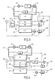
- Figure 3 illustrates in more detail the implementation of the various elements of the engine cooling circuit and air conditioning water / gas exchanger of the diagram of Figure 1, with the engine cooling loop and the various air conditioning loops and their associated elements.
- FIG. 4 illustrates an advantageous variant of the engine cooling and air conditioning system with a water / gas exchanger according to the present invention.
- FIG. 5 illustrates a second embodiment of the engine / air conditioning cooling system with a water / gas exchanger according to the present invention.
- FIG. 6 illustrates a variant of the circuit represented in FIG.
- Figures 1 and 3 illustrate a motor vehicle air conditioning system using a refrigerant operating in the supercritical state such as CO 2 , where the temperature of the refrigerant is lowered by heat exchange with the engine coolant.
- a refrigerant operating in the supercritical state such as CO 2
- the circuit comprises a compressor 10, for example an externally controlled compressor controlled by a control electronics 12.
- the compressed refrigerant then passes through a gas cooler 14 comprising one or more successive exchangers, namely three exchangers E1, E2 and E3 mounted in series in the example shown.
- the fluid passes through an internal exchanger 16, then is expanded in a pressure reducer 18, for example an expansion valve controlled also by the control electronics 12.
- the fluid thus expanded is led to a heat exchanger 20 ensuring an evaporator function, then to an accumulator 22 and the internal exchanger 16, before being recycled to the compressor 10.
- the gas cooler 14 comprises, for example, as illustrated in FIG. 1, a series of three heat exchangers E1, E2, E3 operating respectively at high temperature, low temperature and very low temperature, these three exchangers making it possible to define three cooling stages.
- the first heat exchanger E 1 defining the first cooling stage is a water / gas exchanger using as engine cooling source the engine coolant, generally water added with an antifreeze (glycoled water) or similar liquid.
- the low-temperature exchanger E2 defining the second cooling stage also uses the engine coolant as a cold source, via a loop distinct from the loop supplying the exchanger E1.
- the very low temperature exchanger E3 defining the third cooling stage can also use as cool source the engine coolant, via a separate loop of the loop feeding the exchanger E1, or operate by contact with ambient air taken outside the vehicle; in simplified embodiments, the third stage E3 of the cooler may be omitted.
- the high temperature (the "temperature” in question being understood as the temperature of the coolant circulating in the water / gas exchanger) is usually of the order of 80 to 100 ° C (typically 90 ° C), the low temperature of the order of the order 50 at 70 ° C (typically 60 ° C), and the very low temperature of the order of 30 to 60 ° C (typically 50 ° C) in the case of a water / gas exchanger using the engine coolant, or a temperature depending on the ambient air in the case of an air / gas exchanger.
- FIG. 2 shows the refrigerant state diagram for the different operating phases, with the enthalpy H on the abscissa and the P pressure on the ordinate.
- the first exchanger E1 of the gas cooler is part of a cooling loop 24 of the motor M, called the high temperature loop (HT).
- HT high temperature loop
- the second exchanger E2 is part of a cooling loop 26 called low temperature loop (LV), separate from the cooling loop of the engine although using the same coolant.
- the low-temperature heat exchanger (E2) on the hot side is fed with the coolant to be cooled from the high-temperature heat exchanger (E1), and on the cold side with coolant circulating in the low-temperature cooling radiator (38).
- the third exchanger E3 is part of a cooling loop 28, said loop at very low temperature (TBT), which is also distinct from the engine cooling loop although using the same heat transfer liquid.
- TBT very low temperature
- the heat exchanger is supplied with very low temperature on the hot side by the coolant to be cooled from the low temperature heat exchanger (E2), and on the cold side by coolant circulating in a very low temperature cooling radiator (42).
- the third heat exchanger E3 can be omitted, the refrigerant is then simply cooled by two exchangers both traveled by the engine coolant.
- the refrigerant circulates in a pipe 30 of the circuit illustrated in FIG. 1, which is a high-pressure gas pipe (that is to say capable of withstanding typical pressures of the order of 450 bars), passing successively through the three heat exchangers E1, E2 and E3 in the direction indicated by the arrows.
- a pipe 30 of the circuit illustrated in FIG. 1 which is a high-pressure gas pipe (that is to say capable of withstanding typical pressures of the order of 450 bars)
- the engine coolant M hereinafter referred to as "coolant”, which is typically water with antifreeze, is set in motion in the loop 24 by a circulation pump 32, and it also passes through a engine cooling radiator 34.
- the second exchanger E2 is part of the low temperature cooling loop 26, which is independent of the cooling loop 24 of the engine, but which is also traversed by the heat transfer liquid.
- Loop 26 has its own circulation pump 36, called the second circulation pump, and a low-temperature cooling radiator 38.
- the third exchanger E3 is part of the very low temperature cooling loop 28 which is independent of the engine cooling loop 24 and (at least in the embodiment illustrated in FIG. 3) also independent of the low temperature loop 26.
- the loop 28 also has its own auxiliary pump pump 40 called third pump, and it comprises a cooling radiator 42 operating at very low temperature.
- the engine cooling circuit also comprises a thermostat 44 controlling the flow of the heat transfer fluid in the radiator 34, for example by means of a temperature controlled valve prohibiting or reducing the passage of the coolant in the radiator 34 until the engine has reached full operating temperature.
- This thermostat 44 does not penalize the temperature rise of the engine at startup; on the other hand, it does not prevent the passage of the coolant in the heat exchanger E1, which therefore remains traversed by the coolant whatever the state of the thermostat 44.
- the above cooling and air conditioning equipment may also include a charge air heater or "RAS” 46, also known as Water / Charged-Air Cooler or “WCAC”, which is generally used for cooling. air-powered supercharging devices, but that would be used here as a heat exchanger to yield heat to the engine intake air.
- RAS charge air heater
- WCAC Water / Charged-Air Cooler
- the low temperature loop 26 finally comprises an expansion tank 48 for absorbing the variations in volume of the liquid as a function of temperature.
- the invention proposes a management method in which the circulation of the coolant liquid is reduced and / or selectively interrupted in the first and / or second stage (or in other words in the heat exchangers E1 and / or E2), so as to increase correspondingly the amount of heat transferred by the refrigerant to the coolant circulating in the other stage.
- the known circuit of FIG. 3 remains structurally configured as illustrated, but its operation is modified when it is desired to respond to additional heating requirements by the motor; that is to say a faster increase of the engine temperature and / or a need for significant heating of the passenger compartment.
- the low temperature loops 26 and very low temperature 28 are rendered inactive.
- the circulation of the coolant liquid is selectively interrupted in the respective low temperature and very low temperature radiators 42.
- the circulation of the coolant liquid remains ensured in the exchanger E1, by means of the motor circulation pump 32 (of which the second and third pumps 36 and 40 of the low-temperature loops 26 and the very low temperature circuits 28 are independent) , which continues to work.
- This modification will have the effect of modifying the state diagram of the coolant which will no longer be cooled in the exchangers E2 and E3 because of the stopping of the second and third circulation pumps 36 and 40.
- the flow rate of the second clean circulation pump 36 is controlled to reduce and / or interrupt the flow rate of the second own circulation pump 36 so as to reduce the heat exchange in the low temperature exchanger.
- the state diagram becomes that illustrated in B or C in FIG. 2. These two diagrams respectively correspond to an expansion at 40 bars or 50 bars, a value that can be adjusted by appropriate adjustment of the controlled expansion valve. .
- the coolant is no longer cooled by the exchanger E1 (segment B 1 B 2 , the segment B 2 B 3 corresponding to the work of the internal heat exchanger 16), it does not produce enough cold.
- the "air-conditioning" mode is thus transformed into “heating” mode, with transfer of heat from the coolant to the coolant, via the high-temperature heat exchanger E1.
- the heat exchange is essentially through the exchanger E1, which cools the refrigerant and heats the engine water.
- the work of the compressor of the air conditioning circuit is used to heat the engine via the exchanger E1.
- the refrigerant temperature remains positive (of the order of + 5 ° C), which allows to preheat the ambient air when the outside temperature is very low, by example an outside temperature of the order of -20 ° C.
- This preheated air is sent to the radiator (not shown) for heating the passenger compartment of the vehicle to reach the desired temperature in the passenger compartment.
- Figure 4 illustrates an embodiment of the invention for further ensuring a heating of the engine intake air.
- the configuration illustrated in FIG. 4 provides a regulator 50, such as a temperature-controlled valve, for selectively short-circuiting the inlet and the outlet of the low-temperature cooling radiator 38 to force the coolant of the low temperature loop 26 to circulate in the charge air cooler 46, mounted in series in the loop between the radiator 38 and the exchanger E2.
- the second pump 36 which in this case remains in operation, ensures the circulation of the coolant completely or partially in the charge air heater 46 instead of crossing the cooling radiator 38.
- the refrigerant flowing in the exchanger E2 may then transfer some of its heat to the coolant circulating in the loop 26, thus to the intake air of the engine via the heater 46.
- the operation of the regulating member 50 can be progressive (thermostat or proportional valve), or abrupt (valve type "all or nothing").
- the control of this unit can be operated by the vehicle's on-board computer according to the signals delivered by one or more external sensors or probes.
- Figures 5 and 6 illustrate a second form of implementation of the invention, which can be envisaged both as a variant and in addition to that just described.
- an additional regulation means 54 makes it possible to vary the flow rate of the coolant passing through the high temperature exchanger E1.
- this will have the effect of reducing or even canceling the flow rate in this exchanger, with the result of further increasing the heat transfer in the low temperature exchanger E2 and, consequently, the amount of heat transferred to the engine intake air by the charge air heater 46.
- the flow rate of the coolant in the low temperature loop 26 is adjusted by a regulator member 52 arranged in this loop between the low temperature cooling radiator 38 and the exchanger E2.
- the charge air heater 46 is arranged in series with the low temperature radiator 38.
- the two loops temperature low 26 and very low temperature 28 are interdependent: the heat transfer liquid is driven by a single pump 36 called common pump, and the respective inputs of the low temperature cooling radiators 38 and very low temperature 42 are connected in parallel.
- the coolant entrained by the common pump 36 thus passes through the charge air heater 46, then is directed to the two low-temperature cooling radiators 38 and very low temperature 42.
- the respective flow rate in these two radiators will be modified, and correspondingly the flow rate in the respective associated exchangers E2 and E3, thus making it possible to adjust the heat transfer for the heating of the engine intake air. It is thus possible to be able to increase in the second loop the relative flow rate of the coolant passing through the charge air heater 46 relative to that of the liquid passing through the low temperature cooling radiator 38.
- the two loops 26 and 28 are independent (as in the configurations of FIGS. 3 and 4), and the regulation member 56 of the low temperature loop 26 ensures, as necessary, the setting short circuit of the low temperature radiator 38.
- the heat transfer liquid is entrained in the third loop by a third auxiliary auxiliary circulation pump 40, and the flow rate of the third auxiliary auxiliary circulation pump 40 is controlled to reduce and / or interrupt the flow of the third circulation pump clean so as to reduce the heat exchange in the exchanger very low temperature.
- This configuration is similar to that illustrated in FIG. 4, with the difference that it is here possible to further increase the heat transfer to the charge air heater 46 by reducing the heat transfer in the high temperature heat exchanger E1.
Landscapes
- Engineering & Computer Science (AREA)
- Mechanical Engineering (AREA)
- Chemical & Material Sciences (AREA)
- Combustion & Propulsion (AREA)
- General Engineering & Computer Science (AREA)
- Physics & Mathematics (AREA)
- Thermal Sciences (AREA)
- Air-Conditioning For Vehicles (AREA)
Applications Claiming Priority (1)
| Application Number | Priority Date | Filing Date | Title |
|---|---|---|---|
| FR0608240 | 2006-09-20 |
Publications (1)
| Publication Number | Publication Date |
|---|---|
| EP1902877A1 true EP1902877A1 (de) | 2008-03-26 |
Family
ID=37909817
Family Applications (1)
| Application Number | Title | Priority Date | Filing Date |
|---|---|---|---|
| EP07116680A Withdrawn EP1902877A1 (de) | 2006-09-20 | 2007-09-18 | Thermisches Steuerverfahren, insbesondere für die Motorkühlung und/oder Klimatisierung eines Kraftfahrzeugs und thermisches Steuerungssystem, bei dem dieses Verfahren zum Einsatz kommt |
Country Status (1)
| Country | Link |
|---|---|
| EP (1) | EP1902877A1 (de) |
Cited By (4)
| Publication number | Priority date | Publication date | Assignee | Title |
|---|---|---|---|---|
| EP1637709A3 (de) * | 2004-09-17 | 2010-04-14 | Behr GmbH & Co. KG | Kühlkreislauf für Kraftfahrzeuge |
| WO2014166713A1 (de) * | 2013-04-09 | 2014-10-16 | Bayerische Motoren Werke Aktiengesellschaft | Verfahren zum betreiben eines co2-kältemittelkreislaufs sowie co2-kältemittelkreislauf |
| EP2835514A1 (de) * | 2013-08-07 | 2015-02-11 | Mahle International GmbH | Kühlsystem und zugehöriges Betriebsverfahren |
| CN109927534A (zh) * | 2019-03-20 | 2019-06-25 | 天津大学 | 一种混合动力重型载货汽车的热管理系统及控制方法 |
Citations (3)
| Publication number | Priority date | Publication date | Assignee | Title |
|---|---|---|---|---|
| FR2827224A1 (fr) * | 2001-07-12 | 2003-01-17 | Calsonic Kansei Corp | Cycle de refroidissement de systemes de conditionnement d'air pour automobiles |
| WO2003047895A1 (de) * | 2001-11-28 | 2003-06-12 | Robert Bosch Gmbh | Klimaanlaga mit zusatzwärmeübertrager im kältemittelkreislauf |
| FR2875743A1 (fr) * | 2004-09-24 | 2006-03-31 | Valeo Thermique Moteur Sas | Refroidisseur de gaz pour un circuit de climatisation de vehicule automobile. |
-
2007
- 2007-09-18 EP EP07116680A patent/EP1902877A1/de not_active Withdrawn
Patent Citations (3)
| Publication number | Priority date | Publication date | Assignee | Title |
|---|---|---|---|---|
| FR2827224A1 (fr) * | 2001-07-12 | 2003-01-17 | Calsonic Kansei Corp | Cycle de refroidissement de systemes de conditionnement d'air pour automobiles |
| WO2003047895A1 (de) * | 2001-11-28 | 2003-06-12 | Robert Bosch Gmbh | Klimaanlaga mit zusatzwärmeübertrager im kältemittelkreislauf |
| FR2875743A1 (fr) * | 2004-09-24 | 2006-03-31 | Valeo Thermique Moteur Sas | Refroidisseur de gaz pour un circuit de climatisation de vehicule automobile. |
Cited By (6)
| Publication number | Priority date | Publication date | Assignee | Title |
|---|---|---|---|---|
| EP1637709A3 (de) * | 2004-09-17 | 2010-04-14 | Behr GmbH & Co. KG | Kühlkreislauf für Kraftfahrzeuge |
| WO2014166713A1 (de) * | 2013-04-09 | 2014-10-16 | Bayerische Motoren Werke Aktiengesellschaft | Verfahren zum betreiben eines co2-kältemittelkreislaufs sowie co2-kältemittelkreislauf |
| EP2835514A1 (de) * | 2013-08-07 | 2015-02-11 | Mahle International GmbH | Kühlsystem und zugehöriges Betriebsverfahren |
| US9506395B2 (en) | 2013-08-07 | 2016-11-29 | Mahle International Gmbh | Cooling system and associated operating method |
| CN109927534A (zh) * | 2019-03-20 | 2019-06-25 | 天津大学 | 一种混合动力重型载货汽车的热管理系统及控制方法 |
| CN109927534B (zh) * | 2019-03-20 | 2023-04-25 | 天津大学 | 一种混合动力重型载货汽车的热管理系统及控制方法 |
Similar Documents
| Publication | Publication Date | Title |
|---|---|---|
| EP2106999B1 (de) | Schiff mit thermischer Energierückgewinnung und entsprechendes Verfahren | |
| FR2851503A1 (fr) | Appareil de ventilation, de chauffage et/ou de climatisation pour habitacle de vehicule automobile a refroidissement simultane d'air et d'un fluide caloporteur | |
| FR2780490A1 (fr) | Systeme de reglage de la temperature dans l'habitacle d'un vehicule a moteur electrique | |
| EP2720890B1 (de) | Kältemittelkreislauf und verfahren zur steuerung eines solchen kreislaufs | |
| EP3746318B1 (de) | Kältemittelkreislauf | |
| FR2782676A1 (fr) | Systeme de chauffage integre dans le circuit de froid | |
| WO2019122713A1 (fr) | Circuit de fluide refrigerant pour vehicule, adapte a une charge rapide d'un dispositif de stockage electrique | |
| EP3458783A1 (de) | Kältemittelkreislauf für wärmesteuerung einer energiequelle | |
| FR2982355A1 (fr) | Boucle de climatisation pour une installation de chauffage, ventilation et/ou climatisation | |
| EP2959121B1 (de) | System zur rückgewinnung von wärme aus den abgasen einer brennkraftmaschine | |
| EP1828559B1 (de) | System zur steuerung der wärmeenergie eines kraftfahrzeugmotors durch einstellen der fluidantriebe des systems | |
| WO2008034828A1 (fr) | Systeme de gestion thermique de la climatisation et du refroidissement moteur d'un vehicule automobile, comprenant notamment un refroidisseur de gaz | |
| EP2039906B1 (de) | Verfahren zur Temperaturregelung eines Verbrennungsmotors mit Turbolader und Ladeluftkühler | |
| FR2976322A1 (fr) | Repartiteur d'air comprenant un dispositif adapte a echanger de la chaleur avec de l'air de suralimentation, et systeme de transfert thermique comprenant un tel repartiteur | |
| WO2021123537A1 (fr) | Circuit de fluide réfrigérant pour véhicule adapté a une charge rapide d'un dispositif de stockage | |
| FR3079919A1 (fr) | Dispositif de climatisation reversible pour vehicule automobile et vehicule automobile comportant un tel dispositif. | |
| FR2950572A1 (fr) | Systeme et procede de controle de la temperature de l'habitacle d'un vehicule automobile | |
| FR3051547B1 (fr) | Systeme et procede de conditionnement d'air pour un compartiment, notamment un habitacle de vehicule automobile | |
| FR3078388A1 (fr) | Installation thermique pour moteur a combustion interne a climatisation optimisee par synergie entre ses boucles froide et chaude | |
| FR2864149A1 (fr) | Systeme de gestion de l'energie thermique d'un moteur de vehicule automobile par la regulation des actionneurs des fluides de ce systeme | |
| FR2766762A1 (fr) | Procede et dispositif pour reguler la puissance thermique d'une boucle de chauffage additionnel pour un habitacle de vehicule | |
| EP1892398A1 (de) | Vorrichtung zum steuern eines Kühlflüssigkeitskreislaufs sowie des Schmierölkreislaufs einer Fahrzeugwärmekraftmaschine | |
| WO2022023053A1 (fr) | Turbine axiale orc a admission variable pilotee | |
| WO2017168076A1 (fr) | Systeme de gestion d'air d'admission pour un moteur thermique de véhicule automobile | |
| EP4110633A1 (de) | Fahrzeugwärmebehandlungssystem |
Legal Events
| Date | Code | Title | Description |
|---|---|---|---|
| PUAI | Public reference made under article 153(3) epc to a published international application that has entered the european phase |
Free format text: ORIGINAL CODE: 0009012 |
|
| AK | Designated contracting states |
Kind code of ref document: A1 Designated state(s): AT BE BG CH CY CZ DE DK EE ES FI FR GB GR HU IE IS IT LI LT LU LV MC MT NL PL PT RO SE SI SK TR |
|
| AX | Request for extension of the european patent |
Extension state: AL BA HR MK YU |
|
| AKX | Designation fees paid | ||
| REG | Reference to a national code |
Ref country code: DE Ref legal event code: 8566 |
|
| STAA | Information on the status of an ep patent application or granted ep patent |
Free format text: STATUS: THE APPLICATION IS DEEMED TO BE WITHDRAWN |
|
| 18D | Application deemed to be withdrawn |
Effective date: 20080927 |