EP1902896A2 - Sitzvorrichtung - Google Patents
Sitzvorrichtung Download PDFInfo
- Publication number
- EP1902896A2 EP1902896A2 EP07018381A EP07018381A EP1902896A2 EP 1902896 A2 EP1902896 A2 EP 1902896A2 EP 07018381 A EP07018381 A EP 07018381A EP 07018381 A EP07018381 A EP 07018381A EP 1902896 A2 EP1902896 A2 EP 1902896A2
- Authority
- EP
- European Patent Office
- Prior art keywords
- link
- seat back
- seat
- mechanism portion
- specified
- Prior art date
- Legal status (The legal status is an assumption and is not a legal conclusion. Google has not performed a legal analysis and makes no representation as to the accuracy of the status listed.)
- Withdrawn
Links
- 230000007246 mechanism Effects 0.000 claims abstract description 139
- 230000006866 deterioration Effects 0.000 abstract description 3
- 238000010586 diagram Methods 0.000 description 11
- 210000001217 buttock Anatomy 0.000 description 8
- 230000008859 change Effects 0.000 description 6
- 238000006243 chemical reaction Methods 0.000 description 6
- 238000013016 damping Methods 0.000 description 5
- 230000003247 decreasing effect Effects 0.000 description 5
- 239000000463 material Substances 0.000 description 3
- 230000006835 compression Effects 0.000 description 1
- 238000007906 compression Methods 0.000 description 1
- 230000008878 coupling Effects 0.000 description 1
- 238000010168 coupling process Methods 0.000 description 1
- 238000005859 coupling reaction Methods 0.000 description 1
- 230000001419 dependent effect Effects 0.000 description 1
- 230000000694 effects Effects 0.000 description 1
- 230000002452 interceptive effect Effects 0.000 description 1
- 230000004048 modification Effects 0.000 description 1
- 238000012986 modification Methods 0.000 description 1
- 230000000630 rising effect Effects 0.000 description 1
Images






Classifications
-
- B—PERFORMING OPERATIONS; TRANSPORTING
- B60—VEHICLES IN GENERAL
- B60N—SEATS SPECIALLY ADAPTED FOR VEHICLES; VEHICLE PASSENGER ACCOMMODATION NOT OTHERWISE PROVIDED FOR
- B60N2/00—Seats specially adapted for vehicles; Arrangement or mounting of seats in vehicles
- B60N2/24—Seats specially adapted for vehicles; Arrangement or mounting of seats in vehicles for particular purposes or particular vehicles
- B60N2/30—Non-dismountable or dismountable seats storable in a non-use position, e.g. foldable spare seats
- B60N2/3088—Non-dismountable or dismountable seats storable in a non-use position, e.g. foldable spare seats characterised by the mechanical link
- B60N2/309—Non-dismountable or dismountable seats storable in a non-use position, e.g. foldable spare seats characterised by the mechanical link rods
-
- B—PERFORMING OPERATIONS; TRANSPORTING
- B60—VEHICLES IN GENERAL
- B60N—SEATS SPECIALLY ADAPTED FOR VEHICLES; VEHICLE PASSENGER ACCOMMODATION NOT OTHERWISE PROVIDED FOR
- B60N2/00—Seats specially adapted for vehicles; Arrangement or mounting of seats in vehicles
- B60N2/02—Seats specially adapted for vehicles; Arrangement or mounting of seats in vehicles the seat or part thereof being movable, e.g. adjustable
- B60N2/04—Seats specially adapted for vehicles; Arrangement or mounting of seats in vehicles the seat or part thereof being movable, e.g. adjustable the whole seat being movable
- B60N2/16—Seats specially adapted for vehicles; Arrangement or mounting of seats in vehicles the seat or part thereof being movable, e.g. adjustable the whole seat being movable height-adjustable
- B60N2/18—Seats specially adapted for vehicles; Arrangement or mounting of seats in vehicles the seat or part thereof being movable, e.g. adjustable the whole seat being movable height-adjustable the front or the rear portion of the seat being adjustable, e.g. independently of each other
- B60N2/1807—Seats specially adapted for vehicles; Arrangement or mounting of seats in vehicles the seat or part thereof being movable, e.g. adjustable the whole seat being movable height-adjustable the front or the rear portion of the seat being adjustable, e.g. independently of each other characterised by the cinematic
- B60N2/181—Rods
-
- B—PERFORMING OPERATIONS; TRANSPORTING
- B60—VEHICLES IN GENERAL
- B60N—SEATS SPECIALLY ADAPTED FOR VEHICLES; VEHICLE PASSENGER ACCOMMODATION NOT OTHERWISE PROVIDED FOR
- B60N2/00—Seats specially adapted for vehicles; Arrangement or mounting of seats in vehicles
- B60N2/02—Seats specially adapted for vehicles; Arrangement or mounting of seats in vehicles the seat or part thereof being movable, e.g. adjustable
- B60N2/20—Seats specially adapted for vehicles; Arrangement or mounting of seats in vehicles the seat or part thereof being movable, e.g. adjustable the back-rest being tiltable, e.g. to permit easy access
- B60N2/206—Seats specially adapted for vehicles; Arrangement or mounting of seats in vehicles the seat or part thereof being movable, e.g. adjustable the back-rest being tiltable, e.g. to permit easy access to a position in which it can be used as a support for objects, e.g. as a tray
-
- B—PERFORMING OPERATIONS; TRANSPORTING
- B60—VEHICLES IN GENERAL
- B60N—SEATS SPECIALLY ADAPTED FOR VEHICLES; VEHICLE PASSENGER ACCOMMODATION NOT OTHERWISE PROVIDED FOR
- B60N2/00—Seats specially adapted for vehicles; Arrangement or mounting of seats in vehicles
- B60N2/02—Seats specially adapted for vehicles; Arrangement or mounting of seats in vehicles the seat or part thereof being movable, e.g. adjustable
- B60N2/22—Seats specially adapted for vehicles; Arrangement or mounting of seats in vehicles the seat or part thereof being movable, e.g. adjustable the back-rest being adjustable
-
- B—PERFORMING OPERATIONS; TRANSPORTING
- B60—VEHICLES IN GENERAL
- B60N—SEATS SPECIALLY ADAPTED FOR VEHICLES; VEHICLE PASSENGER ACCOMMODATION NOT OTHERWISE PROVIDED FOR
- B60N2/00—Seats specially adapted for vehicles; Arrangement or mounting of seats in vehicles
- B60N2/24—Seats specially adapted for vehicles; Arrangement or mounting of seats in vehicles for particular purposes or particular vehicles
- B60N2/30—Non-dismountable or dismountable seats storable in a non-use position, e.g. foldable spare seats
- B60N2/3038—Cushion movements
- B60N2/304—Cushion movements by rotation only
- B60N2/3045—Cushion movements by rotation only about transversal axis
- B60N2/305—Cushion movements by rotation only about transversal axis the cushion being hinged on the vehicle frame
-
- B—PERFORMING OPERATIONS; TRANSPORTING
- B60—VEHICLES IN GENERAL
- B60N—SEATS SPECIALLY ADAPTED FOR VEHICLES; VEHICLE PASSENGER ACCOMMODATION NOT OTHERWISE PROVIDED FOR
- B60N2/00—Seats specially adapted for vehicles; Arrangement or mounting of seats in vehicles
- B60N2/24—Seats specially adapted for vehicles; Arrangement or mounting of seats in vehicles for particular purposes or particular vehicles
- B60N2/30—Non-dismountable or dismountable seats storable in a non-use position, e.g. foldable spare seats
- B60N2/3038—Cushion movements
- B60N2/3063—Cushion movements by composed movement
- B60N2/3065—Cushion movements by composed movement in a longitudinal-vertical plane
-
- B—PERFORMING OPERATIONS; TRANSPORTING
- B60—VEHICLES IN GENERAL
- B60N—SEATS SPECIALLY ADAPTED FOR VEHICLES; VEHICLE PASSENGER ACCOMMODATION NOT OTHERWISE PROVIDED FOR
- B60N2/00—Seats specially adapted for vehicles; Arrangement or mounting of seats in vehicles
- B60N2/24—Seats specially adapted for vehicles; Arrangement or mounting of seats in vehicles for particular purposes or particular vehicles
- B60N2/32—Seats specially adapted for vehicles; Arrangement or mounting of seats in vehicles for particular purposes or particular vehicles convertible for other use
- B60N2/34—Seats specially adapted for vehicles; Arrangement or mounting of seats in vehicles for particular purposes or particular vehicles convertible for other use into a bed
Definitions
- the present invention relates to a seat device in which an inclination of a seat face can change in accordance with a rearward rotation of a seat back.
- a seat device for an automotive vehicle for example, in which the seat cushion is moved when the seat back is rotated rearward (reclining) from its specified standard position corresponding to a normal seat position in such a manner that the inclination of the seat face of the seat cushion changes, is known (see Japanese Patent Laid-Open Publications 62-192114 , 06-245837 , for example).
- the rotational movement of the seat back is mechanically conveyed to the seat cushion, thereby moving the seat cushion (tilting, swinging).
- the inclination of the seat face is changed so as to prevent the buttocks of the passenger seated from sliding forward improperly on the seat face.
- the above-described conventional seat device has the following problem.
- the seat cushion is moved in accordance with the relining of the seat back in such a manner that the front portion of the seat cushion moves obliquely upward and forward, so that the forward movement may become considerably large.
- a large gap may be generated between the lower end of the seat back and the rear end of the seat cushion, so there is a concern that part of the buttocks of the passenger would be caught in this gap and thereby the conformability of the passenger seated would deteriorate.
- the present invention has been devised in view of the above-described problem, and an object of the present invention is to provide a seat device that can properly prevent such conformability deterioration when the seat back takes the large reclining position.
- a seat device comprising a rotational mechanism portion to enable a seat back to at least rotate or pivot rearward around a lower end thereof from a specified (predetermined or predeterminable) standard position thereof, a tilt mechanism portion to enable a front portion of a seat cushion to at least move substantially vertically, and a linkage mechanism portion to make the tilt mechanism portion move the front portion of the seat cushion substantially vertically in accordance with a rotation or pivotal movement of the seat back enabled by the rotational mechanism portion, wherein the tilt mechanism portion is configured such that a substantially vertical moving distance of the front portion of the seat cushion is greater than a substantially longitudinal moving distance thereof when the front portion of the seat cushion moves between a lowermost position and an uppermost position thereof.
- the tilt mechanism portion when the seat back is rotated or pivoted rearward from the specified (predetermined or predeterminable) standard position, the tilt mechanism portion is moved by the linkage mechanism portion in accordance with the rotation or pivotal movement of the seat back, and thereby the front portion of the seat cushion moves at least vertically to change the inclination of the seat face. Accordingly, the rearward inclination of the seat face can be increased properly in accordance with the rearward rotation or pivotal movement of the seat back like the conventional device, so performances of supporting, holding can be improved preventing the buttocks of the passenger seated from sliding forward improperly on the seat face.
- the longitudinal moving distance of the front portion of the seat cushion is smaller than its vertical moving distance when the front portion of the seat cushion moves to its uppermost position thereof in accordance with the large reclining of the seat back.
- the seat cushion does not move forward too much, so the gap generated between the rear end of the seat cushion and the lower end of the seat back taking its large reclining position does not become improperly large.
- part of the buttocks of the passenger can be properly prevented from being caught in this gap.
- the linkage mechanism portion comprises at least one link that moves substantially longitudinally in accordance with the rotation or pivotal movement of the seat back
- the tilt mechanism portion comprises a rotating or pivoting lever that is attached at a portion on a fixed side so as to rotate or pivot around a rotational or pivotal axis extending substantially laterally, one end of the rotating lever being rotatably or pivotably coupled to a member on a side of the seat cushion, the other end of the rotating lever being rotatably or pivotably coupled to a front end of the one link of the linkage mechanism portion.
- the link of the linkage mechanism portion moves longitudinally in accordance with the rotation or pivotal movement of the seat back
- the other end of the rotating lever coupled to the front end of the link moves longitudinally as well.
- the rotating lever rotates or pivots around the rotational or pivotal axis, so the one end of the rotating lever moves substantially vertically.
- the front end of the seat cushion moves vertically via the member coupled to the one end of the rotating lever.
- a rear portion of the seat cushion is attached at a portion on a fixed side so as to rotate or pivot around an axis extending substantially laterally.
- the portion on the fixed side described above means a portion that does not move regardless of the rotation or pivotal movement of the seat back or the tilt movement of the seat cushion.
- this portion may be fixedly provided at a vehicle floor or at a base frame that is movably supported at this vehicle floor.
- the one end of the rotating lever is located in front of the rotational or pivotal axis.
- the acting point of a force acting from the one end to the seat cushion can be positioned forward sufficiently away from the rear rotational or pivotal axis, so the front portion of the seat cushion can be moved substantially vertically by a relatively small force.
- the one end of the rotating lever is connected to the front portion of the seat cushion via at least one link.
- the acting point of the force to the seat cushion can be positioned further forward by the link, so the front portion of the seat cushion can be moved substantially vertically by the smaller force.
- the other end of the rotating lever is located above the rotational or pivotal axis, and the linkage mechanism portion is configured in such a manner that the other end of the rotating lever is pulled rearward in accordance with the rearward rotation or pivotal movement of the seat back.
- the other end of the rotating lever located above the rotational or pivotal axis moves rearward greatly away from the rotational or pivotal axis when the seat back is rotated or pivoted rearward greatly, so any interference between the both can be properly prevented and the desirably compact tilt mechanism portion can be provided.
- the rotational or pivotal mechanism portion is configured to enable the seat back to rotate or pivot forward to a position in which a back face of the seat back is located substantially horizontally
- the linkage mechanism portion comprises at least one link that moves either forward or rearward in accordance with a forward rotation or pivotal movement of the seat back
- the tilt mechanism portion is configured such that the front portion of the seat cushion lowers in accordance with the movement of the link.
- the front portion of the seat cushion is or can be moved substantially downward by the tilt mechanism portion in accordance with the substantially longitudinal movement of the link when the seat back is rotated or pivoted forward greatly via the rotational mechanism portion, so the seat face of the seat cushion can be lowered enough without interfering with the seat back, and the seat back can be rotated or pivoted forward greatly so as to provide a substantially horizontal back face of the seat back.
- the link of the linkage mechanism portion is respectively connected to a portion on a side of the seat back and a portion on a side of the tilt mechanism portion via one or more slots or oblong holes in such a manner that the seat cushion moved by the tilt mechanism portion rotates or pivots forward by a specified (predetermined or predeterminable) second angle while the seat back rotates or pivots forward from the specified standard position by a specified (predetermined or predeterminable) first angle, the specified second angle being smaller than the specified first angle.
- the tilt angle of the seat cushion becomes small relative to the rotational or pivotal angle of the seat back rotated or pivoted from the specified standard position towards or to the forward-rotated or -pivoted position, so flexibility of the layout of the seat cushion can be improved.
- the linkage mechanism portion comprises at least one link, and at the link is provided a slot or oblong hole operative to restrain conveyance of a rotational or pivotal movement of the seat back to the tilt mechanism portion when the seat back is positioned within a specified (predetermined or predeterminable) rotational or pivotal range.
- the linkage mechanism portion is configured such that the conveyance of the rotational or pivotal movement of the seat back to the tilt mechanism portion is restrained when the seat back is rotated or pivoted rearward beyond a specified (predetermined or predeterminable) angle from the specified standard position. Thereby, it can be prevented that the inclination of the seat face becomes too large in accordance with the rearward rotation or pivotal movement of the seat back, thereby improving comfortable sitting and the operational performance of the seat.
- the linkage mechanism portion is configured such that the conveyance of the rotational or pivotal movement of the seat back to the tilt mechanism portion is restrained at least when the seat back is rotated or pivoted forward from the specified standard position.
- the slot is provided at at least one of a connecting portion of the link on a side of the seat back and a connecting portion of the link on a side of the tilt mechanism portion.
- the slot to restrain the conveyance of the rotational or pivotal movement of the seat back to the tilt mechanism portion when the seat back is rotated or pivoted forward from the specified standard position when the seat back is positioned within a specified (predetermined or predeterminable) rotational or pivotal range.
- the slot is provided in the moving direction of the link according to the rotational or pivotal movement, so the occurrence of the submarine phenomenon can be prevented.
- the linkage mechanism portion is configured such that the front portion of the seat cushion is located in the lowermost position by the tilt mechanism portion when the seat back is in the specified standard position, while the front portion of the seat cushion is moved substantially upward by the tilt mechanism portion when the seat back is rotated or pivoted rearward from the specified standard position, and there is provided a biasing member to bias the front portion of the seat cushion substantially downward to the lowermost position.
- the link is supported via the slot at a supporting axis provided at a portion on a fixed side on a side of the seat back in such a manner that a major movement pattern of the link is changeable from either one of a rotation or pivotal movement thereof around the supporting axis and a slide thereof guided by the supporting axis to the other when a rotational or pivotal position of the seat back changes.
- the movement pattern of the link is changeable from either one of the rotation or pivotal movement around the supporting axis and the slide guided by the supporting axis, and thereby the conveyance of the rotational or pivotal movement of the seat back to the tilt mechanism portion can be restrained at either one of the movement patterns.
- the linkage mechanism portion comprises a first link provided on the side of the seat back and a second link provided on a side of the tilt mechanism portion, the first link is supported via the slot at the supporting axis provided at the portion on the fixed side on the side of the seat back in such a manner that the first link provides the major movement of the rotation or pivotal movement thereof around the supporting axis when the rotational or pivotal position of the seat back is located between the specified standard position and a specified (predetermined or predeterminable) position that is rearward from the specified standard position by a specified (predetermined or predeterminable) angle, while the first link provides the major movement of the slide thereof guided by the supporting axis when the seat back is rotated or pivoted rearward beyond the specified (predetermined or predeterminable) position that is rearward from the specified standard position by the specified (predetermined or predeterminable) angle, the second link is coupled to the first link in such a manner that a connecting portion thereof to the tilt mechanism portion moves in accordance with the rotation or pivotal movement
- the first link when the rotational or pivotal position of the seat back is located between the specified standard position and the above-described specified (predetermined or predeterminable) position, the first link provides the major movement of its rotation or pivotal movement around the supporting axis and the second link moves in such a manner that its connecting portion to the tilt mechanism portion moves in accordance with the rotation or pivotal movement of the first link.
- the rotational or pivotal movement of the seat back is conveyed to the tilt mechanism portion.
- the first link when the seat back is rotated or pivoted rearward beyond the specified (predetermined or predeterminable) position, the first link provides the major movement of its slide guided by the supporting axis and the second link rotates or pivots around the connecting portion to the tilt mechanism portion in accordance with the movement of the first link.
- the rotational or pivotal movement of the seat back is not conveyed to the tilt mechanism portion.
- the linkage mechanism portion comprises at least one link, and at the link is provided a slot or oblong hole operative to restrain conveyance of a rotational or pivotal movement of the seat back to the tilt mechanism portion when the seat back is rotated or pivoted rearward beyond a specified (predetermined or predeterminable) position that is rearward from the specified standard position by a specified (predetermined or predeterminable) angle, and there is provided a resistance-force adding device to apply a resistance force to a rearward rotation or pivotal movement of the seat back beyond the specified (predetermined or predeterminable) position.
- the slot is provided at the link so as to restrain the conveyance of the rotational or pivotal movement of the seat back to the tilt mechanism portion when the seat back is rotated or pivoted rearward beyond the specified (predetermined or predeterminable) position
- the inclination of the seat face can be prevented from becoming too large in accordance with the rotation or pivotal movement of the seat back, thereby improving comfortable sitting and the operational performance of the seat.
- the reaction force from the seat cushion does not act on the seat back, so that the resistance force against the rotation of the seat back may decrease.
- the resistance force is applied by the resistance-force adding device, this resistance force can be prevented from decreasing quickly.
- the passenger may not have uncomfortable feelings.
- the linkage mechanism portion comprises at least one link, and at the link is provided a slot or oblong hole operative to restrain conveyance of a rotational movement or pivotal of the seat back to said tilt mechanism portion when the seat back is rotated or pivoted rearward beyond a specified (predetermined or predeterminable) position that is rearward from the specified standard position by a specified (predetermined or predeterminable) angle, and there is provided a drive device to rotate or pivot the seat back rearward further beyond the specified (predetermined or predeterminable) position via the rotational mechanism portion.
- the seat back since the seat back is rotated or pivoted rearward further beyond the specified (predetermined or predeterminable) position by the drive device, even if the resistance force against the rotation or pivotal movement of the seat back may decrease quickly, the passenger may not perceive that and thus may not have uncomfortable feelings.
- the present invention can be preferably applied to the seat device in which there is provided a stand (ottoman) on which a foot of a passenger is placed at the front portion of the seat cushion.
- FIG. 1 is a perspective view of a seat for an automotive vehicle according to an embodiment.
- FIG. 2 is a perspective view showing a frame structure of a seat cushion omitting a cushion body.
- FIG. 3 is an explanatory diagram showing structures of a linkage mechanism portion and a tilt mechanism portion, when viewed from the side.
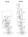
- FIG. 4A is an elevation view of the seat, when viewed along an arrow a of FIG. 3 and FIG. 4B is a sectional view of the seat taken along line b-b of FIG. 3.
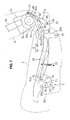
- FIG. 5 is an explanatory diagram, corresponding to FIG. 3, at a reclining state.
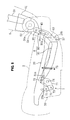
- FIG. 6 is an explanatory diagram, corresponding to FIG. 3, at a full-flat state.
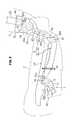
- FIG. 7 is an explanatory diagram, corresponding to FIG. 3, when a seat back is rotated or pivoted forward.
- FIG. 8 is an explanatory diagram, corresponding to FIG. 3, of another embodiment having a different shape of a slot provided at a link.
- FIG. 9 is an explanatory diagram, corresponding to FIG. 3 , of further another embodiment applied to a power seat.
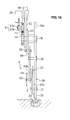
- FIG. 10 is a sectional view corresponding to FIG. 4B.
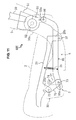
- FIG. 11 is an explanatory diagram, corresponding to FIG. 3, of further another embodiment having the linkage mechanism portion with a single link.
- FIG. 12 is an explanatory diagram corresponding to FIG. 5.
- FIG. 13 is an explanatory diagram corresponding to FIG. 6.
- FIG. 14 is an explanatory diagram corresponding to FIG. 7.
- FIG. 15 is an explanatory diagram, corresponding to FIG. 5, when the seat back is rotated or pivoted forward.
- FIG. 1 shows an embodiment in which a seat device according to a preferred embodiment of the present invention is applied to a reclining type of seat 1 that is disposed to the left of a rear portion of an automotive vehicle.
- a seat cushion 2 of the seat 1, on which a passenger is seated, is attached on a vehicle floor (directly or indirectly) via a base frame 3 (see FIG. 3).
- An ottoman 4 (a stand on which a foot or lower leg portion is placed or placeable) is provided to be at least partly storable or retractable at a front lower portion of the seat cushion 2.
- a seat back 5 is provided so as to extend substantially upward from a rear end portion of the seat cushion 2. At or close to an upper end of the seat back 5 is provided a headrest 6.
- FIG. 2 shows a frame structure of the seat cushion 2, omitting its cushion body.
- side frames 20, 20 that preferably are made of a steel-plate pressed material, for example.
- Their front and rear portions are coupled to each other via one or more coupling or pipe members 21, 22, respectively.
- At their intermediate portions are coupled to each other via one or more resilient members such as wire springs 23, 23.
- a plate member 25 as a frame of the ottoman 4 is rotatably or pivotably attached at the front pipe member 21 via arms 24, 24.
- One or more sub frames 30, 30 of the base frame 3 are respectively disposed substantially outside the cushion side frames 20, 20 so as to be at least partly located below and/or near the members 20, 20.
- the base sub frames 30, 30, which preferably are made of a pressed material, are coupled to each other via one or more connecting plates 31, 31 and/or at least one pipe member 32.
- To front and rear portions of the base side frames 30 are fixed one or more sliders 33, 33, which are shown only in FIG. 4.
- the sliders 33, 33 are guided by one or more slide rails 34, 34 (directly or indirectly) provided on or fixed to the vehicle floor so as to allow a movement substantially longitudinally in the vehicle.
- each base side frame 30 At or near a rear end of each base side frame 30 is provided an extending portion 30a to extend substantially upward in a bent or curved shape.
- Each lower end portion of a frame 50 of the seat back 5 (only its lower portion is illustrated in the figure) is rotatably or pivotably attached at the extending portion 30a via a knuckle 35 (rotational mechanism portion).
- the seat back frame 50 which preferably is made of at least one pipe member, for example, and formed substantially in a reverse-U shape, is disposed at or near an outside portion in the seat back 5.
- To both lower end portions of the frame 50 are connected (preferably welded) one or more brackets 51, 51, which preferably are made of a pressed material, and the brackets 51, 51 are coupled to each other via at least one pipe member 52.
- the pipe member 52 is a rotational (pivotal) axis of the seat back 5, and the knuckles 35, 35 are provided between the brackets 51, 51 and the base side frames 30, 30 preferably so as to be substantially coaxial to the pipe member 52.
- a reclining lever or knob 36 (not illustrated in FIGS. 3 and 4 )
- a lock member and a cam member in the knuckle 35 is or can be disengaged, not illustrated.
- the seat back 5 is enabled or assisted to rotate or pivot forward or rearward from its substantially upright position (hereinafter, referred to as a specified (predetermined or predeterminable) standard position SSP).
- a tilt mechanism portion 7 to tilt (move substantially vertically) the left-side side frame 20 and a linkage mechanism portion 8 to move the tilt mechanism portion 7 in accordance with a rotation or pivotal movement of the seat back 5, which are provided inside or corresponding to (on the right) the left-side side frame 20 of the seat cushion 2.
- the seat back 5 is rotated or pivoted from the specified (predetermined or predeterminable) standard position SSP shown in FIG. 3 (a position which is rotated rearward from a right vertical position by a certain angle of about 5 to about 20 degrees) to a reclining position (see FIG.
- the above-described specified angle may be set at an angle that can provide the passenger seated with a desirable reclining angle of the seat back 5 for tanking a nap, for example.
- the tilt mechanism portion 7 will be described.
- an extending portion 20a to extend at an angle different from 0° or 180°, preferably substantially substantially normal to the cushion side frame 20 or substantially downward.
- the extending portion 20a is connected to the front portion of the base side frame 30 via a link 70 and a rotating lever or knuckle 71 so as to be adjustable in its height.
- an extending portion 20b is provided at or near the rear end portion of the cushion side frame 20 to extend at an angle different from 0° or 180°, preferably substantially substantially normal to the cushion side frame 20 or substantially downward.
- the extending portion 20b is rotatably or pivotably supported around a support pin 37 attached to the base side frame 30.
- the cushion side frame 20 is or can be rotated or pivoted around the support pin 37 to support its rear end extending portion 20b, which enables the seat cushion 2 to rotate around a lateral axis (support pin 37 ) in such a manner that the front portion of the seat cushion 2 moves substantially vertically (tilt).
- a lateral axis support pin 37
- the amount of the longitudinal movement (longitudinal moving distance) of the front portion of the seat cushion 2 is smaller than the amount of its vertical movement (vertical moving distance).
- the front extending portion 20a of the cushion side frame 20 is connected to an upper end of the link 70 via a pin 72.
- a lower end of the link 70 is rotatably or pivotably connected to one end of the rotating lever 71 via a pin 73.
- the rotating lever 71 is a (preferably substantially L-shaped) angled or bent plate member as shown in FIG. 3, and to its bent portion is fixed a rotational or pivotal axis 74.
- the rotational axis 74 is provided so as to extend substantially laterally as shown in FIG. 2, and its both ends are rotatably or pivotably supported at the base side frames 30, 30.
- one end of the rotating lever 71 is configured to extend substantially forward from the rotational axis 74 and move substantially vertically, and the link 70 coupled to the lever 71 is located in front of the rotational axis 74, so that an acting point of a force that acts from the rotating lever 71 to the cushion side frame 20 is located substantially forward.
- This constitution means that the acting point of the force to the front portion of the seat cushion 2 is away from the rear axial supporting portion (support pin 37 ). Thereby, the front portion of the seat cushion 2 can be moved substantially vertically by a relatively small force.
- the one end of the rotating lever 71 (hereinafter, referred to as an output-side end, sometimes) that moves the cushion side frame 20 via the link 70 as described above is configured to substantially extend obliquely downward from the rotational axis 74 when the seat back 5 is in the specified standard position SSP shown in FIG. 3.
- the front portion of the cushion side frame 20 coupled to the output-side end of the lever 71 is located relatively below, where the seat face of the seat cushion 2 is positioned in a predetermined or predeterminable desirable slant state substantially corresponding (or with the aim of substantially corresponding) to the sitting position of the passenger.
- this state means that the seat cushion is in a standard position.
- a biasing member (such as a coil spring 75 ) is provided in back of the link 70 and the rotating lever 71 between the cushion side frame 20 and the base side frame 30 so as to extend substantially vertically.
- the front portion of the cushion side frame 20 is biased substantially downward by a tension of the spring 75.
- the biasing force of the spring 75 acts on the output-side end of the rotating lever 71 via the link 70 substantially downward, thereby pushing the rotating lever 71 counterclockwise in FIG. 3.
- a stopper portion is provided at an inside of the base side frame 30, which functions to prevent the cushion side frame 20 from moving substantially downward by engaging with the frame 20 when the seat cushion 2 is in the standard position.
- the front portion of the cushion side frame 20 does substantially not move further downward from its location that corresponds to the standard position of the seat cushion 2. Therefore, the standard position of the seat cushion 2 is the lowermost position of the front portion of the seat cushion 2.
- the other end of the rotating lever 71 which preferably is bent or curved or angled or formed in the substantially L shape, extends substantially upward from the rotational axis 74, and a front end of a second linkage link 81 of the linkage mechanism portion 8 is rotatably or pivotably connected to the other end of the rotating lever 71 via a pin 76 (hereinafter, the other end of the rotating lever 71 is referred to as an input-side end, sometimes).
- the other end of the rotating lever 71 is referred to as an input-side end, sometimes).
- FIG. 5 shows that the seat back 5 is rotated to its reclining position, where the front portion of the seat cushion 2 is in its uppermost position and the seat face is inclined rearward greatly. Thereby, the buttocks of the passenger seated can be held properly and prevented from sliding forward improperly on the seat face.
- this position of the seat cushion 2 will be referred to as a tilt position.
- the longitudinal movement of the link of the second linkage link 81 in accordance with the rotation of the seat back 5 can be efficiently changed to the vertical movement of the front portion of the seat cushion 2 by the L-shaped rotating lever 71, so the vertical moving distance (the amount of vertical movement) of the front portion of the seat cushion 2 can be made properly large with the compact structure.
- the input-side end of the rotating lever 71 is located above the rotational axis 74, and the input-side end of the rotating lever 71 is pulled rearward in accordance with the rearward rotation of the seat back 5, the input-side end of the rotating lever 71 moves rearward greatly away from the rotational axis 74. Accordingly, any interference between the both can be properly prevented and the desirably compact tilt mechanism portion 7 can be provided.
- the linkage mechanism portion 8 of the present embodiment comprises a first linkage link 80 and the second linkage link 81, which interconnect an arm member 53 fixed to the bracket 51 of the frame 50 of the seat back 5 and the rotating lever 71 of the tilt mechanism portion 7.
- One end (an end on a side of the seat back) of the first linkage link 80 is rotatably or pivotably coupled to the arm member 53 via a pin 82.
- the other end (an end on a side of the tilt mechanism portion) of the first linkage link 80 is rotatably or pivotably coupled to the rear end of the second linkage link 81 via a pin 83.
- the front end of the second linkage link 81 is rotatably or pivotably coupled to the input-side end of the rotating lever 71 of the tilt linkage mechanism portion 7 via the pin 76, as described above.
- a slot or elongated hole 80a is provided at the first linkage link 80 so as to extend substantially in a longitudinal direction of the link 80.
- the slot 80a engages with a support pin 38 that is fixed to the base side frame 30 so as to rotate or pivot and/or slide.
- the movement of the first linkage link 80 is restricted in such a manner that the engagement of the slot 80a and the support pin 38 is maintained while the one end (pin 82 ) of the first linkage link 80 rotates or pivots around the rotational support axis 52 in accordance with the rotation or pivotal movement of the seat back 5.
- a major movement pattern of the first linkage link 80 is changeable from either one of the rotation or pivotal movement around the support pin 38 and the slide guided by the support pin 38 to the other.
- the first linkage link 80 provides its major rotational movement around the support pin 38 because the moving direction (shown by an arrow a1 in FIG. 3 ) of the one end (pin 82 ) of the first linkage link 80 is greatly different from (or intersecting) the extending direction of the slot 80a (preferably the relative angle of intersection between the moving direction a1 of the one end (pin 82 ) of the first linkage link 80 and the extending direction of the slot 80a is in a range of between about 60° and about 120°, more preferably between about 70° and about 110°). Accordingly, the rear end of the second linkage link 81 coupled to the first linkage link 80 moves substantially longitudinally as shown by an arrow a2 in FIG. 3. Thus, the second linkage link 81 entirely moves longitudinally.
- the first linkage link 80 moves substantially vertically with the slide movement of the slot 80a guided by the support pin 38 because the moving direction of the one end (pin 82 ) of the first linkage link 80 is almost identical or close to the vertical direction in which the slot 8a extends (preferably in a range of about +20° to -20°). Then, when the seat back 5 rotates to its full-flat position shown in FIG. 6, the support pin 38 moves to the lowermost end of the slot 80a of the first linkage link 80.
- the first linkage link 80 provides its rotational major movement till the reclining position of the seat back 5. Accordingly, the tilt mechanism portion 7 is moved via the second linkage link 81 so as to change the inclination of the seat face of the seat cushion 2. Meanwhile, when the seat back 5 rotates further beyond the reclining position, the first linkage link 80 provides its vertically-slide major movement. Accordingly, the tilt mechanism portion 7 moves little and thereby the seat cushion 2 remains its tilt position.
- the reaction force of the tilt of the seat cushion 2 does not act on the seat back 5, so that the resistance force against the rotation of the seat back 5 may decrease quickly and thereby the passenger may have uncomfortable feelings in operation.
- the front portion of the seat cushion 2 is biased downward by the biasing member (the coil spring 75 ) and this downward biasing force is added as the above-described reaction force of the tilt, the above-described uncomfortable feelings may become improperly greater.
- At least one assist damper 9 (resistance-force adding device) is provided between the bracket 51 of the seat back frame 50 and the base side frame 30.
- the assist damper 9 applies the resistance force to the seat back 5 rotating or pivoting rearward beyond the reclining position.
- a well-known oil damper may be used as the assist damper 9, for example.
- a (preferably substantially rectangular) connecting portion 91 is provided at or near a lower end of a casing 90 of the damper 9 and it is rotatably or pivotably connected to a support pin 39 fixed to the base side frame 30.
- a rod 92 extending substantially upward from an upper end of the.casing 90 is provided a slot 92a as shown in the figure. The slot 92a engages with a support pin 54 fixed to the bracket 51 of the seat back frame 50 so as to rotate or pivot and/or slide.
- the damper 9 is layout in such a manner that the support pin 54 is positioned at the lowermost end of the slot 92a of the damper rod 92 when the seat back 5 is in the reclining position as shown in FIG. 5.
- the rod 92 does substantially not stroke despite the rotation of the seat back 5 from the specified standard position SSP to the reclining position, so a damping force is not generated by the assist damper 9.
- the seat back 5 rotates or pivots rearward beyond the reclining position
- the rod 92 is pushed into the casing 90, so the assist damper generates the damping force that becomes the resistance force against the rearward rotation of the seat back 5.
- the damping force is applied to the rotation or pivotal movement of the seat back 5 rotating rearward beyond the reclining position by the assist damper 9, even if the reaction force of the tilt of the seat cushion 2 does not act, the resistance force can be prevented from decreasing quickly after the rotation of the seat back 5 beyond the reclining position. Thus, the passenger does not have uncomfortable feelings.
- a slot or oblong hole 81a is provided at the front end portion of the second linkage link 81 coupled to the output-side end of the rotating lever 71.
- the connecting pin 76 engages with the slot 81a so as to rotate or pivot and/or slide.
- the slot 81a extends substantially longitudinally as shown in FIG. 3 and others, and the front end of the second linkage link 81 is connected to the input-side end of the rotating lever 71 so as to rotate or pivot and/or slide substantially longitudinally.
- the seat cushion 2 is in a state where its downward movement is prevented by the stopper portion via the cushion side frame 20. Accordingly, the rotating lever 71 is prevented from rotating or pivoting counterclockwise in FIG. 3 and others.
- the first linkage link 80 rotates or pivots and the second linkage link 81 moves longitudinally accordingly.
- such movements are not conveyed to the rotating lever 71, so that the seat cushion 2 substantially remains in its standard position.
- the seat cushion 2 is also located between its standard position and the tilt position. Accordingly, the tension force of the biasing member (coil spring 75 ) acting on the cushion side frame 20 acts on the rotating lever 71 via the link 70 so as to bias it counterclockwise in FIG. 3 and others.
- the pin 76 moves forward keeping its location at the front end of the slot 81a in accordance with the forward movement of the second linkage link 81. Accordingly, the rotating lever 71 rotates or pivots.
- the slot 81a at the connecting portion to the tilt mechanism portion 7 so that the conveyance of the rotational movement of the seat back 5 to the tilt mechanism portion 7 is restrained when the seat back 5 rotates or pivots forward from the specified standard position SSP.
- the conveyance of the rotational or pivotal movement of the seat back 5 to the tilt mechanism portion 7 may be restrained when the seat back 5 returns towards or to the specified standard position SSP from its rearward-rotated position, the front portion of the seat cushion 2 is biased downward by the tension force of the biasing member (the coil spring 75 ).
- the rotational or pivotal movement of the seat back 5 returning from the reclining position is conveyed to the tilt mechanism portion 7.
- FIGS. 3, 5-7 the movement of the seat 1 according to the present embodiment will be described referring to FIGS. 3, 5-7.
- the arm member 53 at the lower end of the seat back 5 rotates or pivots clockwise around the rotational support axis 52, and accordingly the first linkage link 80 rotates or pivots counterclockwise around the support pin 38 and the second linkage link 81 moves rearward, thereby pulling the input-side end of the rotating lever 71 rearward.
- the rotating lever 71 rotates or pivots clockwise in FIG. 3 and others and causes the front portion of the cushion side frame 20 via the link 70 to move substantially upward against the tension force of the coil spring 75.
- the rearward inclination of the seat face of the seat cushion 2 gradually increases, so that the buttocks of the passenger seated can be held properly.
- the seat back 5 is located in the reclining position shown in FIG. 5 to provide the desirable inclination of the seat back 5 e.g. for the passenger taking a nap, the seat cushion 2 is in the tilt position to provide a relatively large inclination, so that the buttocks of the passenger can be prevented from sliding forward improperly on the seat face.
- the rear end of the seat cushion 2 moves forward little (it moves rather rearward a little in this example), so the large gap is not generated between the rear end of the seat cushion 2 and the lower end of the seat back 5 taking its reclining position.
- part of the buttocks of the passenger can be properly prevented from being caught in this gap, thereby providing the proper sitting to the passenger.
- the first linkage link 80 moves substantially upward with the support pin 38 sliding in the slot 80a. Accordingly, the second linkage link 81 rotates or pivots counterclockwise (upward) around its front end (pin 76 ), without little longitudinal moving. Thus, until the seat back 5 moves to the full-flat position (FIG. 6 ), the rotating lever 71 does not rotate or pivot and the seat cushion 2 remains in the tilt position.
- the reaction force from the tilt mechanism portion 7 does not act on the seat back 5.
- the assist damper 9 since the assist damper 9 generates the damping force and thereby the resistance force is applied to the rearward rotation of the seat back 5, this resistance force can be prevented from decreasing quickly. Thus, the passenger may not have uncomfortable feelings.
- the second linkage link 81 When the seat back 5 returns towards or to the specified standard position SSP from the rearward position beyond the reclining position, until its returning to the reclining position, the second linkage link 81 only rotates or pivots around the front end (pin 76 ) and the rotating lever 71 does not rotate or pivot despite the rotation of the seat back 5 as described above. Meanwhile, while it returns towards or to the specified standard position SSP from the reclining position, the first linkage link 80 rotates or pivots clockwise around the support pin 38 in FIG. 3 and others. Thereby, the second linkage link 81 moves forward, and the rotating lever 71 is rotated or pivoted counterclockwise by the rotational biasing force of the coil spring 75.
- the seat back 5 gradually rises from the reclining position towards or to the specified standard position SSP, the front portion of the seat cushion 2 gradually lowers with the tension force of the coil spring 75 and the inclination of the seat face gradually becomes small.
- the seat face of the seat cushion 2 gets substantially its proper inclination state corresponding to the inclination of the seat back 5.
- the first linkage link 80 rotates or pivots around the support pin 38 and the second linkage link 81 moves forward.
- the rotating lever 71 does not rotate or pivot and the pin 76 at its input-side end slides rearward in the slot 81a of the second linkage link 81.
- the rotational movement of the seat back 5 is absorbed by the slot 81 a of the second linkage link 81 of the linkage mechanism portion 8 so as not to be conveyed to the tilt mechanism portion 7.
- the rotational movement of the seat back 5 is absorbed by the slot 81a of the second linkage link 81 so as not to be conveyed to the tilt mechanism portion 7.
- the seat cushion 2 can be tilted in accordance with the rotation or pivotal movement of the seat back 5 taking the reclining position so as to provide the proper inclination of the seat face.
- the gap generated between the seat cushion 2 and the seat back 5 is kept properly small, the conformability of the passenger seated can be improved.
- the conveyance of the rotational movement is restrained so as to keep the tilt position of the seat cushion 2. Thereby, it can be prevented that the inclination of the seat face becomes too large, thereby improving comfortable sitting and an operational performance of the seat with a simple and compact structure.
- the damping force is applied by the assist damper 9 considering the situation in which the reaction force does not act on the seat back 5 due to non-tilting movement occurring of the seat cushion 2 during the rearward rotation of the seat back 5, the resistance force against the rotation of the seat back 5 can be prevented from decreasing quickly during its reclining movement.
- the passenger may not have uncomfortable feelings.
- the seat cushion 2 can be kept substantially in its standard position and the inclination of the seat face can be prevented from becoming too small.
- a situation, so-called submarine phenomenon, in which the passenger would slip off the seat can be properly prevented.
- the above-described no (or little) change of the front portion of the seat cushion 2 in height despite the forward rotation of the seat back 5 from the specified standard position SSP means that there may be no need of any measures to avoid improper interference of the lower end of the ottoman stored with the vehicle floor, such as positioning the ottoman at a higher level, or forming a recess on the vehicle floor. This can provide a high flexibility in designing.
- a tilt mechanism portion 7 is connected to an front downward-extending portion 20a of a side frame 20 (cushion side fame) of a seat cushion 2 so as to move vertically the seat cushion 2.
- a rear substantially downward-extending portion 20b of the cushion side frame 20 is supported at a support pin 37 of a base side frame 30.
- the seat device according to the present invention is not limited to the above-described embodiment, but any other modification can be applied.
- the slot 80a of the first linkage link 80 engages with the support pin 38 on the side of the base side frame 30 in the seat 1 of the above-described embodiment. This is because the seat 1 is attached to the vehicle floor via the one or more sliders 33 and the slide rails 34 so as to move longitudinally.
- the support pin 38 may be attached to the vehicle floor, a pillar or the like as long as it is provided at a member that does not move (is fixed) regardless of the rotation of the seat back 5 or the tilt movement of the seat cushion 2.
- the assist damper 9 is provided to prevent the resistance force from decreasing quickly in the seat 1 of the above-described embodiment. This is because the seat 1 is a so-called manual type of seat in which the seat back 5 is manually operated for reclining. An assist spring, however, may be applied instead of the assist damper 9.
- the slot 80a of the first linkage link 80 may be configured to have a different width between its portion on a side of the seat back 5 and its portion on a side of the tilt mechanism portion 7, and a rubber ring 40 may be applied around the support pin 38 engaging with the slot 80a so that the resistance force of the support pin 38 receiving when sliding in the slot 80a can change during the reclining movement of the seat back 5.
- the width of the slot 80a on the side of the seat back 5 is wide and the resistance force of the support pin 38 sliding this portion is small. Meanwhile, the width of the slot 80a on the side of the tilt mechanism portion 7 is relatively narrow and the resistance force of the support pin 38 sliding this portion is relatively large with compression of the resilient ring or rubber ring 40.
- the border of the width change is set to correspond to the reclining position of the seat back 5, so the larger resistance force is applied to the rotational or pivotal movement of the seat back 5 when the seat back 5 rotates or pivots rearward from the specified standard position SSP beyond the reclining position.
- the different-width slot 80a and the resilient or rubber ring 40 form part of a resistance-force adding device in this embodiment.
- the present invention can be applied to a so-called power seat in which the seat back 5 is driven by a drive power e.g. of an electric motor or the like.
- a drive power e.g. of an electric motor or the like.
- a support axis portion 54 to rotatably or pivotably support the bracket 51, extending inward from the base side frame 30.
- a gear 41 is fixed to an inner end of the support axis portion, and a gear 42 engaging with the gear 41 is rotatably or pivotably attached to the bracket 51.
- a worm gear 43 (a worm 43a, a worm wheel 43b ) is attached or coupled to rotate together with the gear 42, which is driven by an electric motor 44.
- the worm 43a is rotated by the electric motor 44, and the worm wheel 43b is rotated by the worm 43a.
- the rotating gear 42 rotates or pivots around the fixed gear 41
- the seat back frame 50 rotates or pivots around the support axis portion 54
- the seat back 5 is rotated. Accordingly, since the seat back 5 is rotated or pivots towards or to the reclining position by the drive force of the electric motor 44, even if the resistance force against the rotation of the seat back 5 may decrease quickly, the passenger may not perceive that and thus may not have uncomfortable feelings.
- the electric motor 44 constitutes a drive device to rotate or pivot the seat back 5 via the rotational mechanism portion 8
- the motor 44 may be configured to rotate (drive) the seat back 5 only between the reclining position and the full-flat position of the seat back 5. Further, the rotation of the electric motor 44 may be prevented by engaging the gear 41, 42, for example, so a holding member (not illustrated) to hold the rotational position of the seat back 5 may be provided.
- the tilt mechanism portion 7 and the linkage mechanism portion 8 of the above-described embodiment is just one example and should not be limited to this.
- the linkage mechanism portion 8 may be comprised of one (single) link 85 as shown in FIGS. 11-15, for example.
- the seat 1 shown in these figures has a similar or substantially the same structure as that of the above-described embodiment, except following structures of the tilt mechanism portion 7, the linkage mechanism portion 8 and the arm member 55. Accordingly, the similar or same members are denoted by the same reference characters, and descriptions of those will be omitted here.
- a rotating or pivoting lever 77 of the tilt mechanism portion 7 of the present embodiment in FIG. 11 is provided.
- the rotational or pivotal axis 74 is fixed to one end (upper end in the figure) of the lever 77, and the other end (lower end in the figure) of the lever 77 is comprised of a link that constitutes both its input side and its output side.
- the link 70 coupled to the rotating lever 77 via the pin 73 has a longer length than the one of the above-described embodiment.
- the front end portion of the above-described linkage link 85 is coupled to the pin 73 connecting the both via a slot 85a so as to rotate or pivot and/or slide.
- the linkage link 85 preferably is a long link angled or bent or curved or substantially formed in a L shape, which appears to unify (or correspond to) the first and second linkage links 80, 81 of the previous embodiment, and its rear bent portion extends upward beside the upward-extending portion 30a of the base side frame 30 and the arm member 55 of the seat back 5 is rotatably or pivotably connected to its upper end of the upward-extending rear bent portion via a pin 86.
- the arm member 55 which rotates or pivots along with the seat back 5 to convey its rotational or pivotal movement to the linkage mechanism portion 8, like the one (arm member 53 ) of the previous embodiment but has a different shape and position from that, has a slot 55a as shown in the figure.
- the above-described pin 86 attached to the rear end of the linkage link 85 engages with this slot 55a so as to rotate or pivot and/or slide.
- the seat back 5 rotates or pivots rearward further beyond the reclining position (FIG. 12 ), the pin 86 at the rear end of the linkage link 85 slides in the slot 55a of the arm member 55.
- the linkage link 85 just rotates or pivots around its front end (pin 73) despite the rotation of the arm member 55 around the support axis 52 in accordance with the rotation or pivotal movement of the seat back 5, and it does not cause movements of the rotating lever 77 and the link 70.
- the seat cushion 2 is kept substantially in the tilt position until the seat back 5 moves its full-flat position shown in FIG. 13.
- the rear end of the linkage link 85 is further pulled substantially upward and rearward by the pin 86.
- the pin 73 is located at the front end of the slot 85a, so the pin 73 is also pulled substantially obliquely upward and rearward in accordance with the movement of the linkage link 85.
- the rotating lever 77 rotates or pivots counterclockwise around the rotating axis 74 in the figure.
- the front portion of the cushion side frame 20 is pulled upward via the link 70, so the seat face of the seat cushion 2 lowers as shown in FIG. 15.
- the seat back 5 can be rotated or pivoted forward greatly without interference with the seat cushion 2 in such a manner that its back face is in the substantially horizontal position.
- the seat cushion 2 is allowed to rotate or pivot just by approximately 15 degrees of angle (specified second angle) while the seat back 5 rotates or pivots forward from the specified standard position SSP (FIG. 11 ) to the forward-rotated position (FIG. 15 ) by more than 90 degrees (specified first angle).
- the downward tilt angle of the seat cushion 2 is relatively small, there is no need of the seat cushion 2 being provided far away from the vehicle floor.
- a high flexibility in designing of the seat cushion 2 can be provided.
- the linkage link 85 preferably is bent or curved or angled or formed substantially in the L shape, the linkage link 85 may not extend improperly upward even when the seat back 5 rotates rearward greatly. Thus, interference of the seat cushion 2 with the cushion body or the like can be easily avoided.
Landscapes
- Engineering & Computer Science (AREA)
- Aviation & Aerospace Engineering (AREA)
- Transportation (AREA)
- Mechanical Engineering (AREA)
- Seats For Vehicles (AREA)
- Chairs For Special Purposes, Such As Reclining Chairs (AREA)
Applications Claiming Priority (3)
| Application Number | Priority Date | Filing Date | Title |
|---|---|---|---|
| JP2006255654A JP2008073213A (ja) | 2006-09-21 | 2006-09-21 | シート装置 |
| JP2006255656A JP2008073214A (ja) | 2006-09-21 | 2006-09-21 | シート装置 |
| JP2006255660A JP4923905B2 (ja) | 2006-09-21 | 2006-09-21 | シート装置 |
Publications (2)
| Publication Number | Publication Date |
|---|---|
| EP1902896A2 true EP1902896A2 (de) | 2008-03-26 |
| EP1902896A3 EP1902896A3 (de) | 2010-12-08 |
Family
ID=38904776
Family Applications (1)
| Application Number | Title | Priority Date | Filing Date |
|---|---|---|---|
| EP07018381A Withdrawn EP1902896A3 (de) | 2006-09-21 | 2007-09-19 | Sitzvorrichtung |
Country Status (2)
| Country | Link |
|---|---|
| US (1) | US7703851B2 (de) |
| EP (1) | EP1902896A3 (de) |
Cited By (5)
| Publication number | Priority date | Publication date | Assignee | Title |
|---|---|---|---|---|
| WO2012146898A1 (en) * | 2011-04-26 | 2012-11-01 | Corcost Limited | A motorised cam arrangement |
| US9656578B2 (en) | 2014-05-23 | 2017-05-23 | Toyota Boshoku Kabushiki Kaisha | Vehicle seat |
| US9663005B2 (en) | 2014-05-23 | 2017-05-30 | Toyota Boshoku Kabushiki Kaisha | Vehicle seat |
| US9987953B2 (en) | 2014-05-23 | 2018-06-05 | Toyota Boshoku Kabushiki Kaisha | Vehicle seat |
| CN111409519A (zh) * | 2020-04-13 | 2020-07-14 | 安徽江淮汽车集团股份有限公司 | 防下潜结构、座椅及车辆 |
Families Citing this family (32)
| Publication number | Priority date | Publication date | Assignee | Title |
|---|---|---|---|---|
| GB0708053D0 (en) | 2007-04-26 | 2007-06-06 | Leuven | Adjustable furniture |
| DE112008003251B4 (de) * | 2007-12-03 | 2017-07-27 | Toyota Boshoku K.K. | Fahrzeugsitz |
| JP5119910B2 (ja) * | 2007-12-26 | 2013-01-16 | トヨタ紡織株式会社 | 車両用シート |
| GB0918685D0 (en) | 2009-10-23 | 2009-12-09 | Integrated Furniture Technolog | Adjustable furniture |
| US9241571B2 (en) * | 2009-08-18 | 2016-01-26 | Integrated Furniture Technologies Limited | Adjustable furniture |
| KR101394083B1 (ko) * | 2010-06-24 | 2014-05-13 | 존슨 컨트롤스 테크놀러지 컴퍼니 | 전자기계식 푸시 버튼 차량 시트 작동 기구 |
| CN103052532B (zh) * | 2010-08-04 | 2016-01-20 | 约翰逊控股公司 | 用于车座的固定装置和车座 |
| US8388065B2 (en) * | 2010-09-07 | 2013-03-05 | Honda Motor Co., Ltd. | Vehicle seat |
| US10004334B2 (en) | 2010-09-09 | 2018-06-26 | Integrated Furniture Technologies Limited | Lift-recliner chair |
| GB201015084D0 (en) | 2010-09-09 | 2010-10-27 | Integrated Furniture Technologies Ltd | Lift-recliner chair |
| JP5218506B2 (ja) * | 2010-09-17 | 2013-06-26 | アイシン精機株式会社 | シートリフター装置 |
| BR122015025310B1 (pt) | 2011-10-04 | 2021-01-12 | Formway Furniture Limited | cadeira |
| CN103847538B (zh) * | 2012-11-30 | 2017-11-10 | 提爱思科技股份有限公司 | 交通工具用座椅 |
| JP6040817B2 (ja) * | 2013-03-21 | 2016-12-07 | トヨタ紡織株式会社 | 乗物用シート |
| US9061606B2 (en) * | 2013-04-03 | 2015-06-23 | AISIN Technical Center of America, Inc. | Electric release manual seat |
| GB2518394A (en) | 2013-09-20 | 2015-03-25 | Sherborne Upholstery Ltd | Adjustable bed |
| US10214120B2 (en) * | 2014-03-25 | 2019-02-26 | Cvg Management Corporation | Seat tilt control mechanism |
| CN107205551B (zh) | 2014-12-11 | 2020-09-25 | 德沃特奥金有限公司 | 可调节家具 |
| US12575682B2 (en) | 2015-03-11 | 2026-03-17 | Motus Mechanics Ltd. | Adjustable furniture |
| GB201610212D0 (en) | 2016-06-13 | 2016-07-27 | Motus Mech Ltd | Adjustable bed |
| GB201504140D0 (en) | 2015-03-11 | 2015-04-22 | Motus Mechanics Ltd | Adjustable bed |
| CN107444201A (zh) * | 2017-08-02 | 2017-12-08 | 延锋安道拓座椅有限公司 | 一种座椅机构 |
| US10343558B2 (en) | 2017-10-19 | 2019-07-09 | Nio Usa, Inc. | Fixed structure seat |
| CN107901795B (zh) * | 2017-12-20 | 2024-05-17 | 车质尚(北京)汽车制造有限公司 | 一种多功能座椅骨架结构 |
| GB201813009D0 (en) | 2018-08-09 | 2018-09-26 | Eevolv Ltd | A drive mechanism |
| EP3977904B1 (de) | 2019-03-11 | 2022-10-12 | Storyteller Overland, LLC | Rv-nachrüstsystem |
| KR20220014463A (ko) * | 2020-07-28 | 2022-02-07 | 현대자동차주식회사 | 시트용 리클라이닝 장치 |
| US11198378B1 (en) * | 2021-06-24 | 2021-12-14 | Ming C Kuo | Double-deck passenger vehicle |
| JP7632204B2 (ja) * | 2021-09-21 | 2025-02-19 | トヨタ紡織株式会社 | 乗物用シート |
| KR20240033822A (ko) * | 2022-09-06 | 2024-03-13 | 현대자동차주식회사 | 폴드 앤 다이브 시트의 시트쿠션 익스텐션 장치 |
| KR102784551B1 (ko) * | 2022-12-13 | 2025-03-21 | 현대트랜시스 주식회사 | 자동차용 시트백 각도 조절장치 |
| US12428159B1 (en) * | 2025-04-08 | 2025-09-30 | Ming C Kuo | Double-deck passenger vehicle |
Citations (4)
| Publication number | Priority date | Publication date | Assignee | Title |
|---|---|---|---|---|
| US2926948A (en) | 1957-10-16 | 1960-03-01 | Gen Motors Corp | Folding seat structure for a vehicle body |
| FR2569628A1 (fr) | 1984-08-28 | 1986-03-07 | Tachikawa Spring Co | Siege de vehicule |
| JPS62192114A (ja) | 1986-02-17 | 1987-08-22 | 日産自動車株式会社 | 車両用座席 |
| JPH06245837A (ja) | 1993-02-24 | 1994-09-06 | Ikeda Bussan Co Ltd | 車両用シート |
Family Cites Families (4)
| Publication number | Priority date | Publication date | Assignee | Title |
|---|---|---|---|---|
| IT206947Z2 (it) * | 1986-06-12 | 1987-10-26 | Pro Cord Srl | Sedia con schienale articolato |
| DE19645772A1 (de) * | 1996-11-07 | 1998-05-14 | Hammerstein Gmbh C Rob | Kraftfahrzeug mit einem Sitzträger mit Sitztiefenverstellung |
| DE60200399T2 (de) * | 2002-07-24 | 2005-05-04 | Ciar S.P.A., Borgo Santa Maria | Sitzmöbel mit einem Sitz und einer Rückenlehne |
| DE602004023681D1 (de) * | 2003-11-20 | 2009-12-03 | Toyota Boshoku Kk | Klappsitz |
-
2007
- 2007-08-28 US US11/892,829 patent/US7703851B2/en not_active Expired - Fee Related
- 2007-09-19 EP EP07018381A patent/EP1902896A3/de not_active Withdrawn
Patent Citations (4)
| Publication number | Priority date | Publication date | Assignee | Title |
|---|---|---|---|---|
| US2926948A (en) | 1957-10-16 | 1960-03-01 | Gen Motors Corp | Folding seat structure for a vehicle body |
| FR2569628A1 (fr) | 1984-08-28 | 1986-03-07 | Tachikawa Spring Co | Siege de vehicule |
| JPS62192114A (ja) | 1986-02-17 | 1987-08-22 | 日産自動車株式会社 | 車両用座席 |
| JPH06245837A (ja) | 1993-02-24 | 1994-09-06 | Ikeda Bussan Co Ltd | 車両用シート |
Cited By (10)
| Publication number | Priority date | Publication date | Assignee | Title |
|---|---|---|---|---|
| WO2012146898A1 (en) * | 2011-04-26 | 2012-11-01 | Corcost Limited | A motorised cam arrangement |
| US9656578B2 (en) | 2014-05-23 | 2017-05-23 | Toyota Boshoku Kabushiki Kaisha | Vehicle seat |
| US9663005B2 (en) | 2014-05-23 | 2017-05-30 | Toyota Boshoku Kabushiki Kaisha | Vehicle seat |
| US9987953B2 (en) | 2014-05-23 | 2018-06-05 | Toyota Boshoku Kabushiki Kaisha | Vehicle seat |
| DE102015209436B4 (de) | 2014-05-23 | 2019-07-18 | Toyota Boshoku Kabushiki Kaisha | Fahrzeugsitz |
| DE102015209437B4 (de) | 2014-05-23 | 2019-07-18 | Toyota Boshoku Kabushiki Kaisha | Fahrzeugsitz |
| DE102015209438B4 (de) * | 2014-05-23 | 2019-07-18 | Toyota Boshoku Kabushiki Kaisha | Fahrzeugsitz |
| DE102015209437C5 (de) | 2014-05-23 | 2022-09-08 | Toyota Boshoku Kabushiki Kaisha | Fahrzeugsitz |
| CN111409519A (zh) * | 2020-04-13 | 2020-07-14 | 安徽江淮汽车集团股份有限公司 | 防下潜结构、座椅及车辆 |
| CN111409519B (zh) * | 2020-04-13 | 2021-11-16 | 安徽江淮汽车集团股份有限公司 | 防下潜结构、座椅及车辆 |
Also Published As
| Publication number | Publication date |
|---|---|
| US7703851B2 (en) | 2010-04-27 |
| EP1902896A3 (de) | 2010-12-08 |
| US20080073960A1 (en) | 2008-03-27 |
Similar Documents
| Publication | Publication Date | Title |
|---|---|---|
| EP1902896A2 (de) | Sitzvorrichtung | |
| EP1924463B1 (de) | Sitzanordnung mit einem sitzpolsterschwenkmechanismus | |
| US8047610B2 (en) | Vehicle seats | |
| US6986542B2 (en) | Retractable seats | |
| EP1729997B1 (de) | Im boden verstaubare sitzanordnung mit einziehbarer vorderbeingestängeanordnung | |
| EP1531079A2 (de) | Sitzschienenvorrichtung | |
| CN112550096B (zh) | 车辆用后座椅 | |
| KR20080083132A (ko) | 절첩식 평탄 시트 조립체 | |
| JP2002512916A (ja) | 単一位置記憶装置を備える直線リクライニング装置 | |
| KR101884741B1 (ko) | 래치회동형 리어시트 슬라이딩 장치 | |
| CN108602454A (zh) | 汽车用座椅 | |
| US9352670B2 (en) | Fold and kneel seat with rearward folding motion | |
| JPH11244082A (ja) | 車両用シート | |
| US6974174B2 (en) | Retractable seats | |
| CN114475377A (zh) | 车辆座椅 | |
| JP2009227208A (ja) | リフタ機構付き乗物用シート | |
| KR101372108B1 (ko) | 시트 높이 조절 연동형 슬라이딩 레버장치 | |
| JP4534831B2 (ja) | 自動車のシート位置調整装置 | |
| JP4059811B2 (ja) | 車両用シート装置 | |
| EP0027307A1 (de) | Fahrzeugsitze | |
| KR102836913B1 (ko) | 자동차용 시트쿠션 익스텐션 및 레그레스트 장치 | |
| JP7423698B2 (ja) | 車両用シートフレーム及び車両用シート | |
| JP2021062843A (ja) | ヘッドレスト格納装置 | |
| JP4730247B2 (ja) | 車両用シート | |
| JP2008017905A (ja) | 車両用シート装置 |
Legal Events
| Date | Code | Title | Description |
|---|---|---|---|
| PUAI | Public reference made under article 153(3) epc to a published international application that has entered the european phase |
Free format text: ORIGINAL CODE: 0009012 |
|
| AK | Designated contracting states |
Kind code of ref document: A2 Designated state(s): AT BE BG CH CY CZ DE DK EE ES FI FR GB GR HU IE IS IT LI LT LU LV MC MT NL PL PT RO SE SI SK TR |
|
| AX | Request for extension of the european patent |
Extension state: AL BA HR MK YU |
|
| PUAL | Search report despatched |
Free format text: ORIGINAL CODE: 0009013 |
|
| AK | Designated contracting states |
Kind code of ref document: A3 Designated state(s): AT BE BG CH CY CZ DE DK EE ES FI FR GB GR HU IE IS IT LI LT LU LV MC MT NL PL PT RO SE SI SK TR |
|
| AX | Request for extension of the european patent |
Extension state: AL BA HR MK RS |
|
| RIC1 | Information provided on ipc code assigned before grant |
Ipc: B60N 2/18 20060101ALI20101029BHEP Ipc: B60N 2/30 20060101ALI20101029BHEP Ipc: B60N 2/22 20060101AFI20080116BHEP |
|
| 17P | Request for examination filed |
Effective date: 20110608 |
|
| AKX | Designation fees paid |
Designated state(s): DE |
|
| RIC1 | Information provided on ipc code assigned before grant |
Ipc: B60N 2/18 20060101ALI20110831BHEP Ipc: B60N 2/30 20060101ALI20110831BHEP Ipc: B60N 2/22 20060101AFI20110831BHEP |
|
| GRAP | Despatch of communication of intention to grant a patent |
Free format text: ORIGINAL CODE: EPIDOSNIGR1 |
|
| STAA | Information on the status of an ep patent application or granted ep patent |
Free format text: STATUS: THE APPLICATION IS DEEMED TO BE WITHDRAWN |
|
| 18D | Application deemed to be withdrawn |
Effective date: 20120313 |