EP1902943A1 - Aussenbordmotor - Google Patents
Aussenbordmotor Download PDFInfo
- Publication number
- EP1902943A1 EP1902943A1 EP06768037A EP06768037A EP1902943A1 EP 1902943 A1 EP1902943 A1 EP 1902943A1 EP 06768037 A EP06768037 A EP 06768037A EP 06768037 A EP06768037 A EP 06768037A EP 1902943 A1 EP1902943 A1 EP 1902943A1
- Authority
- EP
- European Patent Office
- Prior art keywords
- transmission ratio
- ratio changing
- propeller
- shifting
- clutch
- Prior art date
- Legal status (The legal status is an assumption and is not a legal conclusion. Google has not performed a legal analysis and makes no representation as to the accuracy of the status listed.)
- Granted
Links
Images





Classifications
-
- B—PERFORMING OPERATIONS; TRANSPORTING
- B63—SHIPS OR OTHER WATERBORNE VESSELS; RELATED EQUIPMENT
- B63H—MARINE PROPULSION OR STEERING
- B63H5/00—Arrangements on vessels of propulsion elements directly acting on water
- B63H5/07—Arrangements on vessels of propulsion elements directly acting on water of propellers
- B63H5/08—Arrangements on vessels of propulsion elements directly acting on water of propellers of more than one propeller
- B63H5/10—Arrangements on vessels of propulsion elements directly acting on water of propellers of more than one propeller of coaxial type, e.g. of counter-rotative type
-
- B—PERFORMING OPERATIONS; TRANSPORTING
- B63—SHIPS OR OTHER WATERBORNE VESSELS; RELATED EQUIPMENT
- B63H—MARINE PROPULSION OR STEERING
- B63H20/00—Outboard propulsion units, e.g. outboard motors or Z-drives; Arrangements thereof on vessels
- B63H20/14—Transmission between propulsion power unit and propulsion element
-
- B—PERFORMING OPERATIONS; TRANSPORTING
- B63—SHIPS OR OTHER WATERBORNE VESSELS; RELATED EQUIPMENT
- B63H—MARINE PROPULSION OR STEERING
- B63H20/00—Outboard propulsion units, e.g. outboard motors or Z-drives; Arrangements thereof on vessels
- B63H20/14—Transmission between propulsion power unit and propulsion element
- B63H20/20—Transmission between propulsion power unit and propulsion element with provision for reverse drive
-
- B—PERFORMING OPERATIONS; TRANSPORTING
- B63—SHIPS OR OTHER WATERBORNE VESSELS; RELATED EQUIPMENT
- B63H—MARINE PROPULSION OR STEERING
- B63H23/00—Transmitting power from propulsion power plant to propulsive elements
- B63H23/30—Transmitting power from propulsion power plant to propulsive elements characterised by use of clutches
-
- B—PERFORMING OPERATIONS; TRANSPORTING
- B63—SHIPS OR OTHER WATERBORNE VESSELS; RELATED EQUIPMENT
- B63H—MARINE PROPULSION OR STEERING
- B63H20/00—Outboard propulsion units, e.g. outboard motors or Z-drives; Arrangements thereof on vessels
- B63H2020/005—Arrangements of two or more propellers, or the like on single outboard propulsion units
- B63H2020/006—Arrangements of two or more propellers, or the like on single outboard propulsion units of coaxial type, e.g. of counter-rotative type
-
- B—PERFORMING OPERATIONS; TRANSPORTING
- B63—SHIPS OR OTHER WATERBORNE VESSELS; RELATED EQUIPMENT
- B63H—MARINE PROPULSION OR STEERING
- B63H23/00—Transmitting power from propulsion power plant to propulsive elements
- B63H23/02—Transmitting power from propulsion power plant to propulsive elements with mechanical gearing
- B63H2023/0258—Transmitting power from propulsion power plant to propulsive elements with mechanical gearing comprising gearings with variable gear ratio, other than reversing drives or trolling drives
-
- B—PERFORMING OPERATIONS; TRANSPORTING
- B63—SHIPS OR OTHER WATERBORNE VESSELS; RELATED EQUIPMENT
- B63H—MARINE PROPULSION OR STEERING
- B63H23/00—Transmitting power from propulsion power plant to propulsive elements
- B63H23/02—Transmitting power from propulsion power plant to propulsive elements with mechanical gearing
- B63H2023/0283—Transmitting power from propulsion power plant to propulsive elements with mechanical gearing using gears having orbital motion
-
- B—PERFORMING OPERATIONS; TRANSPORTING
- B63—SHIPS OR OTHER WATERBORNE VESSELS; RELATED EQUIPMENT
- B63H—MARINE PROPULSION OR STEERING
- B63H23/00—Transmitting power from propulsion power plant to propulsive elements
- B63H23/30—Transmitting power from propulsion power plant to propulsive elements characterised by use of clutches
- B63H2023/305—Transmitting power from propulsion power plant to propulsive elements characterised by use of clutches using fluid or semifluid as power transmitting means
-
- F—MECHANICAL ENGINEERING; LIGHTING; HEATING; WEAPONS; BLASTING
- F16—ENGINEERING ELEMENTS AND UNITS; GENERAL MEASURES FOR PRODUCING AND MAINTAINING EFFECTIVE FUNCTIONING OF MACHINES OR INSTALLATIONS; THERMAL INSULATION IN GENERAL
- F16H—GEARING
- F16H3/00—Toothed gearings for conveying rotary motion with variable gear ratio or for reversing rotary motion
- F16H3/44—Toothed gearings for conveying rotary motion with variable gear ratio or for reversing rotary motion using gears having orbital motion
- F16H3/62—Gearings having three or more central gears
- F16H3/64—Gearings having three or more central gears composed of a number of gear trains, the drive always passing through all the trains, each train having not more than one connection for driving another train
Definitions
- the present invention relates to an outboard motor having a power transmission mechanism for transmitting engine power to a propeller and, more particularly, to an outboard motor having a power transmission mechanism provided with a transmission ratio changing unit for changing the output from an engine and transmitting it to a propeller.
- Patent Document 1 discloses an outboard motor having a first drive shaft connected to the output shaft of the engine, a second drive shaft disposed coaxially with the first drive shaft via a transmission ratio changing unit, and a speed reducing and reversing mechanism for transmitting torque transmitted to the second drive shaft to a propeller shaft.
- the transmission ratio changing unit comprises first and second planetary gear trains each including a sun gear, a plurality of planetary gears, and an internal gear with which the planetary gears are in meshing engagement.
- the axes of rotation of the sun gears of the first and second planetary gear trains are connected by a rotating spindle to integrate them, and a brake mechanism which is operable from outside is disposed adjacent to the rotating spindle.
- the first drive shaft transmits its torque to the internal gear of the first planetary gear train, and the rotation of an arm for the planetary gears of the first planetary gear train, which is rotated by the torque, is transmitted to the second drive shaft.
- the arm for the planetary gears of the first planetary gear train and the internal gear of the second planetary gear train are integrated with each other, and a one-way clutch which allows an arm for the planetary gears of the second planetary gear train to rotate in a predetermined direction is provided.
- Some outboard motors mounted on boats have a first propeller and a second propeller arranged in tandem in opposed relationship and a contra-rotating propeller mechanism for rotating the first propeller and the second propeller in directions opposite to each other as disclosed in, for example, Patent Document 2 and Patent Document 3.
- exhaust gas is discharged into water in both Patent Document 2 and Patent Document 3
- exhaust gas is discharged from inside of a propeller cylinder in Patent Document 2 and from outside of a propeller cylinder in Patent Document 3 during acceleration.
- a contra-rotating propeller system has very excellent propeller cavitation performance since it has two propellers for producing thrust and thus the total area of the propeller vanes is greater than that of a single propeller system having one propeller for producing thrust. Because of this feature, free spinning of the propellers seldom occurs during acceleration or deceleration of the boat. Therefore, the outboard motor is excellent in starting and acceleration performance and braking and deceleration performance.
- a contra-rotating propeller engine is that the required torque, especially on the low-speed side, is very large as compared to a single propeller engine having one propeller for producing thrust all the more because free spinning of the propellers seldom occurs. Therefore, a means for increasing the engine output such as a turbo charger or super charger must be added. However, since there is a limit to the amount by which the torque can be increased and since there is naturally a response time lag between an operation to increase the output and an actual increase in the engine output, the feature of a contra-rotating propeller system cannot be fully exploited. In addition, such a means tends to lower the traveling mileage.
- Patent Document 3 a structure in which exhaust gas discharged from a propeller boss part can swirls around the propeller vanes is employed in order to reduce the required torque caused by free spinning of the propellers. This method, however, produces a result in which the high water catching ability of the contra-rotating propeller system is not fully exploited.
- a propeller with a relatively large diameter and a high pitch slowly is preferred in terms of the propeller efficiency and results in improvement of the maximum speed and traveling mileage.
- a propeller with a higher pitch requires larger propeller driving torque at the time of acceleration, and great improvement of the traveling performance by increasing the propeller pitch cannot be expected when a low-speed torque improving means such as a turbo charger as mentioned before is employed.
- the present invention has been made in view of the above problems and it is, therefore, an object of the present invention to provide an outboard motor which has a small-sized transmission ratio changing unit and is simple in structure.
- Another object of the present invention is, in view of the above problems, to provide an outboard motor which can take the best advantages of the thrust characteristics of a contra-rotating propeller system, in which free spinning of propellers seldom occurs, and can achieve propeller torque characteristics to cope with an increase in propeller pitch.
- the present invention is constituted as follows.
- the invention described in Claim 1 is an outboard motor having a power transmission mechanism for transmitting power of an engine to a propeller, the power transmission mechanism having a transmission ratio changing unit for changing the output from the engine and transmitting the output to the propeller;
- the transmission ratio changing unit having a transmission ratio changing planetary gear train including a transmission ratio changing sun gear, transmission ratio changing planetary gears, and a transmission ratio changing internal gear, the transmission ratio changing internal gear being connected to an input side shaft on the engine side, and the transmission ratio changing planetary gears being connected to an output side shaft on the propeller side;
- the transmission ratio changing sun gear being connected to a stationary portion via a one-way clutch, and the transmission ratio changing planetary gears and the transmission ratio changing internal gear and/or the transmission ratio changing sun gear being connected by an on-off clutch, in which when the on-off clutch is disengaged, the one-way clutch is engaged and the speed from the input side shaft is outputted from the output side shaft with a reduced speed, and when the on-off clutch is engaged, the one-
- the invention described in Claim 2 has a configuration, in addition to the configuration described in Claim 1, in which the transmission ratio changing unit has a shifting planetary gear train disposed below the transmission ratio changing planetary gear train and including a set of shifting sun gear, shifting double planetary gears, and a shifting internal gear, the shifting double planetary gears being connected to the transmission ratio changing planetary gears, and the shifting sun gear being connected to the output side shaft on the propeller side; and the shifting internal gear being connected to a stationary portion via a reverse clutch, and the shifting double planetary gears and the shifting internal gear and/or the shifting sun gear being connected by a forward clutch, in which: when the forward clutch is engaged with the reverse clutch disengaged, the shifting sun gear, the shifting double planetary gears and the shifting internal gear rotate together to cause the transmission ratio changing planetary gears of the transmission ratio changing planetary gear train and the shifting sun gear of the shifting planetary gear train to rotate in the same direction at the same speed to establish a forward state; when the forward clutch and the reverse clutch are disengaged, each of
- the invention described in Claim 3 has a configuration, in addition to the configuration described in Claim 2, in which it further includes a cylindrical water pump driving shaft rotatably disposed around the output side shaft and connected to the shifting double planetary gears, and a water pump mounted on the water pump driving shaft.
- the invention described in Claim 4 has a configuration, in addition to the configuration described in Claim 1 or 2, in which it further includes an oil pump, mounted on the input side shaft, which is activated by rotation of the input side shaft, and a control valve for controlling the supply of oil from the oil pump to each of the clutches.
- the invention described in Claim 5 has a configuration, in addition to the configuration described in Claim 1 or 2, in which each of the clutches is a multiple-disc clutch.
- the invention described in Claim 6 has a configuration, in addition to the configuration described in Claim 1 or 2, in which it further includes a power transmission mechanism for transmitting the power of the engine to a first propeller and a second propeller; and contra-rotating propeller mechanism for rotating the first propeller and the second propeller in directions opposite to each other; and in which the transmission ratio changing unit for changing the transmission ratio between the input side and the output side thereof is provided in the power transmission mechanism.
- the invention described in Claim 7 has a configuration, in addition to the configuration described in Claim 6, in which the contra-rotating propeller mechanism has two driven gears for driving the first propeller and the second propeller, respectively, and a pinion gear for driving the two driven gears simultaneously; and in which the output side of the transmission ratio changing unit is coupled to the pinion gear.
- the invention described in Claim 8 has a configuration, in addition to the configuration described in Claim 1 or 2, in which it further includes a torque converter device disposed between the output side of the engine and the input side of the transmission ratio changing unit.
- the present invention provides the following effects.
- the present invention is constituted as follows.
- the transmission ratio changing unit of the power transmission mechanism has a transmission ratio changing planetary gear train including a transmission ratio changing sun gear, transmission ratio changing planetary gears, and a transmission ratio changing internal gear.
- the transmission ratio changing internal gear is connected to an input side shaft on the engine side.
- the transmission ratio changing planetary gears are connected to an output side shaft on the propeller side.
- the transmission ratio changing sun gear is connected to a stationary portion via a one-way clutch.
- the transmission ratio changing planetary gears and the transmission ratio changing internal gear and/or the transmission ratio changing sun gear are connected by an on-off clutch.
- the on-off clutch When the on-off clutch is disengaged, the one-way clutch is engaged and the speed from the input side shaft is outputted from the output side shaft with a reduced speed.
- the on-off clutch is engaged, the one-way clutch is disengaged and the speed from the input side shaft is outputted from the output side shaft with the same speed. Therefore, there can be provided a small-sized, transmission ratio changing unit with a simple
- the transmission ratio changing unit has a transmission ratio changing planetary gear train including the transmission ratio changing sun gear, the transmission ratio changing planetary gears, and the transmission ratio changing internal gear, the transmission ratio can be changed without shutting off power or changing the engagement of gears during the changing operation. Since the power for driving the propellers is not interrupted, a transmission ratio changing operation can be carried out easily even during acceleration and optimum transmission ratio change timing can be realized in boats, which receives a much larger resistance than land transportation vehicles during traveling.
- the transmission ratio changing unit has a shifting planetary gear train disposed below the transmission ratio changing planetary gear train and including a shifting sun gear, shifting double planetary gears, and a shifting internal gear so that shift switching can be carried out. Therefore, a transmission ratio changing mechanism and a shifting device can be assembled in a more compact manner.
- a cylindrical water pump driving shaft is rotatably disposed around the output side shaft and connected to the shifting double planetary gears, and a water pump is mounted on the water pump driving shaft. Since the water pump driving shaft always rotates in the same direction, the water pump can constantly fulfill its function as a pump. In general, such a water pump can not fulfill the function as a pump while rotating in the opposite direction.
- the oil pump is activated by driving force from the input side shaft, and the oil from the oil pump is supplied to the clutches by control of the control valve. Therefore, there is no need for a power source for the pump, and transmission ratio changing operation and/or shifting operation can be easily carried out only by controlling the control valve.
- each of the clutches is a multiple-disc clutch, the configuration can be simplified.
- the transmission ratio changing unit for changing the transmission ratio between the input side and the output side thereof is provided in the power transmission mechanism. Therefore, satisfactory driving torque characteristics can be achieved by selecting a high transmission ratio especially during traveling at a low speed and the starting and acceleration performance and braking and deceleration performance can be improved dramatically by utilizing its maximum propeller performance.
- FIG. 1 through FIG. 7B show Embodiment 1 of the present invention.
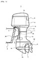
- FIG. 1 is a side view of an outboard motor equipped on a boat
- FIG. 2 is a cross-sectional view illustrating a power transmission mechanism and a contra-rotating propeller mechanism of the outboard motor
- FIG. 3 is an enlarged view illustrating the contra-rotating propeller mechanism
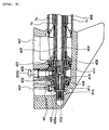
- FIG. 4 is an enlarged view illustrating the power transmission mechanism.
- a boat 1 has a hull 2 with a stern board 2a to which a clamp bracket 4 is secured, and a swivel bracket 5 is attached to the clamp bracket 4 for vertical rotational movement.
- An outboard motor 6 is attached to the swivel bracket 5 for lateral rotational movement.
- the outboard motor 6 has a first propeller 7 and a second propeller 8 arranged in tandem.
- the outboard motor 6 has an upper cowling 9, a bottom cowling 10, and a casing 11.
- An engine 12 is disposed in the upper cowling 9 and the bottom cowling 10.
- the casing 11 is composed of an upper case 13 and a lower case 14, and an upper part of the upper case 13 is covered with an apron 15.
- a power transmission mechanism 20 for transmitting the power of the engine 12 to the second propeller 8 and the first propeller 7, a forward/reverse switching mechanism 30 for shifting between forward, reverse and neutral, and a contra-rotating propeller mechanism 40 for rotating the first propeller 7 and the second propeller 8 in directions opposite to each other.
- the power transmission mechanism 20 has a drive shaft 201 as shown in FIG. 2 , and the drive shaft 201 extends vertically in the upper case 13 and the lower case 14.
- the drive shaft 201 is provided with a transmission ratio changing unit 50 which is configured to change the transmission ratio between the input side and the output side thereof depending on the engine rotational speed or the engine operating conditions.
- a torque converter device 51 is disposed on the input side of the transmission ratio changing unit 50.
- the torque converter device 51 is connected to an input side drive shaft 201a, which is rotatably supported by an exhaust guide 60 and the engine 12 via bearings 61 and 62, respectively.
- the input side drive shaft 201a has a driven gear 202 mounted thereon, and the driven gear 202 is in meshing engagement with a driving gear 203 at the lower end of a crankshaft 16 of the engine 12 so that the power of the engine 12 can be transmitted from the crankshaft 16 to the input side drive shaft 201a.
- the output side of the transmission ratio changing unit 50 is connected to an output side drive shaft 201b.
- the output side drive shaft 201b is rotatably supported by the lower case 14 via a bearing 63, and the output of the transmission ratio changing unit 50 can be transmitted to the contra-rotating propeller mechanism 40.
- the torque converter device 51 is a power transmission device using oil, which is of the type generally known as an automatic transmission, and has an input side shaft 51a connected to the input side drive shaft 201a and an output side shaft 51b connected to an input side shaft 50a of the transmission ratio changing unit 50 as shown in FIG. 4 .
- the transmission ratio changing unit 50 has, as shown in FIG. 5 , a transmission ratio changing planetary gear train including a transmission ratio changing sun gear 50c, transmission ratio changing planetary gears 50d, and a transmission ratio changing internal gear 50e disposed in a housing 50f; an input side shaft 50a connected to the torque converter device 51; and an output side shaft 50b connected to the output side drive shaft 201b.
- the transmission ratio changing sun gear 50c is connected to the housing 50f as a "stationary portion" via a one-way clutch 50g and allowed to rotate in one direction but not in the opposite direction.
- the transmission ratio changing planetary gears 50d and the transmission ratio changing sun gear 50c are configured to integrally engage or disengage via an on-off clutch 50h that is a "multiple-disc clutch”.
- clutch disks 50j of the on-off clutch 50h are brought into pressure engagement with each other to cause the transmission ratio changing planetary gears 50d and the transmission ratio changing sun gear 50c to rotate together.
- the piston 50i is configured to receive hydraulic pressure from an oil pump 50k provided on the input side shaft 50a via a control valve 50m.
- the control valve 50m is controlled by an ECU (engine control unit, not shown) to open and close at predetermined timing.
- the on-off clutch 50h When the on-off clutch 50h is disengaged, the one-way clutch 50g is engaged and the speed from the input side shaft 50a is outputted from the output side shaft 50b with a reduced speed. When the on-off clutch 50h is engaged, the one-way clutch 50g is disengaged and the speed from the input side shaft 50a is outputted from the output side shaft 50b with the same speed.
- the contra-rotating propeller mechanism 40 has two driven gears 401 and 402 for driving the first propeller 7 and the second propeller 8, respectively, and a pinion gear 403 for driving the two driven gears 401 and 402 simultaneously as shown in FIG. 3 .
- the pinion gear 403 is secured to the lower end of the output side drive shaft 201b for rotation therewith and couples the output side of the transmission ratio changing unit 50 to the pinion gear 403.
- Bevel gears are used as the driven gears 401 and 402 and the pinion gear 403, and the pinion gear 403, disposed horizontally, is in meshing engagement with the two driven gears 401 and 402 arranged in an opposed relationship.
- the two driven gears 401 and 402 are supported on a first propeller shaft 404, which extends to the second propeller 8 on the rear side.
- the driven gear 401 is supported on a second propeller shaft 405, which extends to the first propeller 7 on the front side.
- the second propeller shaft 405 has a rear end, protruding backward from the lower case 14, with which the first propeller 7 is integrally formed for rotation therewith, and the first propeller shaft 404 has a rear end, protruding backward from the second propeller shaft 405 behind the first propeller 7, with which the second propeller 8 is integrally formed for rotation therewith.
- the first propeller 7 and the second propeller 8 respectively have inner cylinders 7a and 8a, outer cylinders 7b and 8b, ribs 7c and 8c connecting the inner cylinders 7a and 8a and the outer cylinders 7b and 8b, respectively, and a plurality of vanes 7d and 8d formed integrally with the outer peripheries of the outer cylinders 7b and 8b.
- An exhaust passage 406 is formed between the inner cylinders 7a and 8a and the outer cylinders 7b and 8b, and the exhaust passage 406 is communicated with an exhaust passage 407 formed through the lower case 14.
- the exhaust passage 407 is connected to the exhaust system of the engine 12.
- the driven gear 402, rotatably supported by a bearing 408, is disposed around the front end of the first propeller shaft 404 for free rotation, and the driven gear 401, rotatably supported by a bearing 409, is disposed behind the driven gear 402 and around the front end of the second propeller shaft 405 for free rotation.
- a first slider 410 is in spline engagement with the outer periphery of the front end of the second propeller shaft 405 located inside the paired front and rear driven gears 401 and 402 for back and forth sliding movement along the second propeller shaft 405.
- a second slider 411 is in spline engagement with the outer periphery of the front end of the first propeller shaft 404 located in front of the driven gear 402 for back and forth sliding movement along the first propeller shaft 404.
- a hollow plunger 412 is fitted at the center of the end of the first propeller shaft 404 for back and forth sliding movement, and pins 413 and 414 extending through corresponding slots formed through the first propeller shaft 404 extend perpendicularly through the plunger 412.
- the first slider 410 is connected to the plunger 412 by the pin 413
- the second slider 411 is connected to the plunger 412 by the pin 414.
- the first slider 410 and the second slider 411 are connected to each other by the pins 413 and 414, and are slidable back and forth in the range in which the pins 413 and 414 can move in the slots formed through the first propeller shaft 404.
- a shift cam 426 is attached to the lower end of a shift rod 424 disposed above the second slider 411, and an eccentric pin 426a, which is offset from the central axis (axis of rotation) of the shift rod 424, protrudes from the lower end of the shift cam 426.
- the eccentric pin 426a is in engagement with the outer periphery of the second slider 411.
- the power of the engine 12 is transmitted from the crankshaft 16 to the input side drive shaft 201a, is changed in speed by the transmission ratio changing unit 50, and drives the output side drive shaft 201b to rotate in one direction.
- the rotation of the output side drive shaft 201b is transmitted to the paired front and rear driven gears 401 and 402 via the pinion gear 403, and the two driven gears 401 and 402 are constantly driven to rotate in directions opposite to each other.
- control valve 50m When the transmission ratio changing unit 50 is in its first forward speed mode, the control valve 50m is closed so that no hydraulic pressure may be applied to the piston 50i to allow the transmission ratio changing planetary gears 50d to rotate freely with respect to the transmission ratio changing sun gear 50c as shown in FIG. 7A .
- the transmission ratio changing sun gear 50c is restrained from rotating in the direction by the one-way clutch 50g, the transmission ratio changing planetary gears 50d orbit in the direction of the arrow "b", that is, in the same direction as the transmission ratio changing internal gear 50e, at a rotational speed slower than that of the transmission ratio changing internal gear 50e. Therefore, the output side shaft 50b rotates in the same direction as the input side shaft 50a at a speed slower than that of the input side shaft 50a.
- the control valve 50m When the transmission ratio changing unit 50 is in its second forward speed mode, the control valve 50m is held open so that hydraulic pressure can be applied to the piston 50i to keep the clutch disks 50j in pressure contact with each other as shown in FIG. 7B . Therefore, the transmission ratio changing planetary gears 50d and the transmission ratio changing sun gear 50c are fixed to each other.
- the rotation of the output side drive shaft 201b is transmitted to the second propeller shaft 405 via the pinion gear 403, the driven gear 401 and the first slider 410 and to the first propeller shaft 404 via the pinion gear 403, the driven gear 402 and the second slider 411, and the second propeller shaft 405 and the first propeller 7 secured thereto and the first propeller shaft 404 and the second propeller 8 secured thereto are driven to rotate in directions opposite to each other.
- contra-rotation operation in which the first propeller 7 and the second propeller 8 arranged in tandem are driven to rotate in directions opposite to each other is achieved as described above, and high propulsive efficiency can be achieved by the first propeller 7 and the second propeller 8.
- the first propeller 7' provides high propulsive efficiency and sufficient propulsive force can be achieved.
- a large amount of flue gas exhausted from the high-power engine 12 is discharged into water through the exhaust passage 407 and the exhaust passage 406. Since bubbles of the flue gas are crushed by the first propeller 7 and the second propeller 8 rotating in directions opposite to each other, the influence of the flue gas on the first propeller 7 and the second propeller 8 is very little.
- the transmission ratio changing unit 50 has a transmission ratio changing planetary gear train including the transmission ratio changing sun gear 50c, the transmission ratio changing planetary gears 50d, and the transmission ratio changing internal gear 50e, the transmission ratio can be changed without shutting off power or changing the engagement of gears during the changing operation. Therefore, since the power for driving the propellers is not interrupted, a transmission ratio changing operation can be carried out easily even during acceleration and optimum transmission ratio change timing can be realized in boats, which receive a much larger resistance than land transportation vehicles during traveling.
- the transmission ratio changing unit 50 since the transmission ratio changing unit 50 is provided, satisfactory driving torque characteristics can be achieved by selecting a high transmission ratio especially during traveling at a low speed and the starting and acceleration performance and braking and deceleration performance can be improved dramatically by utilizing its maximum propeller performance.
- the transmission ratio changing unit 50 is located on the drive shaft 201 in the power transmission mechanism 20 in this embodiment, its position is not specifically limited.
- the transmission ratio changing unit 50 may be mounted on an extension of the crankshaft 16.
- the transmission ratio changing unit 50 is not limited to the simple planetary type as shown in FIG. 4 , and various types of planetary gear mechanism such as a dual planetary type can be employed.
- the torque converter device 51 is not limited to a power transmission device using oil.
- FIG. 8 and FIG. 9 show Embodiment 2 of the present invention.
- Embodiment 2 is different from Embodiment 1 in that the torque converter 51 is not provided, that the input side shaft 50a and the output side shaft 50b are disposed coaxially with the crankshaft 16, that not two but only one propeller 7 is provided, and that a dog clutch 415 is provided instead of the first and second sliders 410 and 411.
- FIG. 10 through FIG. 14C show Embodiment 3 of the present invention.
- Embodiment 3 is different from Embodiment 2 in that a shift switching planetary gear train for shift switching is newly provided below the two-speed transmission ratio changing gear train similar to that in Embodiment 2, and that the shift rod 424, the shift cam 426, the eccentric pin 426a, the dog clutch 415 and one of the driven gears, 402, of Embodiment 2 are omitted because the shift switching planetary gear train is provided.
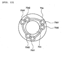
- the shift switching planetary gear train has a shift switching sun gear 70c, first and second shift switching planetary gears 70d1 and 70d2, and a shift switching internal gear 70e as shown in FIG. 11 , FIG. 12 and so on.
- the first and second shift switching planetary gears 70d1 and 70d2 are in meshing engagement with each other as shown in FIG. 13 .
- the first transmission ratio changing planetary gears 70d1 are in meshing engagement with the transmission ratio changing sun gear 70c and the second transmission ratio changing planetary gears 70d2 are in meshing engagement with the transmission ratio changing internal gear 70e.
- the first shift switching planetary gears 70d1 are connected to transmission ratio changing planetary gears 50d of the two-speed transmission ratio changing planetary gear train, and the shift switching sun gear 70c is connected to the output side shaft 50b as shown in FIG. 11 , FIG. 12 and so on.
- the shift switching internal gear 70e of the shift switching planetary gear train is connected to the housing 50f via a first on-off clutch 70h, and the shift switching internal gear 70e and the first and second shift switching planetary gears 70d1 and 70d2 are connected via a second on-off clutch 70i.
- the first on-off clutch 70h and the second on-off clutch 70i have first and second pistons 70j and 70k, respectively, and hydraulic pressure can be applied to the first and second pistons 70j and 70k from an oil pump 50k via a control valve 50m.
- the control valve 50m is connected to an ECU (not shown) and controlled thereby.
- the shift switching sun gear 70c has an output side shaft 50b extending downward therefrom, and the output side shaft 50b is encased in a cylindrical water pump driving shaft 70p.
- the water pump driving shaft 70p is connected to the first and second shift switching planetary gears 70d1 and 70d2.
- a water pump 70q connected to the lower end of the water pump driving shaft 70p supplies cooling water to the engine 12.
- the control valve 50m is so controlled by the ECU as to disengage the first on-off clutch 70h and to engage the second on-off clutch 70i as shown in FIG. 14A .
- the shift switching internal gear 70e, the first and second shift switching planetary gears 70d1 and 70d2 and the shift switching sun gear 70c of the shift switching planetary gear train rotate together in the direction of the arrows in FIG. 14A at the same rotational speed as the two-speed transmission ratio changing planetary gear train side to propel the boat 1 forward.
- the control valve 50m is so controlled by the ECU as to disengage the first and second on-off clutches 70h and 70i as shown in FIG. 14B . Then, each of the shift switching internal gear 70e, the first and second shift switching planetary gears 70d1 and 70d2 and the shift switching sun gear 70c rotates freely. Therefore, even when torque is inputted from the two-speed transmission ratio changing planetary gear train side to the first and second shift switching planetary gears 70d1 and 70d2 side, the power is not transmitted to the output side shaft 50b and a neutral state is established.
- the control valve 50m is so controlled by the ECU as to engage the first on-off clutch 70h and to disengage the second on-off clutch 70h. Then, the shift switching internal gear 70e is fixed to the housing 50f.
- the first and second shift switching planetary gears 70d1 and 70d2 rotate in directions opposite to each other as indicated by the arrows in FIG. 14C while moving inside the shift switching internal gear 70e.
- the shift switching sun gear 70c rotates in a direction (as indicated by the arrow in the drawing) opposite to the rotation direction of the first and second shift switching planetary gears 70d1 and 70d2 (indicated by the arrow in the drawing) to propel the boat 1 backward.
- the water pump driving shaft 70p which is not rotated in the neutral state, is attached to the first and second shift switching planetary gears 70d1 and 70d2 and is always rotated in the same direction. Therefore, the water pump 70q attached to the water pump driving shaft 70p always rotates in the same direction and can constantly fulfill its function as a pump.
- the water pump 70q is of a type which can fulfill the function as a pump while rotating in one direction but not while rotating in the opposite direction.
- the gear trains can be arranged in a more compact manner. Also, since the dog clutch 415, a mechanism for driving the dog clutch 415, the driven gear 402 and so on are not required, the structure can be significantly simplified.
- FIG. 15 shows Embodiment 4 of the present invention.
- This drawing shows the structure of a lower part of an outboard motor 6.
- the structure of the part above the drawing area is the same as that of Embodiment 3 and the outboard motor 6 has a two-speed transmission ratio changing planetary gear train and a shift switching planetary gear train.
- Embodiment 4 is different from Embodiment 3 in that a pair of propellers 7 and 8 rotatable in directions opposite to each other are provided.
- a driven gear 402 on the front side is connected to a first propeller shaft 404 for rotation therewith.
- the first propeller shaft 404 extends to the second propeller 8
- the second propeller 8 is connected to the first propeller shaft 404.
- a driven gear 401 on the rear side is connected to a second propeller shaft 405 for rotation therewith.
- the second propeller shaft 405 extends to the first propeller 7, and the first propeller 7 is connected to the second propeller shaft 405.
- a pinion gear 403 attached to the lower end of an output side drive shaft 201b is in meshing engagement with both the driven gears 401 and 402.
- the driven gears 401 and 402 are rotated in directions opposite to each other to rotate the first and second propellers 7 and 8 in directions opposite to each other.
- the propellers 7 and 8 can be rotated in directions opposite to each other at two different speeds by controlling the two-speed transmission ratio changing planetary gear train, and each of the first and second propellers 7 and 8 can be shifted to a forward state, a neutral state, or a reverse state by controlling the shift switching planetary gear train.
Landscapes
- Chemical & Material Sciences (AREA)
- Engineering & Computer Science (AREA)
- Combustion & Propulsion (AREA)
- Mechanical Engineering (AREA)
- Ocean & Marine Engineering (AREA)
- Structure Of Transmissions (AREA)
Applications Claiming Priority (2)
| Application Number | Priority Date | Filing Date | Title |
|---|---|---|---|
| JP2005205025 | 2005-07-14 | ||
| PCT/JP2006/313675 WO2007007707A1 (ja) | 2005-07-14 | 2006-07-10 | 船外機 |
Publications (3)
| Publication Number | Publication Date |
|---|---|
| EP1902943A1 true EP1902943A1 (de) | 2008-03-26 |
| EP1902943A4 EP1902943A4 (de) | 2009-07-29 |
| EP1902943B1 EP1902943B1 (de) | 2015-09-23 |
Family
ID=37637096
Family Applications (1)
| Application Number | Title | Priority Date | Filing Date |
|---|---|---|---|
| EP06768037.1A Active EP1902943B1 (de) | 2005-07-14 | 2006-07-10 | Aussenbordmotor |
Country Status (4)
| Country | Link |
|---|---|
| US (2) | US8157694B2 (de) |
| EP (1) | EP1902943B1 (de) |
| JP (1) | JPWO2007007707A1 (de) |
| WO (1) | WO2007007707A1 (de) |
Cited By (2)
| Publication number | Priority date | Publication date | Assignee | Title |
|---|---|---|---|---|
| US8109800B2 (en) | 2008-02-08 | 2012-02-07 | Yamaha Hatsudoki Kabushiki Kaisha | Outboard motor |
| US8118701B2 (en) | 2008-02-08 | 2012-02-21 | Yamaha Hatsudoki Kabushiki Kaisha | Outboard motor |
Families Citing this family (60)
| Publication number | Priority date | Publication date | Assignee | Title |
|---|---|---|---|---|
| JPWO2007007707A1 (ja) * | 2005-07-14 | 2009-01-29 | ヤマハマリン株式会社 | 船外機 |
| JP4717718B2 (ja) | 2006-05-25 | 2011-07-06 | 本田技研工業株式会社 | 縦型パワーユニット及び船外機 |
| JP2008223934A (ja) * | 2007-03-14 | 2008-09-25 | Yamaha Marine Co Ltd | 船外機 |
| US7775931B2 (en) * | 2007-03-16 | 2010-08-17 | Gm Global Technology Operations, Inc. | Multi-speed transmission |
| ES2382354T3 (es) * | 2007-05-30 | 2012-06-07 | Schottel Gmbh | Dispositivo de accionamiento por hélice direccional y procedimiento para el mismo |
| JP2009156095A (ja) | 2007-12-25 | 2009-07-16 | Yamaha Motor Co Ltd | 船外機の冷却装置 |
| JP2009160970A (ja) | 2007-12-28 | 2009-07-23 | Yamaha Motor Co Ltd | 船外機 |
| JP2009160969A (ja) | 2007-12-28 | 2009-07-23 | Yamaha Motor Co Ltd | 船外機 |
| JP5160905B2 (ja) | 2008-01-08 | 2013-03-13 | ヤマハ発動機株式会社 | 船外機 |
| JP2009161123A (ja) | 2008-01-09 | 2009-07-23 | Yamaha Motor Co Ltd | 船舶推進機の動力伝達装置における水冷却装置 |
| JP2009166534A (ja) | 2008-01-11 | 2009-07-30 | Yamaha Motor Co Ltd | 船外機 |
| JP2009185972A (ja) * | 2008-02-08 | 2009-08-20 | Yamaha Motor Co Ltd | 船外機 |
| JP5203232B2 (ja) | 2008-05-27 | 2013-06-05 | ヤマハ発動機株式会社 | 船舶推進ユニット |
| JP5192288B2 (ja) * | 2008-05-27 | 2013-05-08 | ヤマハ発動機株式会社 | 船舶推進ユニット |
| US9382973B2 (en) | 2008-10-12 | 2016-07-05 | Christopher C. Sappenfield | Rotary units, rotary mechanisms, and related applications |
| US8668619B2 (en) | 2008-10-12 | 2014-03-11 | Christopher C. Sappenfield | Rotary units, rotary mechanisms, and related applications |
| US8672798B2 (en) | 2008-10-12 | 2014-03-18 | Christopher C. Sappenfield | Rotary units, rotary mechanisms, and related applications |
| US8715133B2 (en) | 2008-10-12 | 2014-05-06 | Christopher C. Sappenfield | Rotary units, rotary mechanisms, and related applications |
| US8672799B2 (en) | 2008-10-12 | 2014-03-18 | Christopher C. Sappenfield | Rotary units, rotary mechanisms, and related applications |
| CN102245935B (zh) * | 2008-10-12 | 2015-04-08 | 克里斯多佛·C·萨彭菲尔德 | 旋转单元、旋转机构以及相关应用 |
| US8834315B2 (en) | 2008-10-12 | 2014-09-16 | Christopher C. Sappenfield | Rotary units, rotary mechanisms, and related applications |
| US9312740B2 (en) | 2008-10-12 | 2016-04-12 | Christopher C. Sappenfield | Apparatus comprising counter-rotational mechanisms and related methods to convey current |
| US8684883B2 (en) | 2008-10-12 | 2014-04-01 | Christopher C. Sappenfield | Handheld devices and related methods |
| US8668618B2 (en) | 2008-10-12 | 2014-03-11 | Christopher C. Sappenfield | Rotary units, rotary mechanisms, and related applications |
| JP4977109B2 (ja) * | 2008-10-20 | 2012-07-18 | 本田技研工業株式会社 | 船外機の制御装置 |
| JP5162408B2 (ja) | 2008-10-20 | 2013-03-13 | 本田技研工業株式会社 | 船外機の制御装置 |
| PT2177429E (pt) * | 2008-10-20 | 2012-12-04 | Honda Motor Co Ltd | Aparelho de controlo de motores fora de borda |
| US8742608B2 (en) * | 2009-03-05 | 2014-06-03 | Tarfin Micu | Drive system for use with flowing fluids |
| JP2010221754A (ja) * | 2009-03-19 | 2010-10-07 | Yamaha Motor Co Ltd | 船外機 |
| US20100248565A1 (en) * | 2009-03-30 | 2010-09-30 | Yamaha Hatsudoki Kabushiki Kaisha | Power transmission system for marine propulsion unit |
| US8337354B2 (en) | 2009-03-30 | 2012-12-25 | Yamaha Hatsudoki Kabushiki Kaisha | Lubricator in power transmission system of marine propulsion unit |
| JP5921335B2 (ja) * | 2012-05-25 | 2016-05-24 | ヤマハ発動機株式会社 | 船舶推進機 |
| JP2014024483A (ja) * | 2012-07-27 | 2014-02-06 | Yamaha Motor Co Ltd | 船舶推進装置 |
| US9718529B2 (en) | 2013-03-15 | 2017-08-01 | Brunswick Corporation | Transmission for marine propulsion |
| US9133910B1 (en) | 2013-03-15 | 2015-09-15 | Brunswick Corporation | Marine transmission with synchronizer to shift into high speed gear |
| JP6156106B2 (ja) * | 2013-12-03 | 2017-07-05 | スズキ株式会社 | 船外機 |
| WO2015159898A1 (ja) * | 2014-04-16 | 2015-10-22 | スズキ株式会社 | 船外機 |
| JP6273991B2 (ja) * | 2014-04-16 | 2018-02-07 | スズキ株式会社 | 船外機 |
| US9676463B1 (en) | 2014-12-30 | 2017-06-13 | Brunswick Corporation | Planetary transmission arrangements for marine propulsion devices |
| US10124874B1 (en) | 2015-01-26 | 2018-11-13 | Brunswick Corporation | Systems and methods for controlling planetary transmission arrangements for marine propulsion devices |
| US9441724B1 (en) | 2015-04-06 | 2016-09-13 | Brunswick Corporation | Method and system for monitoring and controlling a transmission |
| US9759321B1 (en) | 2015-04-08 | 2017-09-12 | Brunswick Corporation | Band brake actuators for actuating band brakes on planetary gearsets in marine propulsion devices |
| US9896175B2 (en) | 2016-06-21 | 2018-02-20 | Robby Galletta Enterprises LLC | Outboard motor and methods of use thereof |
| US10144495B2 (en) | 2016-08-24 | 2018-12-04 | Kanzaki Kokyukoki Manufacturing Co., Ltd. | Outboard motor |
| JP2018047806A (ja) * | 2016-09-21 | 2018-03-29 | 株式会社 神崎高級工機製作所 | 減速逆転機及びこれを備えた船舶 |
| JP2018090199A (ja) * | 2016-12-07 | 2018-06-14 | スズキ株式会社 | 船外機 |
| US10161482B1 (en) | 2016-12-08 | 2018-12-25 | Brunswick Corporation | Planetary transmission arrangements for marine propulsion devices |
| US10077100B1 (en) * | 2016-12-15 | 2018-09-18 | Thomas J. Costello | Propeller driving assembly |
| JP7105554B2 (ja) * | 2017-11-06 | 2022-07-25 | ヤマハ発動機株式会社 | 船外機 |
| US10800502B1 (en) | 2018-10-26 | 2020-10-13 | Brunswick Corporation | Outboard motors having steerable lower gearcase |
| US12304607B1 (en) | 2018-10-26 | 2025-05-20 | Brunswick Corporation | Marine drives having steerable gearcase |
| US11203401B1 (en) * | 2019-07-11 | 2021-12-21 | Brunswick Corporation | Multi-speed transmissions for marine propulsion devices |
| US10995824B1 (en) | 2019-07-16 | 2021-05-04 | Brunswick Corporation | Multi-speed transmissions for marine propulsion devices |
| JP7452214B2 (ja) * | 2020-04-14 | 2024-03-19 | スズキ株式会社 | 船舶推進機 |
| JP2023020371A (ja) * | 2021-07-30 | 2023-02-09 | ヤマハ発動機株式会社 | 船外機 |
| US12600450B2 (en) | 2022-03-28 | 2026-04-14 | Brunswick Corporation | Stern drives having steerable gearcase |
| US12539952B2 (en) | 2022-03-28 | 2026-02-03 | Brunswick Corporation | Marine drives having hydraulically actuated steerable gearcase |
| US12304609B2 (en) | 2022-03-28 | 2025-05-20 | Brunswick Corporation | Stern drives and transom bracket assemblies for stern drives providing vibration isolation |
| US12606289B2 (en) | 2022-03-28 | 2026-04-21 | Brunswick Corporation | Stern drives and methods of installing stern drives |
| US12545391B2 (en) | 2022-03-28 | 2026-02-10 | Brunswick Corporation | Stern drives and noise-vibration-harshness dampening assemblies for a stern drives |
Family Cites Families (32)
| Publication number | Priority date | Publication date | Assignee | Title |
|---|---|---|---|---|
| GB600790A (en) * | 1943-03-26 | 1948-04-19 | Applic Des Brevets Cotal Soc D | Improvements relating to combined reversing and change-speed gearing |
| US2688298A (en) * | 1951-02-26 | 1954-09-07 | Hart Carter Co | Reversible outboard motor with hydraulic control |
| US2751799A (en) * | 1951-02-26 | 1956-06-26 | Hart Carter Co | Forward and reverse planetary transmission |
| GB833343A (en) * | 1955-02-14 | 1960-04-21 | Reiners Walter | Improvements in driving and steering ships with steering propellers |
| DE1530584B1 (de) * | 1965-06-12 | 1970-07-16 | Daimler Benz Ag | Aus mindestens zwei Umlaufräder-Getrieben aufgebautes Kraftfahrzeug-Wechselgetriebe |
| US3404586A (en) * | 1966-04-28 | 1968-10-08 | William G. Fanstone | Outboard motor transmission |
| DE3102556A1 (de) * | 1981-01-27 | 1982-08-05 | Mtu Motoren- Und Turbinen-Union Friedrichshafen Gmbh, 7990 Friedrichshafen | "schaltbares stufengetriebe" |
| JPS62191297A (ja) * | 1986-02-17 | 1987-08-21 | Honda Motor Co Ltd | 船外機 |
| US4850911A (en) * | 1986-05-15 | 1989-07-25 | Sanshin Kogyo Kabushiki Kaisha | Power transmission device for inboard/outboard system |
| JP2629192B2 (ja) * | 1987-08-05 | 1997-07-09 | トヨタ自動車株式会社 | 遊星歯車式変速装置 |
| JP2686517B2 (ja) * | 1988-04-25 | 1997-12-08 | スズキ株式会社 | 船外機 |
| JP2785200B2 (ja) * | 1989-03-30 | 1998-08-13 | スズキ株式会社 | 船外機用変速装置 |
| JPH03121362A (ja) * | 1989-10-02 | 1991-05-23 | Aisin Aw Co Ltd | 自動変速機の制御装置 |
| US5403218A (en) * | 1992-11-20 | 1995-04-04 | Sanshin Kogyo Kabushiki Kaisha | Shifting mechanism for outboard drive |
| JPH06156382A (ja) * | 1992-11-28 | 1994-06-03 | Sanshin Ind Co Ltd | 船舶推進機の前後進切換装置 |
| JPH07144695A (ja) | 1993-11-22 | 1995-06-06 | Sanshin Ind Co Ltd | 船舶推進装置の排気構造 |
| US5564992A (en) * | 1994-03-31 | 1996-10-15 | Cunningham; James T. | Torque maximizing controlled slip gear drive |
| JPH09263294A (ja) | 1996-03-29 | 1997-10-07 | Sanshin Ind Co Ltd | 船舶の推進機 |
| JPH09301288A (ja) * | 1996-05-13 | 1997-11-25 | Sanshin Ind Co Ltd | 推進機 |
| US5791950A (en) * | 1996-12-05 | 1998-08-11 | Brunswick Corporation | Twin propeller marine propulsion unit |
| SE513265C2 (sv) * | 1998-12-16 | 2000-08-14 | Volvo Penta Ab | Båtpropellertransmission |
| JP2001039393A (ja) * | 1999-07-29 | 2001-02-13 | Aisin Seiki Co Ltd | 船内外機 |
| US6435923B1 (en) * | 2000-04-05 | 2002-08-20 | Bombardier Motor Corporation Of America | Two speed transmission with reverse for a watercraft |
| US6350165B1 (en) * | 2000-06-21 | 2002-02-26 | Bombardier Motor Corporation Of America | Marine stern drive two-speed transmission |
| US6517395B1 (en) * | 2000-11-27 | 2003-02-11 | Bombardier Motor Corporation Of America | Drive train with a single diametral pitch pinion driving two gears with different diametral pitches |
| DE20021586U1 (de) * | 2000-12-21 | 2002-02-14 | Andreas Stihl AG & Co., 71336 Waiblingen | Getriebekopf |
| JP3736386B2 (ja) * | 2001-05-14 | 2006-01-18 | 日産自動車株式会社 | 自動変速機の伝動機構 |
| JP4386672B2 (ja) * | 2003-05-19 | 2009-12-16 | 本田技研工業株式会社 | 自動変速機 |
| JP3941058B2 (ja) * | 2003-06-12 | 2007-07-04 | 本田技研工業株式会社 | 駆動装置 |
| WO2005102836A1 (en) * | 2004-04-22 | 2005-11-03 | Nautitech Pty Ltd | Decoupler |
| JPWO2007007707A1 (ja) * | 2005-07-14 | 2009-01-29 | ヤマハマリン株式会社 | 船外機 |
| JP2008223934A (ja) * | 2007-03-14 | 2008-09-25 | Yamaha Marine Co Ltd | 船外機 |
-
2006
- 2006-07-10 JP JP2006552411A patent/JPWO2007007707A1/ja active Pending
- 2006-07-10 WO PCT/JP2006/313675 patent/WO2007007707A1/ja not_active Ceased
- 2006-07-10 EP EP06768037.1A patent/EP1902943B1/de active Active
-
2007
- 2007-09-14 US US11/855,991 patent/US8157694B2/en active Active
-
2008
- 2008-05-28 US US12/127,866 patent/US7704183B2/en active Active
Cited By (2)
| Publication number | Priority date | Publication date | Assignee | Title |
|---|---|---|---|---|
| US8109800B2 (en) | 2008-02-08 | 2012-02-07 | Yamaha Hatsudoki Kabushiki Kaisha | Outboard motor |
| US8118701B2 (en) | 2008-02-08 | 2012-02-21 | Yamaha Hatsudoki Kabushiki Kaisha | Outboard motor |
Also Published As
| Publication number | Publication date |
|---|---|
| EP1902943B1 (de) | 2015-09-23 |
| EP1902943A4 (de) | 2009-07-29 |
| JPWO2007007707A1 (ja) | 2009-01-29 |
| WO2007007707A1 (ja) | 2007-01-18 |
| US7704183B2 (en) | 2010-04-27 |
| US8157694B2 (en) | 2012-04-17 |
| US20080233815A1 (en) | 2008-09-25 |
| US20080070739A1 (en) | 2008-03-20 |
Similar Documents
| Publication | Publication Date | Title |
|---|---|---|
| EP1902943B1 (de) | Aussenbordmotor | |
| US8105199B2 (en) | Outboard motor | |
| JP2009185972A (ja) | 船外機 | |
| US4820209A (en) | Torque converter marine transmission with variable power output | |
| EP1789313B1 (de) | Entkoppler | |
| US7621792B2 (en) | Outboard motor | |
| EP3168134B1 (de) | Leistungsgetriebevorrichtung und verfahren für einen aussenbordmotor | |
| JPH03273995A (ja) | 船舶推進機の倍力機構 | |
| JP2001039393A (ja) | 船内外機 | |
| US6196887B1 (en) | Marine drive transmission | |
| US5813887A (en) | Marine propulsion system | |
| US7384320B2 (en) | Power train of a marine transport vessel | |
| CN214383666U (zh) | 一种紧凑型变速起锚机 | |
| JP2686622B2 (ja) | 遊星歯車式前進二速減速逆転機 | |
| US3532068A (en) | Propulsion of a boat | |
| JPH0577788A (ja) | 舶用減速逆転機構 | |
| EP4481221A1 (de) | Hybrider endlosdirektantrieb | |
| JPH0781684A (ja) | 船舶推進装置 | |
| JP3695647B2 (ja) | 船外機 | |
| JP6430895B2 (ja) | マリンギア装置 | |
| JP2686621B2 (ja) | 遊星歯車式前進二速減速逆転機 | |
| CA2390818C (en) | Marine propulsion system | |
| WO2005120944A1 (en) | Stern tube integrated gear for contra rotating variable pitch propellers | |
| JPH09301282A (ja) | 船舶推進装置 |
Legal Events
| Date | Code | Title | Description |
|---|---|---|---|
| PUAI | Public reference made under article 153(3) epc to a published international application that has entered the european phase |
Free format text: ORIGINAL CODE: 0009012 |
|
| 17P | Request for examination filed |
Effective date: 20070802 |
|
| AK | Designated contracting states |
Kind code of ref document: A1 Designated state(s): AT BE BG CH CY CZ DE DK EE ES FI FR GB GR HU IE IS IT LI LT LU LV MC NL PL PT RO SE SI SK TR |
|
| DAX | Request for extension of the european patent (deleted) | ||
| A4 | Supplementary search report drawn up and despatched |
Effective date: 20090630 |
|
| RIC1 | Information provided on ipc code assigned before grant |
Ipc: F16H 3/58 20060101ALI20090623BHEP Ipc: B63H 23/30 20060101ALI20090623BHEP Ipc: B63H 20/14 20060101AFI20070312BHEP Ipc: B63H 5/10 20060101ALI20090623BHEP Ipc: F16H 3/18 20060101ALI20090623BHEP Ipc: F16H 47/04 20060101ALI20090623BHEP |
|
| RAP1 | Party data changed (applicant data changed or rights of an application transferred) |
Owner name: YAMAHA HATSUDOKI KABUSHIKI KAISHA |
|
| DAX | Request for extension of the european patent (deleted) | ||
| 17Q | First examination report despatched |
Effective date: 20150303 |
|
| GRAP | Despatch of communication of intention to grant a patent |
Free format text: ORIGINAL CODE: EPIDOSNIGR1 |
|
| INTG | Intention to grant announced |
Effective date: 20150422 |
|
| GRAS | Grant fee paid |
Free format text: ORIGINAL CODE: EPIDOSNIGR3 |
|
| GRAA | (expected) grant |
Free format text: ORIGINAL CODE: 0009210 |
|
| AK | Designated contracting states |
Kind code of ref document: B1 Designated state(s): AT BE BG CH CY CZ DE DK EE ES FI FR GB GR HU IE IS IT LI LT LU LV MC NL PL PT RO SE SI SK TR |
|
| REG | Reference to a national code |
Ref country code: GB Ref legal event code: FG4D |
|
| REG | Reference to a national code |
Ref country code: CH Ref legal event code: EP |
|
| REG | Reference to a national code |
Ref country code: AT Ref legal event code: REF Ref document number: 751073 Country of ref document: AT Kind code of ref document: T Effective date: 20151015 |
|
| REG | Reference to a national code |
Ref country code: IE Ref legal event code: FG4D |
|
| REG | Reference to a national code |
Ref country code: DE Ref legal event code: R096 Ref document number: 602006046751 Country of ref document: DE |
|
| REG | Reference to a national code |
Ref country code: NL Ref legal event code: MP Effective date: 20150923 |
|
| PG25 | Lapsed in a contracting state [announced via postgrant information from national office to epo] |
Ref country code: LV Free format text: LAPSE BECAUSE OF FAILURE TO SUBMIT A TRANSLATION OF THE DESCRIPTION OR TO PAY THE FEE WITHIN THE PRESCRIBED TIME-LIMIT Effective date: 20150923 Ref country code: FI Free format text: LAPSE BECAUSE OF FAILURE TO SUBMIT A TRANSLATION OF THE DESCRIPTION OR TO PAY THE FEE WITHIN THE PRESCRIBED TIME-LIMIT Effective date: 20150923 Ref country code: GR Free format text: LAPSE BECAUSE OF FAILURE TO SUBMIT A TRANSLATION OF THE DESCRIPTION OR TO PAY THE FEE WITHIN THE PRESCRIBED TIME-LIMIT Effective date: 20151224 Ref country code: LT Free format text: LAPSE BECAUSE OF FAILURE TO SUBMIT A TRANSLATION OF THE DESCRIPTION OR TO PAY THE FEE WITHIN THE PRESCRIBED TIME-LIMIT Effective date: 20150923 |
|
| REG | Reference to a national code |
Ref country code: LT Ref legal event code: MG4D |
|
| REG | Reference to a national code |
Ref country code: AT Ref legal event code: MK05 Ref document number: 751073 Country of ref document: AT Kind code of ref document: T Effective date: 20150923 |
|
| PG25 | Lapsed in a contracting state [announced via postgrant information from national office to epo] |
Ref country code: SE Free format text: LAPSE BECAUSE OF FAILURE TO SUBMIT A TRANSLATION OF THE DESCRIPTION OR TO PAY THE FEE WITHIN THE PRESCRIBED TIME-LIMIT Effective date: 20150923 |
|
| PG25 | Lapsed in a contracting state [announced via postgrant information from national office to epo] |
Ref country code: NL Free format text: LAPSE BECAUSE OF FAILURE TO SUBMIT A TRANSLATION OF THE DESCRIPTION OR TO PAY THE FEE WITHIN THE PRESCRIBED TIME-LIMIT Effective date: 20150923 |
|
| PG25 | Lapsed in a contracting state [announced via postgrant information from national office to epo] |
Ref country code: CZ Free format text: LAPSE BECAUSE OF FAILURE TO SUBMIT A TRANSLATION OF THE DESCRIPTION OR TO PAY THE FEE WITHIN THE PRESCRIBED TIME-LIMIT Effective date: 20150923 Ref country code: EE Free format text: LAPSE BECAUSE OF FAILURE TO SUBMIT A TRANSLATION OF THE DESCRIPTION OR TO PAY THE FEE WITHIN THE PRESCRIBED TIME-LIMIT Effective date: 20150923 Ref country code: ES Free format text: LAPSE BECAUSE OF FAILURE TO SUBMIT A TRANSLATION OF THE DESCRIPTION OR TO PAY THE FEE WITHIN THE PRESCRIBED TIME-LIMIT Effective date: 20150923 Ref country code: IS Free format text: LAPSE BECAUSE OF FAILURE TO SUBMIT A TRANSLATION OF THE DESCRIPTION OR TO PAY THE FEE WITHIN THE PRESCRIBED TIME-LIMIT Effective date: 20160123 Ref country code: SK Free format text: LAPSE BECAUSE OF FAILURE TO SUBMIT A TRANSLATION OF THE DESCRIPTION OR TO PAY THE FEE WITHIN THE PRESCRIBED TIME-LIMIT Effective date: 20150923 |
|
| PG25 | Lapsed in a contracting state [announced via postgrant information from national office to epo] |
Ref country code: AT Free format text: LAPSE BECAUSE OF FAILURE TO SUBMIT A TRANSLATION OF THE DESCRIPTION OR TO PAY THE FEE WITHIN THE PRESCRIBED TIME-LIMIT Effective date: 20150923 Ref country code: PL Free format text: LAPSE BECAUSE OF FAILURE TO SUBMIT A TRANSLATION OF THE DESCRIPTION OR TO PAY THE FEE WITHIN THE PRESCRIBED TIME-LIMIT Effective date: 20150923 Ref country code: PT Free format text: LAPSE BECAUSE OF FAILURE TO SUBMIT A TRANSLATION OF THE DESCRIPTION OR TO PAY THE FEE WITHIN THE PRESCRIBED TIME-LIMIT Effective date: 20160125 Ref country code: RO Free format text: LAPSE BECAUSE OF FAILURE TO SUBMIT A TRANSLATION OF THE DESCRIPTION OR TO PAY THE FEE WITHIN THE PRESCRIBED TIME-LIMIT Effective date: 20150923 |
|
| REG | Reference to a national code |
Ref country code: DE Ref legal event code: R097 Ref document number: 602006046751 Country of ref document: DE |
|
| REG | Reference to a national code |
Ref country code: FR Ref legal event code: PLFP Year of fee payment: 11 |
|
| PLBE | No opposition filed within time limit |
Free format text: ORIGINAL CODE: 0009261 |
|
| STAA | Information on the status of an ep patent application or granted ep patent |
Free format text: STATUS: NO OPPOSITION FILED WITHIN TIME LIMIT |
|
| 26N | No opposition filed |
Effective date: 20160624 |
|
| PG25 | Lapsed in a contracting state [announced via postgrant information from national office to epo] |
Ref country code: DK Free format text: LAPSE BECAUSE OF FAILURE TO SUBMIT A TRANSLATION OF THE DESCRIPTION OR TO PAY THE FEE WITHIN THE PRESCRIBED TIME-LIMIT Effective date: 20150923 |
|
| PG25 | Lapsed in a contracting state [announced via postgrant information from national office to epo] |
Ref country code: SI Free format text: LAPSE BECAUSE OF FAILURE TO SUBMIT A TRANSLATION OF THE DESCRIPTION OR TO PAY THE FEE WITHIN THE PRESCRIBED TIME-LIMIT Effective date: 20150923 |
|
| PG25 | Lapsed in a contracting state [announced via postgrant information from national office to epo] |
Ref country code: BE Free format text: LAPSE BECAUSE OF FAILURE TO SUBMIT A TRANSLATION OF THE DESCRIPTION OR TO PAY THE FEE WITHIN THE PRESCRIBED TIME-LIMIT Effective date: 20150923 |
|
| REG | Reference to a national code |
Ref country code: CH Ref legal event code: PL |
|
| GBPC | Gb: european patent ceased through non-payment of renewal fee |
Effective date: 20160710 |
|
| PG25 | Lapsed in a contracting state [announced via postgrant information from national office to epo] |
Ref country code: MC Free format text: LAPSE BECAUSE OF FAILURE TO SUBMIT A TRANSLATION OF THE DESCRIPTION OR TO PAY THE FEE WITHIN THE PRESCRIBED TIME-LIMIT Effective date: 20150923 |
|
| PG25 | Lapsed in a contracting state [announced via postgrant information from national office to epo] |
Ref country code: LI Free format text: LAPSE BECAUSE OF NON-PAYMENT OF DUE FEES Effective date: 20160731 Ref country code: CH Free format text: LAPSE BECAUSE OF NON-PAYMENT OF DUE FEES Effective date: 20160731 |
|
| REG | Reference to a national code |
Ref country code: IE Ref legal event code: MM4A |
|
| PG25 | Lapsed in a contracting state [announced via postgrant information from national office to epo] |
Ref country code: GB Free format text: LAPSE BECAUSE OF NON-PAYMENT OF DUE FEES Effective date: 20160710 |
|
| REG | Reference to a national code |
Ref country code: FR Ref legal event code: PLFP Year of fee payment: 12 |
|
| PG25 | Lapsed in a contracting state [announced via postgrant information from national office to epo] |
Ref country code: IE Free format text: LAPSE BECAUSE OF NON-PAYMENT OF DUE FEES Effective date: 20160710 |
|
| PG25 | Lapsed in a contracting state [announced via postgrant information from national office to epo] |
Ref country code: LU Free format text: LAPSE BECAUSE OF NON-PAYMENT OF DUE FEES Effective date: 20160710 |
|
| PG25 | Lapsed in a contracting state [announced via postgrant information from national office to epo] |
Ref country code: HU Free format text: LAPSE BECAUSE OF FAILURE TO SUBMIT A TRANSLATION OF THE DESCRIPTION OR TO PAY THE FEE WITHIN THE PRESCRIBED TIME-LIMIT; INVALID AB INITIO Effective date: 20060710 Ref country code: CY Free format text: LAPSE BECAUSE OF FAILURE TO SUBMIT A TRANSLATION OF THE DESCRIPTION OR TO PAY THE FEE WITHIN THE PRESCRIBED TIME-LIMIT Effective date: 20150923 |
|
| PG25 | Lapsed in a contracting state [announced via postgrant information from national office to epo] |
Ref country code: TR Free format text: LAPSE BECAUSE OF FAILURE TO SUBMIT A TRANSLATION OF THE DESCRIPTION OR TO PAY THE FEE WITHIN THE PRESCRIBED TIME-LIMIT Effective date: 20150923 |
|
| REG | Reference to a national code |
Ref country code: FR Ref legal event code: PLFP Year of fee payment: 13 |
|
| PG25 | Lapsed in a contracting state [announced via postgrant information from national office to epo] |
Ref country code: BG Free format text: LAPSE BECAUSE OF FAILURE TO SUBMIT A TRANSLATION OF THE DESCRIPTION OR TO PAY THE FEE WITHIN THE PRESCRIBED TIME-LIMIT Effective date: 20150923 |
|
| P01 | Opt-out of the competence of the unified patent court (upc) registered |
Effective date: 20230527 |
|
| PGFP | Annual fee paid to national office [announced via postgrant information from national office to epo] |
Ref country code: DE Payment date: 20250722 Year of fee payment: 20 |
|
| PGFP | Annual fee paid to national office [announced via postgrant information from national office to epo] |
Ref country code: IT Payment date: 20250724 Year of fee payment: 20 |
|
| PGFP | Annual fee paid to national office [announced via postgrant information from national office to epo] |
Ref country code: FR Payment date: 20250724 Year of fee payment: 20 |