EP1902989B1 - Vorrichtung zum Entstapeln von Postsendungen mit optimierter Verwaltung der Entstapelbedingungen - Google Patents
Vorrichtung zum Entstapeln von Postsendungen mit optimierter Verwaltung der Entstapelbedingungen Download PDFInfo
- Publication number
- EP1902989B1 EP1902989B1 EP07116139A EP07116139A EP1902989B1 EP 1902989 B1 EP1902989 B1 EP 1902989B1 EP 07116139 A EP07116139 A EP 07116139A EP 07116139 A EP07116139 A EP 07116139A EP 1902989 B1 EP1902989 B1 EP 1902989B1
- Authority
- EP
- European Patent Office
- Prior art keywords
- unstacking
- sensor
- head
- unstacking head
- sensors
- Prior art date
- Legal status (The legal status is an assumption and is not a legal conclusion. Google has not performed a legal analysis and makes no representation as to the accuracy of the status listed.)
- Not-in-force
Links
- 238000007726 management method Methods 0.000 title 1
- 238000012384 transportation and delivery Methods 0.000 title 1
- 238000001514 detection method Methods 0.000 claims abstract description 6
- 230000004044 response Effects 0.000 claims abstract description 5
- 230000003287 optical effect Effects 0.000 claims description 6
- 230000008859 change Effects 0.000 claims description 3
- 230000004888 barrier function Effects 0.000 claims description 2
- 239000002184 metal Substances 0.000 claims 1
- 238000000605 extraction Methods 0.000 abstract 1
- 238000012937 correction Methods 0.000 description 21
- 238000000034 method Methods 0.000 description 19
- 230000008569 process Effects 0.000 description 19
- 230000000694 effects Effects 0.000 description 6
- 230000006866 deterioration Effects 0.000 description 4
- 238000012545 processing Methods 0.000 description 4
- 210000002457 barrier cell Anatomy 0.000 description 3
- 238000011144 upstream manufacturing Methods 0.000 description 3
- 238000006073 displacement reaction Methods 0.000 description 2
- 238000012015 optical character recognition Methods 0.000 description 2
- 238000011084 recovery Methods 0.000 description 2
- 230000007704 transition Effects 0.000 description 2
- 230000009471 action Effects 0.000 description 1
- 210000004027 cell Anatomy 0.000 description 1
- 230000002301 combined effect Effects 0.000 description 1
- 230000000295 complement effect Effects 0.000 description 1
- 230000002951 depilatory effect Effects 0.000 description 1
- 229920001971 elastomer Polymers 0.000 description 1
- 239000000806 elastomer Substances 0.000 description 1
- 108010084652 homeobox protein PITX1 Proteins 0.000 description 1
- 238000012423 maintenance Methods 0.000 description 1
- 239000000463 material Substances 0.000 description 1
- 238000002360 preparation method Methods 0.000 description 1
- 238000000926 separation method Methods 0.000 description 1
- 230000001360 synchronised effect Effects 0.000 description 1
- 238000012549 training Methods 0.000 description 1
- 230000001960 triggered effect Effects 0.000 description 1
Images


Classifications
-
- B—PERFORMING OPERATIONS; TRANSPORTING
- B65—CONVEYING; PACKING; STORING; HANDLING THIN OR FILAMENTARY MATERIAL
- B65H—HANDLING THIN OR FILAMENTARY MATERIAL, e.g. SHEETS, WEBS, CABLES
- B65H3/00—Separating articles from piles
- B65H3/08—Separating articles from piles using pneumatic force
- B65H3/12—Suction bands, belts, or tables moving relatively to the pile
- B65H3/124—Suction bands or belts
-
- B—PERFORMING OPERATIONS; TRANSPORTING
- B65—CONVEYING; PACKING; STORING; HANDLING THIN OR FILAMENTARY MATERIAL
- B65H—HANDLING THIN OR FILAMENTARY MATERIAL, e.g. SHEETS, WEBS, CABLES
- B65H3/00—Separating articles from piles
- B65H3/46—Supplementary devices or measures to assist separation or prevent double feed
-
- B—PERFORMING OPERATIONS; TRANSPORTING
- B65—CONVEYING; PACKING; STORING; HANDLING THIN OR FILAMENTARY MATERIAL
- B65H—HANDLING THIN OR FILAMENTARY MATERIAL, e.g. SHEETS, WEBS, CABLES
- B65H2511/00—Dimensions; Position; Numbers; Identification; Occurrences
- B65H2511/50—Occurence
- B65H2511/51—Presence
- B65H2511/514—Particular portion of element
-
- B—PERFORMING OPERATIONS; TRANSPORTING
- B65—CONVEYING; PACKING; STORING; HANDLING THIN OR FILAMENTARY MATERIAL
- B65H—HANDLING THIN OR FILAMENTARY MATERIAL, e.g. SHEETS, WEBS, CABLES
- B65H2701/00—Handled material; Storage means
- B65H2701/10—Handled articles or webs
- B65H2701/19—Specific article or web
- B65H2701/1916—Envelopes and articles of mail
Definitions
- the invention relates to a device for unstacking flat objects comprising a power supply magazine controlled to move flat objects in stack on edge facing an unstacking head with a motorized drive.
- the motorized drive comprising a perforated band and a vacuum chamber is operated to separate a first current object from the stack and drive it in a direction transverse to the moving direction of the stack of flat objects.
- the invention more particularly relates to a device for unstacking postal items, such as letters and flat objects of large format, in a postal sorting machine for example.
- the main magazine 1 comprises in particular a belt conveyor 2 with a motorized drive on which an operator has the postal items 3 in stack on edge and a pallet 4 also with a motorized drive which extends in a substantially vertical plane and which is moved to push the back of the stack in the direction indicated by the arrow 6 facing the unstacking head 5.
- the postal items of the stack are held laterally by a jogging edge 7 which extends in a substantially vertical plane along an edge of the belt conveyor 2.
- the substantially flat unstacking head 5 extends in a vertical plane transverse to the direction indicated by the arrow 6 for moving the stack of items 3 on the belt conveyor 2 and is capable of separating the first current item at the front of the stack in the transverse direction indicated by the perpendicular arrow 8 at the arrow 6.
- the unstacking head 5 comprises two substantially rectangular openings in which a perforated strip 9 and one or more vacuum chambers or suction nozzles (not shown) are driven by a motor, cooperating to suck up the first shipment of the stack and to move it in the direction indicated by the arrow 8.
- the stack of postal items 3 disposed in the main magazine 1 is moved by the motorized stepper type drives of the belt conveyor 2 and the pallet 4 which are actuated at the same speed.
- the first shipment to the front of the stack of mail is thus brought to bear against the unstacking head 5 so that this current mail piece of the stack is pressed against the unstacking head 5 and is separated from the stack by the combined effect of suction
- the mailpiece is then clamped between two deformable wheels 10 arranged in the extension of the head 5.
- These wheels 10 are motorized to convey the current shipment downstream of the unstacking device. They consist of an elastomer material elastically deformable so as to be able to adapt to different thicknesses of postal items.
- This unstacking process is repeated as a new mailing at the front of the pile is presented in front of the unstacking head 5.
- the postal items of the stack are serialized continuously, that is to say with a constant unstacking rate.
- the unstacker feeding device similar to that described above further comprises a motorized chute.
- the fall motorized is arranged between the belt conveyor and the unstacking head.
- the presence of this motorized fall has the effect of presenting in fan a number of first postal items (those arranged in the fall) which has the consequence that the first mailing to the front of the pile is loosened other shipments and therefore has more facility to present itself adequately against the unstacking head 5.
- the patent document WO2005 / 042386 discloses a device for unstacking postal items of the "tiler" type which is provided with a main magazine comprising a main belt conveyor and a pallet and a secondary conveyor disposed between the main conveyor and the unstacking head.
- the unstacking head comprises a band with a motorized drive actuated to separate a first current shipment from the stack and drive it in a direction transverse to the direction of travel of the mail stack.
- the strip of the unstacking head does not cooperate with a vacuum chamber since the items are moved on one another so as to form a tiled pattern during the unstacking process.
- sensors arranged in the unstacking head make it possible to detect the inclination of the current mailpiece to be unstacked and in response to the signals supplied by its sensors the main belt conveyor, the pallet or the secondary conveyor are controlled to correct the tilt.
- the motorized drive of the unstacking head is actuated and stopped so as to obtain a constant pitch between postal items at the output of the unstacking device.
- Document is also known US2002 / 153654 a device for unstacking flat objects with a control of the presentation of the objects in front of an unstacking head, comprising one or two sensors arranged in the unstacking head. Said command stops driving the unstacking head when the one or both sensors determine an inadequate presentation of an object. The unstacking of said object is activated when the presentation of the object becomes adequate, after correction of the presentation of the object.
- this device an ineligible number of shipments are deteriorated and stuffing situations are frequent.
- the object of the present invention is therefore to further improve a device for unstacking flat objects to prevent deterioration of these flat objects and the stuffing of the unstacking device
- the subject of the invention is a device for unstacking flat objects comprising the features of claim 1.
- the first sensor is a flag mechanical sensor
- the second sensor is a reflection optical sensor
- the third sensor is a reflection optical sensor
- the fourth sensor is an optical barrier sensor the first, second and third sensors are aligned vertically in the unstacking head.
- the feed magazine comprises a chute arranged between a main conveyor with a motorized drive and the unstacking head and a pallet with a motorized drive, said pallet being able to be moved along the main conveyor, the chute being provided with secondary conveyors with a motorized drive, the control unit acting on the motorized drives of the main conveyor, the pallet and the secondary conveyors to adequately present the current object in relation to the main conveyor at the unstacking head.
- main conveyor, the motorized pallet and the secondary conveyors in the chute are provided to be asynchronously controlled by the control unit which is further arranged to change the speed and direction of the motorized drives of the store. power supply to present the current object adequately.
- control unit is arranged to trigger an alarm at the end of a certain period during which the control unit 13 acts on the motorized drives of the main conveyor, of the the pallet and secondary conveyors without obtaining an adequate presentation of the current object with respect to the unstacking head.
- the invention extends to a machine for processing postal items comprising such an unstacking device.
- the feeding device applies to flat objects, for example small and large format flat mailpieces, but can also find application in other areas of processing of flat objects such as books, books and magazines. checks or other.
- the figure 1 schematically illustrates a feeding device for a unstacker of flat mail items according to the state of the art.
- the figure 2 schematically illustrates a feeding device for a unstacker flat mail items according to the invention.
- the figure 3 is a flow chart illustrating the different steps of the signal control process provided by the sensors.
- the figure 4 schematically illustrates the unstacking face with the sensors including the flag mechanical sensor.
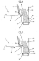
- the figure 5 illustrates a first situation of inadequate presentation of the current shipment relative to the unstacking head.
- the figure 6 illustrates a second situation of inadequate presentation of the current shipment relative to the unstacking head.
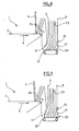
- the figure 7 illustrates a third situation of inadequate presentation of the current shipment relative to the unstacking head.
- the figure 8 illustrates a fourth situation of inadequate presentation of the current mail with respect to the unstacking head.
- the figure 9 illustrates a fifth situation of inadequate presentation of the current shipment relative to the unstacking head.
- the figure 10 illustrates a sixth situation of inadequate presentation of the current shipment relative to the unstacking head.
- the figure 11 illustrates a seventh situation of inadequate presentation of the current mail with respect to the unstacking head.
- the figure 12 illustrates in the form of a table the signals of the sensors detecting an unsuitable presentation of the current item to be unstacked.
- the figure 2 illustrates therefore a destacking device 1 of postal items according to the invention, such as letters and flat postal objects called large format, the elements common with that of the figure 1 carry identical numerical references.
- This unstacking device is used to serialize shipments upstream of serial conveyors of postal items in which the items are separated in pairs with a normally constant pitch.
- the motorized drives of the deformable wheels 10 between which are clamped serialized shipments can be controlled at a variable speed to catch up if necessary gaps between consecutive shipments.
- This variable speed arrangement constitutes a synchronization system ensuring a constant pitch.
- this synchronization system authorizes the performance of certain correction operations during a time window T compatible with the requirement of a constant pitch between consecutive items at the output of the unstacking device.
- the unstacking device 1 comprises a main feed magazine 1 with a belt conveyor 2 with a motorized drive on which postal items 3 are arranged in stack on edge at the front of a pallet 4 with a motorized drive which s extends substantially in a vertical plane by being slightly inclined to support the rear of the mail stack.
- the belt conveyor 2 and the pallet 4 move the stack of items 3 on edge in the direction of the unstacking head 5 in the direction 6.
- a chute 11 in the form of a gutter, constituting a secondary feed store between the end of the main conveyor 2 and the unstacking head 5.
- the bottom of the chute 11 is located at a depth of about 100 mm below the upper surface of the conveyor 2 and has a width of about 98 mm in the direction 6.
- the bottom of this chute 11 is provided with a set of secondary conveyors 12 with a motorized drive, for example here four belt conveyors, which move the shipments on edge in the chute in the direction 6 towards the unstacking head 5 .
- a motorized drive for example here four belt conveyors, which move the shipments on edge in the chute in the direction 6 towards the unstacking head 5 .
- the unstacking head 5 with a motorized drive extends vertically from the bottom of the chute 11 to a sufficient height corresponding at least to the maximum height of the postal items to be unstacked.
- the unstacking head 5 in the form of a sheet is provided here with two rectangular openings arranged side by side in the direction 8.
- an endless perforated strip 9 cooperates with vacuum chambers or nozzles suction (not shown) to enter and move in the direction 8 a current shipment of the stack facing the head.
- the motorized drives of the belt conveyor 2, the pallet 4, the secondary conveyors 12 and the unstacking head (perforated strips 9 and suction nozzles) are provided to be controlled independently of each other. others but can of course be synchronized with each other by a control unit 13, for example a programmable data processing processor.
- the unstacking device comprises a set of sensors which each provide a detection signal to the control unit 13.
- the control unit 13 On the figure 2 , it is also for the sake of clarity represented only a single control link between the control unit 13 and a sensor, but it is obvious that the unit 13 is also connected by control links to the other sensors operated according to the invention as described below.
- first sensors 20, 21 and 22 are shown which are arranged in vertical alignment in the unstacking head 5, here between the two openings in the head where the perforated strips 9 act.
- the sensor 20 which is disposed at the bottom of the unstacking head 5 at the bottom of the chute 11 is here a mechanical flag sensor in the form of a retractable finger in the thickness of the head 5 to detect the presence of a shipment facing the lowest part (bottom) of the head 5.
- the sensor 20 is illustrated in more detail on the figure 4 . It provides a signal indicative of the presence of a consignment when it is sufficiently retracted into the head under the effect of the push of the foot of the current consignment in the direction of the direction 6 itself pressed by the stack of shipments bearing against each other in the chute 11.
- This sensor 20 has more particularly, in the rest position, a free end protruding from the unstacking head which has a profile bevel widening in the direction of the direction 6 and whose flat portion is flush with the bottom of the chute 11.
- the sensor 20 moves in the direction 6 against a return spring R and the signal that it provides, when retracted inside the unstacking head 5, can also be indicative of the distance on which it retracted with respect to its rest position and therefore a pressure magnitude.
- a return spring R we see on the figure 4 it is arranged below the lower line of perforated strips 9.
- the sensor 20 is adapted to measure the pressure exerted by all the items in the drop at the foot of the items.
- a pressure of 0.3 Newton of the feet of the shipments against the unstacking head disposes the shipments of the fall fan open on the top. Fetching shipments facilitates their separation and reduces the multiple catch rate.
- a control of the pressure of the feet of the items can be provided and the pressure can be adjusted by feeding the chute 11 in postal items.
- the sensor 21 is a reflection photoelectric cell disposed vertically above the sensor 20, for example 20 mm from the bottom of the chute, to detect the presence of a current shipment facing a first intermediate portion of the head above from the lower part of the head.
- the sensor 22 is a reflection photocell arranged vertically above the sensor 21, for example at 90 mm from the bottom of the chute, to detect the presence of a current shipment facing a second intermediate portion of the head above. of the first intermediate part. As visible on the figure 4 these two intermediate parts are at the level of the perforated strips 9.
- the sensors 20 and 21 are set to each provide a signal indicative of the presence of a shipment when this shipment is at a distance of less than about 4mm from the head 5 in the direction 6.
- the sensor 22 is set to provide a signal indicative of the presence of a shipment when this shipment is at a distance of less than about 8mm from the head 5 in the direction 6.
- the signals supplied by the sensors 20 to 22 are normally indicative of the presentation of the current item to be unstacked with respect to the unstacking head.
- the sensor 23 is a photoelectric barrier cell that operates along the unstacking head 5 and whose beam is oriented to cross the face of a shipment. This beam is drawn substantially in the direction 8 between a transmitter and a receiver of the sensor 23 at about 8 mm in front of the unstacking head 5 in the direction 6 and at a height of about 190 mm from the bottom of the chute 11.
- a single element of the sensor 23 (transmitter or receiver) mounted on a lateral side of the unstacking head opposite the side where the deformable wheels 10 are arranged.
- the other complementary element of the sensor 23 is disposed on the other lateral side of the head, here on the inlet cone side upstream of the motorized deformable wheels 10.
- the sensor is arranged to detect the presence of a flat object in said direction indicated by the arrow 8.
- the sensor 24 is also a photoelectric barrier cell identical to the sensor 23 but whose emitter and reflector are arranged at a height of approximately 112 mm with respect to the bottom of the chute and in the transition zone between the main conveyor 2 and the fall 11 on each side of the magazine 1.
- the signal provided by the sensor 24 is indicative of the presence of shipments in the chute.
- the sensor 25 may be a mechanical contact sensor arranged to detect the presence of the pallet 4 at the transition zone between the main conveyor 2 and the chute 11.
- two further sensors 26 and 27 are shown which are photoelectric barrier cells arranged vertically one below the other and whose beams are oriented in the direction indicated by the arrow 6 to detect the presence of shipments in the entry cone near and upstream of the deformable wheels 10.
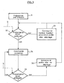
- FIG. 3 a simplified flowchart shows the operation of the unstacking device according to the invention with the sensors and more particularly the operation of the control unit 13.
- the control unit actuates all motorized drives for operation at a constant unstacking rate.
- the speeds of movement of the conveyor belt 2 and the pallet 4 are identical.
- the speed of movement of the belts of the conveyors 12 is slightly greater than that of the band 2 or the pallet.
- the speed of movement of the belts 9 is much greater than that of the belts of the conveyors 12.
- the speed of the belt 2 is 0.096 m / s
- that of the belts of the conveyors 12 is 0.152 m / s
- that of the perforated strips 9 is 1.5 m / s.
- the stack of shipments 3 singing then advances towards the unstacking head 5 and the first mailings to the front of the stack fall into the chute 11.
- the stack of shipments is split and the shipments on edge in the fall are placed in fan under the action of the faster movement of the conveyors 12 in the bottom of the fall and a first current to be unstacked is detected for example by the sensor 23.
- step 32 the process continues at step 32 where the signals S provided by the sensors are controlled by the control unit 13 to determine whether the current mail item to be unstacked has a proper presentation with respect to the unstacking head to be stripped without risk of damage or jam.
- step 33 the control unit 13 maintains in normal depilatory operation the belt conveyor 2, the pallet 4, the conveyors 12 and actuates the motorized drive perforated strips 9 and suction nozzles so as to depilate the shipment.
- the current sending is then serialized by passing between the deformable wheels 10, the motorized drive of the perforated strips 9 and the suction nozzles is stopped and the process loops on the step 32 for a new control of the S signals. loop process, shipments are unstacked at a constant rate of one mailing every 330 milliseconds.
- step 32 the signals S provided by the sensors are indicative of an inadequate presentation of the current mail with respect to the unstacking head 5
- the process continues in step 34 where the control unit 13 triggers a correction phase of the presentation of the current shipment relative to the unstacking head.
- the training motorized perforated strips 9 and suction nozzles being stopped the current shipment is not depilated.
- control unit 13 independently controls the motorized drives of the conveyor 2, the pallet 4 and the conveyors 12 of the chute so as to straighten the postal items which are in the chute 11 and thus correct the presentation of the current item to be unstacked.
- step 34 the unit 13 checks, in step 35, the signals S supplied by the sensors to the control unit 13 to determine whether the current mail is now adequate compared to the unstacking head.
- steps 34 and 35 can be performed almost simultaneously.
- step 35 the signals S of the sensors are indicative of an adequate presentation of the current item to be unstacked and that one is in the time window T compatible with a constant pitch between consecutive items at the output of the unstacking device, then the control unit 13 continues the process in step 36 by operating the motorized drive of the unstacking head (perforated strips and suction nozzles).
- the current to be despatched is then serialized between the deformable wheels 10 at the output of the unstacking device, the motorized drive of the perforated strips 9 and the suction nozzles is stopped and the normal unstacking operation is restored. The process then loops to step 32.
- step 35 if the signals S of the sensors are indicative of an inadequate presentation of the current mail item to be unstacked and / or that is outside the time window T, the process loops to the step 34 to continue the correction phase or adapt the correction according to the signals S.
- steps 34 and 35 are repeated as many times as necessary until a proper presentation of the current mail item to be popped up in the time window T is made, but it is preferable that beyond a certain period of time correction without obtaining an adequate presentation, an alarm is triggered to prevent the need for manual intervention.
- an inadequate presentation of the current item to be unstacked with respect to the unstacking head 5 is detected on the basis of a control of the signals supplied by the four sensors 20, 21, 22 and 23.
- a Proper presentation of the current mail item to be unstacked is detected on the basis of a control of the signals provided by the same sensors 20, 21, 22 and 23.
- the criteria for judging whether or not the current item to be unstuffed with respect to the unstacking head can be codified in a truth table as illustrated on the figure 12 .
- this truth table has been illustrated with on the left a very schematic representation of the current mail item to be displayed in profile in correspondence with the value of the signal supplied by the sensors 20 to 24.
- a signal with the value of "1” indicates a detection of the presence of a shipment while a signal at the value of "0" indicates the absence of detection of the presence of a shipment.
- the drives of the motorized drives of the belt conveyor 2, the pallet 4 and the secondary conveyors 12 are also shown as a function of the signals supplied by the sensors 20 to 24.
- the control unit 13 can react by actuating the motorized drive of the unstacking head only if the current mail is not already engaged in the entry cone between the deformable wheels 10 (detected by the sensors 26 and 27).
- the control unit 13 can also, on detection of collapsed shipments in the chute, do not actuate the motorized drive of the unstacking head during the time window T, the time to straighten these shipments by pushing them with shipments on the main conveyor. If the control unit 13 detects by the sensors that only the foot of the current item is poorly presented, it may not operate the motorized drive of the unstacking head during the time window T so that the conveyors 12 in the fall have time to restore the presentation of this current shipment.
- step 34 of the figure 3 The process of recovery of shipments in step 34 of the figure 3 will be better understood in the light of the presentation of different example cases below.
- This situation is detected by the control unit 13 because the sensor 22 produces a signal indicative of the absence of sending while the sensors 20, 21 and 23 each produce a signal indicative of the presence of a shipment. This situation corresponds to the third line of the truth table of the figure 12 .
- control unit 13 detects an unsuitable presentation of the current item to be unstacked and orders at step 34 a correction phase of the presentation of the current item. relative to the unstacking head.
- step 34 the control unit 13 controls the motorized drives of the conveyor 2 and the pallet 4 by passing them at a low speed of displacement at 0.096 m / s. At the same time, the control unit 13 suspends the motorized drive of the belt conveyors 12, since as indicated by the sensors 20 and 21 the foot of the current mailpiece is correctly pressed against the head 5, which has the effect of to straighten shipments in the fall because new shipments arrive from the main conveyor 2 pushed by pallet 4.
- the unit 13 controls, in step 35, the signals of the sensors.
- step 35 if the signals S of the sensors are indicative of an adequate presentation of the current item to be unstacked and which is in the time window T, the control unit 13 continues the process to step 36 by operating the motorized drive of the unstacking head (perforated strips and suction nozzles).
- the current to be despatched is then serialized between the deformable wheels 10 at the output of the unstacking device, the motorized drive of the perforated strips 9 and the suction nozzles is stopped and the normal unstacking operation is restored. The process then loops to step 32.
- step 35 if the signals S of the sensors are indicative of an unsuitable presentation of the current item to be unstacked, the process loops in step 34 to continue the correction phase or to adapt the correction to function of the signals S.
- the unit control 13 controls the belt conveyors 12 to pass in average speed to 0.152 m / s so as to straighten the shipments in the fall 11. This situation corresponds to the second line of the truth table of the figure 12 .
- Another similar situation would occur with sensors 20, 21 and 22 which each provide a signal indicative of the absence of a sending while the sensors 23 and 24 each provide a signal indicative of the presence of a shipment.
- This situation corresponds to inclined consignments in the left-hand part of the fall on the figure 5 .
- the control unit 13 in step 34 controls the belt conveyors 12 to pass them at an average speed of 0.152 m / s and controls the motorized drives of the conveyor 2 and the pallet 4 by passing them in small movement speed at 0.096 m / s.
- This situation corresponds to the fourth line of the truth table of the figure 12 .
- a particular situation would arise with sensors 21 and 22 which each provide a signal indicative of the absence of a sending while the sensors 20, 23 and 24 each provide a signal indicative of the presence of a shipment.
- the control unit 13 in step 34 controls the belt conveyors 12 to pass them in medium speed in reverse at 0.152 m / s and controls the motorized drives of the conveyor 2 and the pallet 4 in them. moving in low speed of displacement to 0.096 m / s.
- This situation corresponds to the fifth line of the truth table of the figure 12 .
- the sensor 24 detects the presence of a shipment.
- the control unit 13 thus detects an inadequate presentation of the current mail with respect to the unstacking head 5.
- the control unit 13 starts a correction phase consisting of simultaneously to interrupt the drive of the conveyor 2 for 25 milliseconds, change the speed of movement of the pallet in low speed to 0.096 m / s and interrupt the drive of the conveyors 12 of the chute. After the delay of 25 milliseconds, the unit 13 changes the speed of the belt conveyor 2 to 0.096 m / s.
- This correction phase causes a shift between the pallet 2 and the conveyor 2 at the top of the shipments both on the main conveyor 2 and in the chute 11.
- the unit 13 checks, in step 35, whether the signals S of the sensors are indicative of an adequate presentation of the current item and that one is in the time window T. In this case, at step 36, the control unit 13 actuates the motorized drive of the unstacking head and continues the process as previously described.
- step 35 if the signals S of the sensors are indicative of an inadequate presentation of the current send, the process loops in step 34 to continue the correction phase or to adapt the correction as a function of the signals. S.
- FIG 7 another example of an inadequate presentation of the current item to be unstacked with respect to the unstacking head has been illustrated.
- the top of the shipments in the chute collapses backwards and at the same time the foot of the shipments in the fall collapses towards the rear.
- the sensors 20 and 23 each provide a signal indicative of the absence of a sending while the sensors 21, 22 and 24 each provide a signal indicative of the presence of a shipment.
- This situation corresponds to the sixth line of the truth table of the figure 12 .
- step 34 the control unit 13 triggers a correction phase of suspending the drive of the belt conveyor 2 for 25 milliseconds and then changes the speed of the conveyor 2 to 0.096 m / s.
- the speed of movement of the pallet 4 has changed to a low speed mode at 0.096 m / s while the speed of the conveyors 12 has increased to an average speed of 0.152 m / s. This has the effect on the one hand to straighten the top of the shipments in the fall and at the same time to advance the foot of the shipments to the unstacking head.
- the unit 13 checks, in step 35, whether the signals S of the sensors are indicative of an adequate presentation of the current item and that one is in the time window T and the process continues as described previously.
- FIG 8 another example of an inadequate presentation of the current item to be unstacked with respect to the unstacking head has been illustrated.
- the feet of the items in the chute are set back relative to the unstacking head.
- the sensors 20 and 21 each provide a signal indicative of the absence of a sending while the sensors 22 and 23 each provide a signal indicative of the presence of a shipment.
- the sensor 24 also provides a signal indicative of the absence of sending in the chute. In this case the fall is insufficiently fed with shipments.
- This situation corresponds to the ninth line of the truth table of the figure 12 .
- step 34 the control unit 13 triggers a correction phase consisting of moving the conveyor 2 and the pallet 4 at a low speed of 0.096 m / s while the conveyors 12 are changed to an average speed of 0.152 m / s. s
- the sensors 21 and 24 each provide a signal indicative of the absence of a sending while the sensors 20, 22 and 23 each provide a signal indicative of the presence of a shipment. This situation corresponds to the tenth line of the truth table of the figure 12 .
- step 34 the control unit 13 passes the pallet 4 and the conveyor 2 of the main magazine in low speed at 0.096 m / s while it controls a reverse of the conveyors 12 at an average speed of 0.152 m / s.
- the sensors 20, 21 provide a signal indicative of the absence of a sending while the sensors 22, 23 and 24 each provide a signal indicative of the presence of a shipment.
- This situation corresponds to the eleventh line of the truth table of the figure 12 .
- step 34 the control unit 13 passes the conveyor 2 and the pallet 4 in low speed at 0.096 m / s for 25 milliseconds and then interrupts their operation. At the same time, it passes conveyors 12 at an average speed of 0.152 m / s to straighten shipments in the fall without fueling the drop in shipments.
- the presentation of the items is similar to the situation of the figure 10 but the foot of the shipments collapses on the front.
- the sensor 21 provides a signal indicative of the absence of a sending while the sensors 20, 22, 23 and 24 each provide a signal indicative of the presence of a shipment. This situation corresponds to the twelfth line of the truth table of the figure 12 .
- control unit 13 passes the conveyor 2 and the pallet 4 at low speed for 25 milliseconds and then interrupts their operation. At the same time, it passes the conveyors 12 in reverse at a speed of 0.152 m / s to straighten the shipments in the fall.
- the invention is not limited to the sole embodiment of the unstacking device described above. In particular, one would not depart from the scope of the invention by modifying the detail of the sensors, by modifying the number of sensors, by applying different corrections in response to the signals provided by the sensors.
Landscapes
- Engineering & Computer Science (AREA)
- Mechanical Engineering (AREA)
- Sorting Of Articles (AREA)
- Sheets, Magazines, And Separation Thereof (AREA)
- Devices For Checking Fares Or Tickets At Control Points (AREA)
- Delivering By Means Of Belts And Rollers (AREA)
- Controlling Sheets Or Webs (AREA)
- Management, Administration, Business Operations System, And Electronic Commerce (AREA)
- Character Discrimination (AREA)
- Information Transfer Between Computers (AREA)
Claims (10)
- Vorrichtung zur Entstapelung von flachen Objekten, die ein motorisiertes, gesteuertes Vorratsmagazin umfasst, um flache Objekte auf ihrem Rand in einem Stapel gegenüber einem Entstapelungskopf (5) mit einem motorisierten Lochbandantrieb und mit einer Unterdruckkammer zu verschieben, der betätigt wird, um ein erstes, aktuelles Objekt vom Stapel zu trennen und es in eine zu der Richtung der Bewegung des Stapels flacher Objekte transversale Richtung zu bewegen, in der der motorisierte Antrieb für jede Entstapelung eines aktuellen Objektes betrieben und angehalten wird, und der Stapel flacher Objekte in dem Magazin infolge einer Feststellung von Signalen, geliefert durch eine Vielzahl von im Entstapelungskopf angebrachten Sensoren, ausgerichtet wird, wobei ein erster Sensor (20) angeordnet ist, um die Anwesenheit eines unteren Bereichs des aktuellen Objekts gegenüber dem Entstapelungskopf (5) festzustellen, ein zweiter Sensor (21) angeordnet ist, um die Anwesenheit eines ersten mittleren Bereichs des aktuellen Objekts gegenüber dem Entstapelungskopf (5) festzustellen, wobei der erste mittlere Bereich über dem unteren Bereich des aktuellen Objekts liegt, dadurch gekennzeichnet, dass ein dritter Sensor (22) angeordnet ist, um die Anwesenheit eines zweiten mittleren Bereichs des aktuellen Objekts gegenüber dem Entstapelungskopf festzustellen, wobei dieser zweite mittlere Bereich über dem ersten mittleren Bereich des aktuellen Objekts liegt, die Sensoren (20, 21, 22) im Entstapelungskopf so angebracht sind, dass sie Signale zur Anzeige einer geeigneten Bereitstellung des aktuellen Objekts gegenüber dem Entstapelungskopf (5) liefern, und dadurch, dass der Antrieb des Entstapelungskopfs betätigbar ist, wenn die Signale eine geeignete Bereitstellung des aktuellen Objekts anzeigen.
- Vorrichtung zur Entstapelung gemäß Anspruch 1, in welchem der Entstapelungskopf (5) ein mit zwei Öffnungen nebeneinander ausgestattetes Blech umfasst.
- Vorrichtung zur Entstapelung gemäß einem der Ansprüche 1 oder 2, in welchem der erste Sensor (20) ein mechanischer Aufnehmer ist, der zweite Sensor (21) ein optischer Reflexionsaufnehmer ist und der dritte Sensor (22) ein optischer Reflexionsaufnehmer ist.
- Vorrichtung zur Entstapelung gemäß einem der Ansprüche 2 oder 3, in welchem der erste, zweite und dritte Sensor (20, 21, 22) vertikal im Entstapelungskopf zwischen den zwei Öffnungen übereinander angeordnet sind.
- Vorrichtung zur Entstapelung gemäß einem der vorhergehenden Ansprüche, in welchem die Vielzahl von Sensoren außerdem einen vierten Sensor (23) umfasst, der angeordnet ist, um die Anwesenheit eines flachen Objekts gemäß der zu der Richtung der Bewegung des Stapels flacher Objekte transversalen Richtung festzustellen.
- Vorrichtung zur Entstapelung gemäß Anspruch 5, in welchem der vierte Sensor (23) ein optischer Sperrsensor ist.
- Vorrichtung zur Entstapelung gemäß einem der vorhergehenden Ansprüche, in welchem das Vorratsmagazin eine Rutsche (11) umfasst, die zwischen einem Hauptförderer (2) mit einem motorisieren Antrieb und dem Entstapelungskopf (5) sowie einer Palette (4) mit einem motorisierten Antrieb angebracht ist, wobei die Palette geeignet ist, entlang der Länge des Hauptförderers verschoben zu werden, die Rutsche mit Sekundärförderern mit einem motorisierten Antrieb (12) ausgestattet ist, und die Steuerungseinheit auf die motorisierten Antriebe des Hauptförderers, der Palette und der Sekundärförderer einwirkt, um in geeigneter Weise das aktuelle Objekt gegenüber dem Entstapelungskopf bereitzustellen.
- Vorrichtung zur Entstapelung gemäß Anspruch 7, in welcher die Steuerungseinheit (13) so eingerichtet ist, dass durch Änderung von Geschwindigkeit und Richtung der motorisierten Antriebe des Vorratsmagazins das aktuelle Objekt in geeigneter Weise gegenüber dem Entstapelungskopf (5) bereitgestellt wird.
- Vorrichtung zur Entstapelung gemäß Anspruch 8, in welcher die Steuerungseinheit (13) so eingerichtet ist, dass ein Alarm nach einer gewissen Zeitdauer ausgelöst wird, während der die Steuerungseinheit (13) auf die motorisierten Antriebe von Hauptförderer, Palette und Sekundärförderer einwirkt, ohne eine geeignete Bereitstellung des aktuellen Objektes gegenüber dem Entstapelungskopf zu erhalten.
- Maschine zur Behandlung von Postsendungen, dadurch gekennzeichnet, dass sie eine Vorrichtung zur Entstapelung gemäß einem der vorhergehenden Ansprüche umfasst.
Applications Claiming Priority (1)
| Application Number | Priority Date | Filing Date | Title |
|---|---|---|---|
| FR0653854A FR2906235B1 (fr) | 2006-09-21 | 2006-09-21 | Dispositif de depilage d'envois postaux avec une gestion optimisee des conditions de depilage |
Publications (2)
| Publication Number | Publication Date |
|---|---|
| EP1902989A1 EP1902989A1 (de) | 2008-03-26 |
| EP1902989B1 true EP1902989B1 (de) | 2009-06-17 |
Family
ID=37944304
Family Applications (1)
| Application Number | Title | Priority Date | Filing Date |
|---|---|---|---|
| EP07116139A Not-in-force EP1902989B1 (de) | 2006-09-21 | 2007-09-11 | Vorrichtung zum Entstapeln von Postsendungen mit optimierter Verwaltung der Entstapelbedingungen |
Country Status (7)
| Country | Link |
|---|---|
| US (1) | US7712735B2 (de) |
| EP (1) | EP1902989B1 (de) |
| AT (1) | ATE433939T1 (de) |
| DE (1) | DE602007001320D1 (de) |
| ES (1) | ES2327790T3 (de) |
| FR (1) | FR2906235B1 (de) |
| PT (1) | PT1902989E (de) |
Families Citing this family (11)
| Publication number | Priority date | Publication date | Assignee | Title |
|---|---|---|---|---|
| JP2008273666A (ja) * | 2007-04-26 | 2008-11-13 | Toshiba Corp | 紙葉類取り出し装置 |
| US9044783B2 (en) | 2013-03-12 | 2015-06-02 | The United States Postal Service | System and method of unloading a container of items |
| US9376275B2 (en) * | 2013-03-12 | 2016-06-28 | United States Postal Service | Article feeder with a retractable product guide |
| US9340377B2 (en) | 2013-03-12 | 2016-05-17 | United States Postal Service | System and method of automatic feeder stack management |
| US9061849B2 (en) | 2013-03-14 | 2015-06-23 | United States Postal Service | System and method of article feeder operation |
| US9056738B2 (en) | 2013-03-13 | 2015-06-16 | United States Postal Service | Anti-rotation device and method of use |
| JP6017355B2 (ja) * | 2013-03-21 | 2016-10-26 | 株式会社東芝 | 紙葉類の取出し装置 |
| FR3037261B1 (fr) * | 2015-06-11 | 2021-02-26 | Solystic | Dispositif de depilage avec systeme de vision |
| CN107298336A (zh) * | 2017-06-09 | 2017-10-27 | 安徽天斯努信息技术股份有限公司 | 一种便于打印装订的打印机出纸架 |
| US10065826B1 (en) * | 2017-08-04 | 2018-09-04 | Xerox Corporation | Stacking module with fans |
| JP2020093879A (ja) | 2018-12-11 | 2020-06-18 | キヤノン株式会社 | シート検知装置及び画像形成装置 |
Family Cites Families (14)
| Publication number | Priority date | Publication date | Assignee | Title |
|---|---|---|---|---|
| GB1217578A (en) * | 1968-03-22 | 1970-12-31 | Int Computers Ltd | Improvements in or relating to document feeding apparatus |
| US4934682A (en) * | 1989-03-13 | 1990-06-19 | R. A. Jones & Co. Inc. | Apparatus for feeding cartons |
| WO1991015416A1 (en) * | 1990-04-07 | 1991-10-17 | David Sarnoff Research Center, Inc. | Flats mail singulation apparatus |
| IT1256935B (it) * | 1992-08-10 | 1995-12-27 | Vincenzo Priolo | Dispositivo di smistamento singolo per oggetti postali. |
| US5299797A (en) * | 1992-08-28 | 1994-04-05 | Bell & Howell Phillipsburg Company | Segmented document transport section having accelerated take-away belts |
| DE19547292A1 (de) * | 1995-12-19 | 1997-06-26 | Aeg Electrocom Gmbh | Vorrichtung und Verfahren zum Zwischenstapeln von Sendungen |
| US6003857A (en) * | 1997-10-03 | 1999-12-21 | Pitney Bowes Inc. | Singulating apparatus for a mail handling system |
| US6467764B1 (en) * | 1999-09-24 | 2002-10-22 | Kenneth A. Stevens | High capacity document sheet processor |
| US6511062B1 (en) * | 2000-02-07 | 2003-01-28 | Lockheed Martin Corporation | Presentation control for flat article singulation mechanism and sensors suitable for use therewith |
| JP4044281B2 (ja) * | 2000-12-21 | 2008-02-06 | 日立オムロンターミナルソリューションズ株式会社 | 紙幣取扱装置 |
| US7195236B2 (en) * | 2003-03-28 | 2007-03-27 | Northrop Grumman Corporation | Automated induction systems and methods for mail and/or other objects |
| DE10350623B3 (de) * | 2003-10-30 | 2005-04-14 | Siemens Ag | Vorrichtung zum Vereinzeln von flachen Sendungen in stehender Position aus einem Sendungsstapel |
| EP1794073B1 (de) * | 2004-09-24 | 2014-03-05 | Northrop Grumman Systems Corporation | Kippschutzvorrichtung für post und/oder ähnliches |
| US7404554B2 (en) * | 2005-02-22 | 2008-07-29 | Graphic Packaging International, Inc. | Method and apparatus for magazine pressure control |
-
2006
- 2006-09-21 FR FR0653854A patent/FR2906235B1/fr not_active Expired - Fee Related
-
2007
- 2007-09-11 EP EP07116139A patent/EP1902989B1/de not_active Not-in-force
- 2007-09-11 DE DE602007001320T patent/DE602007001320D1/de active Active
- 2007-09-11 PT PT07116139T patent/PT1902989E/pt unknown
- 2007-09-11 ES ES07116139T patent/ES2327790T3/es active Active
- 2007-09-11 AT AT07116139T patent/ATE433939T1/de not_active IP Right Cessation
- 2007-09-20 US US11/858,468 patent/US7712735B2/en not_active Expired - Fee Related
Also Published As
| Publication number | Publication date |
|---|---|
| FR2906235B1 (fr) | 2009-05-29 |
| US7712735B2 (en) | 2010-05-11 |
| ES2327790T3 (es) | 2009-11-03 |
| ATE433939T1 (de) | 2009-07-15 |
| US20080073827A1 (en) | 2008-03-27 |
| DE602007001320D1 (de) | 2009-07-30 |
| PT1902989E (pt) | 2009-07-31 |
| EP1902989A1 (de) | 2008-03-26 |
| FR2906235A1 (fr) | 2008-03-28 |
Similar Documents
| Publication | Publication Date | Title |
|---|---|---|
| EP1902989B1 (de) | Vorrichtung zum Entstapeln von Postsendungen mit optimierter Verwaltung der Entstapelbedingungen | |
| EP2222586B1 (de) | Vorrichtung zur entstapelung multimodaler postsendungen | |
| EP0562954B1 (de) | Vorrichtung zum Zuführen von flachen, hochkantgestellten Gegenständen an den Entstapelkopf eines automatischen Sortiersystems | |
| EP2552813B1 (de) | Vorrichtung zum trennen flacher objekte, steuerungsverfahren dafür und postsortiermaschine | |
| EP2605867B1 (de) | Postsortiermaschine mit klemmförderung und verfahren zum betrieb derselbigen | |
| EP2049423B1 (de) | Entstapelungsvorrichtung mit einem einziehbaren blaselement | |
| EP1923340B1 (de) | Vorrichtung zum automatischen Laden von Umschlägen | |
| US4257531A (en) | Delivery apparatus for automatic newspaper vending machine | |
| EP2042459B1 (de) | Stapelvorrichtungen für Postsendungen | |
| EP2172909B1 (de) | Vorrichtung zur Digitalisierung für Frankiersystem | |
| EP2172908B1 (de) | Vorrichtung zur Digitalisierung für Frankiersystem | |
| EP2031565B1 (de) | Vorrichtung für die Zuführung von Postartikeln mit integriertem Bildsensor | |
| EP3307659B1 (de) | Entstapelungsvorrichtung mit betrachtungssystem | |
| EP3986815B1 (de) | Versorgungsvorrichtung zur versorgung eines postsortierförderers mit postsendungen | |
| WO2009024693A1 (fr) | Dispositif de convoyage d'envois avec un asservissement sur le taux de rejet | |
| EP2305584A1 (de) | Zuführvorrichtung mit kontrollierter Umschlagtrennung |
Legal Events
| Date | Code | Title | Description |
|---|---|---|---|
| PUAI | Public reference made under article 153(3) epc to a published international application that has entered the european phase |
Free format text: ORIGINAL CODE: 0009012 |
|
| AK | Designated contracting states |
Kind code of ref document: A1 Designated state(s): AT BE BG CH CY CZ DE DK EE ES FI FR GB GR HU IE IS IT LI LT LU LV MC MT NL PL PT RO SE SI SK TR |
|
| AX | Request for extension of the european patent |
Extension state: AL BA HR MK YU |
|
| 17P | Request for examination filed |
Effective date: 20080926 |
|
| AKX | Designation fees paid |
Designated state(s): AT BE BG CH CY CZ DE DK EE ES FI FR GB GR HU IE IS IT LI LT LU LV MC MT NL PL PT RO SE SI SK TR |
|
| GRAP | Despatch of communication of intention to grant a patent |
Free format text: ORIGINAL CODE: EPIDOSNIGR1 |
|
| GRAS | Grant fee paid |
Free format text: ORIGINAL CODE: EPIDOSNIGR3 |
|
| GRAA | (expected) grant |
Free format text: ORIGINAL CODE: 0009210 |
|
| AK | Designated contracting states |
Kind code of ref document: B1 Designated state(s): AT BE BG CH CY CZ DE DK EE ES FI FR GB GR HU IE IS IT LI LT LU LV MC MT NL PL PT RO SE SI SK TR |
|
| REG | Reference to a national code |
Ref country code: GB Ref legal event code: FG4D Free format text: NOT ENGLISH |
|
| REG | Reference to a national code |
Ref country code: CH Ref legal event code: EP |
|
| REG | Reference to a national code |
Ref country code: IE Ref legal event code: FG4D Free format text: LANGUAGE OF EP DOCUMENT: FRENCH |
|
| REF | Corresponds to: |
Ref document number: 602007001320 Country of ref document: DE Date of ref document: 20090730 Kind code of ref document: P |
|
| REG | Reference to a national code |
Ref country code: PT Ref legal event code: SC4A Free format text: AVAILABILITY OF NATIONAL TRANSLATION Effective date: 20090724 |
|
| REG | Reference to a national code |
Ref country code: SE Ref legal event code: TRGR |
|
| PG25 | Lapsed in a contracting state [announced via postgrant information from national office to epo] |
Ref country code: LT Free format text: LAPSE BECAUSE OF FAILURE TO SUBMIT A TRANSLATION OF THE DESCRIPTION OR TO PAY THE FEE WITHIN THE PRESCRIBED TIME-LIMIT Effective date: 20090617 Ref country code: AT Free format text: LAPSE BECAUSE OF FAILURE TO SUBMIT A TRANSLATION OF THE DESCRIPTION OR TO PAY THE FEE WITHIN THE PRESCRIBED TIME-LIMIT Effective date: 20090617 |
|
| REG | Reference to a national code |
Ref country code: ES Ref legal event code: FG2A Ref document number: 2327790 Country of ref document: ES Kind code of ref document: T3 |
|
| PG25 | Lapsed in a contracting state [announced via postgrant information from national office to epo] |
Ref country code: PL Free format text: LAPSE BECAUSE OF FAILURE TO SUBMIT A TRANSLATION OF THE DESCRIPTION OR TO PAY THE FEE WITHIN THE PRESCRIBED TIME-LIMIT Effective date: 20090617 Ref country code: LV Free format text: LAPSE BECAUSE OF FAILURE TO SUBMIT A TRANSLATION OF THE DESCRIPTION OR TO PAY THE FEE WITHIN THE PRESCRIBED TIME-LIMIT Effective date: 20090617 Ref country code: SI Free format text: LAPSE BECAUSE OF FAILURE TO SUBMIT A TRANSLATION OF THE DESCRIPTION OR TO PAY THE FEE WITHIN THE PRESCRIBED TIME-LIMIT Effective date: 20090617 |
|
| REG | Reference to a national code |
Ref country code: IE Ref legal event code: FD4D |
|
| PG25 | Lapsed in a contracting state [announced via postgrant information from national office to epo] |
Ref country code: RO Free format text: LAPSE BECAUSE OF FAILURE TO SUBMIT A TRANSLATION OF THE DESCRIPTION OR TO PAY THE FEE WITHIN THE PRESCRIBED TIME-LIMIT Effective date: 20090617 Ref country code: CZ Free format text: LAPSE BECAUSE OF FAILURE TO SUBMIT A TRANSLATION OF THE DESCRIPTION OR TO PAY THE FEE WITHIN THE PRESCRIBED TIME-LIMIT Effective date: 20090617 Ref country code: IS Free format text: LAPSE BECAUSE OF FAILURE TO SUBMIT A TRANSLATION OF THE DESCRIPTION OR TO PAY THE FEE WITHIN THE PRESCRIBED TIME-LIMIT Effective date: 20091017 Ref country code: IE Free format text: LAPSE BECAUSE OF FAILURE TO SUBMIT A TRANSLATION OF THE DESCRIPTION OR TO PAY THE FEE WITHIN THE PRESCRIBED TIME-LIMIT Effective date: 20090617 Ref country code: EE Free format text: LAPSE BECAUSE OF FAILURE TO SUBMIT A TRANSLATION OF THE DESCRIPTION OR TO PAY THE FEE WITHIN THE PRESCRIBED TIME-LIMIT Effective date: 20090617 |
|
| PG25 | Lapsed in a contracting state [announced via postgrant information from national office to epo] |
Ref country code: SK Free format text: LAPSE BECAUSE OF FAILURE TO SUBMIT A TRANSLATION OF THE DESCRIPTION OR TO PAY THE FEE WITHIN THE PRESCRIBED TIME-LIMIT Effective date: 20090617 |
|
| PG25 | Lapsed in a contracting state [announced via postgrant information from national office to epo] |
Ref country code: BG Free format text: LAPSE BECAUSE OF FAILURE TO SUBMIT A TRANSLATION OF THE DESCRIPTION OR TO PAY THE FEE WITHIN THE PRESCRIBED TIME-LIMIT Effective date: 20090917 |
|
| PLBE | No opposition filed within time limit |
Free format text: ORIGINAL CODE: 0009261 |
|
| STAA | Information on the status of an ep patent application or granted ep patent |
Free format text: STATUS: NO OPPOSITION FILED WITHIN TIME LIMIT |
|
| PG25 | Lapsed in a contracting state [announced via postgrant information from national office to epo] |
Ref country code: MC Free format text: LAPSE BECAUSE OF NON-PAYMENT OF DUE FEES Effective date: 20090930 Ref country code: DK Free format text: LAPSE BECAUSE OF FAILURE TO SUBMIT A TRANSLATION OF THE DESCRIPTION OR TO PAY THE FEE WITHIN THE PRESCRIBED TIME-LIMIT Effective date: 20090617 |
|
| 26N | No opposition filed |
Effective date: 20100318 |
|
| PG25 | Lapsed in a contracting state [announced via postgrant information from national office to epo] |
Ref country code: GR Free format text: LAPSE BECAUSE OF FAILURE TO SUBMIT A TRANSLATION OF THE DESCRIPTION OR TO PAY THE FEE WITHIN THE PRESCRIBED TIME-LIMIT Effective date: 20090918 |
|
| PG25 | Lapsed in a contracting state [announced via postgrant information from national office to epo] |
Ref country code: IT Free format text: LAPSE BECAUSE OF FAILURE TO SUBMIT A TRANSLATION OF THE DESCRIPTION OR TO PAY THE FEE WITHIN THE PRESCRIBED TIME-LIMIT Effective date: 20090617 |
|
| PG25 | Lapsed in a contracting state [announced via postgrant information from national office to epo] |
Ref country code: MT Free format text: LAPSE BECAUSE OF FAILURE TO SUBMIT A TRANSLATION OF THE DESCRIPTION OR TO PAY THE FEE WITHIN THE PRESCRIBED TIME-LIMIT Effective date: 20090617 Ref country code: LU Free format text: LAPSE BECAUSE OF NON-PAYMENT OF DUE FEES Effective date: 20090911 |
|
| PG25 | Lapsed in a contracting state [announced via postgrant information from national office to epo] |
Ref country code: HU Free format text: LAPSE BECAUSE OF FAILURE TO SUBMIT A TRANSLATION OF THE DESCRIPTION OR TO PAY THE FEE WITHIN THE PRESCRIBED TIME-LIMIT Effective date: 20091218 |
|
| PG25 | Lapsed in a contracting state [announced via postgrant information from national office to epo] |
Ref country code: TR Free format text: LAPSE BECAUSE OF FAILURE TO SUBMIT A TRANSLATION OF THE DESCRIPTION OR TO PAY THE FEE WITHIN THE PRESCRIBED TIME-LIMIT Effective date: 20090617 |
|
| PG25 | Lapsed in a contracting state [announced via postgrant information from national office to epo] |
Ref country code: CY Free format text: LAPSE BECAUSE OF FAILURE TO SUBMIT A TRANSLATION OF THE DESCRIPTION OR TO PAY THE FEE WITHIN THE PRESCRIBED TIME-LIMIT Effective date: 20090617 |
|
| REG | Reference to a national code |
Ref country code: CH Ref legal event code: PL |
|
| PG25 | Lapsed in a contracting state [announced via postgrant information from national office to epo] |
Ref country code: LI Free format text: LAPSE BECAUSE OF NON-PAYMENT OF DUE FEES Effective date: 20110930 Ref country code: CH Free format text: LAPSE BECAUSE OF NON-PAYMENT OF DUE FEES Effective date: 20110930 |
|
| REG | Reference to a national code |
Ref country code: FR Ref legal event code: PLFP Year of fee payment: 10 |
|
| REG | Reference to a national code |
Ref country code: FR Ref legal event code: PLFP Year of fee payment: 11 |
|
| REG | Reference to a national code |
Ref country code: FR Ref legal event code: PLFP Year of fee payment: 12 |
|
| PGFP | Annual fee paid to national office [announced via postgrant information from national office to epo] |
Ref country code: PT Payment date: 20200908 Year of fee payment: 14 Ref country code: FR Payment date: 20200918 Year of fee payment: 14 Ref country code: GB Payment date: 20200922 Year of fee payment: 14 Ref country code: NL Payment date: 20200925 Year of fee payment: 14 Ref country code: DE Payment date: 20200925 Year of fee payment: 14 Ref country code: FI Payment date: 20200921 Year of fee payment: 14 |
|
| PGFP | Annual fee paid to national office [announced via postgrant information from national office to epo] |
Ref country code: SE Payment date: 20200925 Year of fee payment: 14 Ref country code: BE Payment date: 20200925 Year of fee payment: 14 |
|
| PGFP | Annual fee paid to national office [announced via postgrant information from national office to epo] |
Ref country code: ES Payment date: 20201120 Year of fee payment: 14 |
|
| REG | Reference to a national code |
Ref country code: DE Ref legal event code: R119 Ref document number: 602007001320 Country of ref document: DE |
|
| REG | Reference to a national code |
Ref country code: FI Ref legal event code: MAE |
|
| PG25 | Lapsed in a contracting state [announced via postgrant information from national office to epo] |
Ref country code: FI Free format text: LAPSE BECAUSE OF NON-PAYMENT OF DUE FEES Effective date: 20210911 |
|
| REG | Reference to a national code |
Ref country code: SE Ref legal event code: EUG |
|
| REG | Reference to a national code |
Ref country code: NL Ref legal event code: MM Effective date: 20211001 |
|
| REG | Reference to a national code |
Ref country code: BE Ref legal event code: MM Effective date: 20210930 |
|
| GBPC | Gb: european patent ceased through non-payment of renewal fee |
Effective date: 20210911 |
|
| PG25 | Lapsed in a contracting state [announced via postgrant information from national office to epo] |
Ref country code: PT Free format text: LAPSE BECAUSE OF NON-PAYMENT OF DUE FEES Effective date: 20220311 |
|
| PG25 | Lapsed in a contracting state [announced via postgrant information from national office to epo] |
Ref country code: NL Free format text: LAPSE BECAUSE OF NON-PAYMENT OF DUE FEES Effective date: 20211001 |
|
| PG25 | Lapsed in a contracting state [announced via postgrant information from national office to epo] |
Ref country code: SE Free format text: LAPSE BECAUSE OF NON-PAYMENT OF DUE FEES Effective date: 20210912 Ref country code: GB Free format text: LAPSE BECAUSE OF NON-PAYMENT OF DUE FEES Effective date: 20210911 Ref country code: FR Free format text: LAPSE BECAUSE OF NON-PAYMENT OF DUE FEES Effective date: 20210930 Ref country code: DE Free format text: LAPSE BECAUSE OF NON-PAYMENT OF DUE FEES Effective date: 20220401 Ref country code: BE Free format text: LAPSE BECAUSE OF NON-PAYMENT OF DUE FEES Effective date: 20210930 |
|
| REG | Reference to a national code |
Ref country code: ES Ref legal event code: FD2A Effective date: 20221028 |
|
| PG25 | Lapsed in a contracting state [announced via postgrant information from national office to epo] |
Ref country code: ES Free format text: LAPSE BECAUSE OF NON-PAYMENT OF DUE FEES Effective date: 20210912 |