EP1903387B1 - Projektionsvorrichtung - Google Patents
Projektionsvorrichtung Download PDFInfo
- Publication number
- EP1903387B1 EP1903387B1 EP06767616A EP06767616A EP1903387B1 EP 1903387 B1 EP1903387 B1 EP 1903387B1 EP 06767616 A EP06767616 A EP 06767616A EP 06767616 A EP06767616 A EP 06767616A EP 1903387 B1 EP1903387 B1 EP 1903387B1
- Authority
- EP
- European Patent Office
- Prior art keywords
- projection
- projector
- cpu
- battery
- control unit
- Prior art date
- Legal status (The legal status is an assumption and is not a legal conclusion. Google has not performed a legal analysis and makes no representation as to the accuracy of the status listed.)
- Not-in-force
Links
- 230000003287 optical effect Effects 0.000 claims abstract description 43
- 230000017525 heat dissipation Effects 0.000 claims description 17
- 239000011810 insulating material Substances 0.000 claims 1
- 239000004973 liquid crystal related substance Substances 0.000 description 39
- 230000015654 memory Effects 0.000 description 21
- 238000004891 communication Methods 0.000 description 15
- 230000007423 decrease Effects 0.000 description 14
- 238000001514 detection method Methods 0.000 description 14
- 230000003247 decreasing effect Effects 0.000 description 10
- 230000015572 biosynthetic process Effects 0.000 description 8
- 239000000463 material Substances 0.000 description 7
- 230000000694 effects Effects 0.000 description 6
- 238000000034 method Methods 0.000 description 6
- 230000006870 function Effects 0.000 description 5
- 230000008859 change Effects 0.000 description 4
- 239000000945 filler Substances 0.000 description 3
- 230000009467 reduction Effects 0.000 description 3
- 235000019504 cigarettes Nutrition 0.000 description 2
- 238000010586 diagram Methods 0.000 description 2
- 230000007246 mechanism Effects 0.000 description 2
- 230000008569 process Effects 0.000 description 2
- 230000008901 benefit Effects 0.000 description 1
- 230000005540 biological transmission Effects 0.000 description 1
- 230000004397 blinking Effects 0.000 description 1
- 238000006243 chemical reaction Methods 0.000 description 1
- 239000003086 colorant Substances 0.000 description 1
- 230000007812 deficiency Effects 0.000 description 1
- 230000001419 dependent effect Effects 0.000 description 1
- 230000005484 gravity Effects 0.000 description 1
- 238000009413 insulation Methods 0.000 description 1
- 230000002250 progressing effect Effects 0.000 description 1
- 230000035807 sensation Effects 0.000 description 1
- 238000004904 shortening Methods 0.000 description 1
- 230000005236 sound signal Effects 0.000 description 1
- 230000003936 working memory Effects 0.000 description 1
Images


Classifications
-
- H—ELECTRICITY
- H04—ELECTRIC COMMUNICATION TECHNIQUE
- H04N—PICTORIAL COMMUNICATION, e.g. TELEVISION
- H04N9/00—Details of colour television systems
- H04N9/12—Picture reproducers
- H04N9/31—Projection devices for colour picture display, e.g. using electronic spatial light modulators [ESLM]
- H04N9/3141—Constructional details thereof
-
- G—PHYSICS
- G03—PHOTOGRAPHY; CINEMATOGRAPHY; ANALOGOUS TECHNIQUES USING WAVES OTHER THAN OPTICAL WAVES; ELECTROGRAPHY; HOLOGRAPHY
- G03B—APPARATUS OR ARRANGEMENTS FOR TAKING PHOTOGRAPHS OR FOR PROJECTING OR VIEWING THEM; APPARATUS OR ARRANGEMENTS EMPLOYING ANALOGOUS TECHNIQUES USING WAVES OTHER THAN OPTICAL WAVES; ACCESSORIES THEREFOR
- G03B21/00—Projectors or projection-type viewers; Accessories therefor
- G03B21/14—Details
- G03B21/142—Adjusting of projection optics
-
- G—PHYSICS
- G03—PHOTOGRAPHY; CINEMATOGRAPHY; ANALOGOUS TECHNIQUES USING WAVES OTHER THAN OPTICAL WAVES; ELECTROGRAPHY; HOLOGRAPHY
- G03B—APPARATUS OR ARRANGEMENTS FOR TAKING PHOTOGRAPHS OR FOR PROJECTING OR VIEWING THEM; APPARATUS OR ARRANGEMENTS EMPLOYING ANALOGOUS TECHNIQUES USING WAVES OTHER THAN OPTICAL WAVES; ACCESSORIES THEREFOR
- G03B21/00—Projectors or projection-type viewers; Accessories therefor
- G03B21/14—Details
- G03B21/145—Housing details, e.g. position adjustments thereof
-
- G—PHYSICS
- G03—PHOTOGRAPHY; CINEMATOGRAPHY; ANALOGOUS TECHNIQUES USING WAVES OTHER THAN OPTICAL WAVES; ELECTROGRAPHY; HOLOGRAPHY
- G03B—APPARATUS OR ARRANGEMENTS FOR TAKING PHOTOGRAPHS OR FOR PROJECTING OR VIEWING THEM; APPARATUS OR ARRANGEMENTS EMPLOYING ANALOGOUS TECHNIQUES USING WAVES OTHER THAN OPTICAL WAVES; ACCESSORIES THEREFOR
- G03B21/00—Projectors or projection-type viewers; Accessories therefor
- G03B21/14—Details
- G03B21/28—Reflectors in projection beam
-
- H—ELECTRICITY
- H04—ELECTRIC COMMUNICATION TECHNIQUE
- H04M—TELEPHONIC COMMUNICATION
- H04M1/00—Substation equipment, e.g. for use by subscribers
- H04M1/02—Constructional features of telephone sets
- H04M1/0202—Portable telephone sets, e.g. cordless phones, mobile phones or bar type handsets
- H04M1/026—Details of the structure or mounting of specific components
- H04M1/0272—Details of the structure or mounting of specific components for a projector or beamer module assembly
-
- H—ELECTRICITY
- H04—ELECTRIC COMMUNICATION TECHNIQUE
- H04M—TELEPHONIC COMMUNICATION
- H04M1/00—Substation equipment, e.g. for use by subscribers
- H04M1/02—Constructional features of telephone sets
- H04M1/0202—Portable telephone sets, e.g. cordless phones, mobile phones or bar type handsets
- H04M1/0206—Portable telephones comprising a plurality of mechanically joined movable body parts, e.g. hinged housings
- H04M1/0208—Portable telephones comprising a plurality of mechanically joined movable body parts, e.g. hinged housings characterized by the relative motions of the body parts
- H04M1/0225—Rotatable telephones, i.e. the body parts pivoting to an open position around an axis perpendicular to the plane they define in closed position
Definitions
- the present invention relates to a projection device that projects an optical image.
- Japanese Patent Publication No. 2000-236375 discloses an electronic device consisting of a portable telephone device or the like equipped with a projection function. With this type of portable telephone device, a person conversing upon the telephone is able to project information upon the palm of his own hand while conversing, and can also project information upon a wall surface while conversing.
- United States Patent Application No. US 2002/0063855 discloses another example of a projection system for a telephone device.
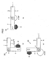
- Figs. 1(a) through 1(c) are views from three sides of a portable battery driven type compact projector according to the first embodiment of the present invention, that can be used while being held in the user's hand.
- Fig. 1 (a) is a left side view
- Fig. 1 (b) is a plan view
- Fig. 1(c) is an elevation view.
- a chassis of a control unit 1 and a chassis of a projector unit 2 are mutually supported by a hinge unit 3 so as to be capable of rotating freely with respect to one another.
- This hinge unit 3 is provided towards one end portion of the projector unit 2 in its longitudinal direction, with the rotation shaft of the hinge unit 3 being orthogonal to the mutually opposing surfaces of the chassis of the control unit 1 and the chassis of the projector unit 2.
- a click mechanism not shown in the figures is provided to the hinge unit 3, and this click mechanism operates so as to set the relative angle ⁇ between the control unit 1 and the projector unit 2 to, for example, a 90° position, a 180° position, or a 270° position.
- this hinge unit 3 may be constructed so as to be capable of mutually supporting the control unit 1 and the projector unit 2 at any desired relative angular click positions, i.e. not only at those specified above.
- a strap fitting member 15 is provided to the control unit 1, to which a strap or the like not shown in the figures may be installed.
- Figs. 2(a) through 2(c) are figures showing one example of three operational modes to which the projector 10 can be set by rotation of the hinge unit 3.
- Fig. 2(a) is a figure showing the projector unit 2 in a state to which it is positioned by rotation of the hinge unit 3 at a relative angle ⁇ of 90°
- Fig. 2(b) is a figure showing the projector unit 2 in a state to which it is positioned by rotation of the hinge unit 3 at a relative angle ⁇ of 180°
- Fig. 2(c) is a figure showing the projector unit 2 in a state to which it is positioned by rotation of the hinge unit 3 at a relative angle ⁇ of 270°.
- Figs. 2(a) is a figure showing the projector unit 2 in a state to which it is positioned by rotation of the hinge unit 3 at a relative angle ⁇ of 270°.
- the ray bundle B is the projected beam generated from the projector unit 2.
- the states of the projector 10 shown in Figs. 2(a) and 2(b) are principally used during hand-held operation. And the state of the projector 10 shown in Fig. 2 (c) is used both during hand-held operation, and also when the projector 10 is set upon a plane support surface.
- the projector 10 When the projector 10 is set upon a plane surface, it may be laid with either an upper surface 1a of the control unit 1 or its lower surface 1b facing downwards. And, when the modes of the projector 10 shown in Figs. 2(a) and 2(b) are being employed, the projector 10 is set with its surface 1a downwards. However, when the mode of the projector 10 shown in Fig. 2 (c) is to be employed, the projector 10 is laid with its surface 1b downwards, so that an operation member 103 can be actuated. Since the size of the control unit 1 is larger than that of the projector unit 2, accordingly the attitude of the projector 10 upon a plane is stable even though the projector unit 2, that is rotated, is not in contact with the supporting plane.
- a lens cover 11, that extends from the surface 1a, is provided to the control unit 1 as shown in Figs. 1(a) through 1(c) .
- this lens cover 11 covers an opening 21 of the projector unit 2, thus protecting a projection lens that is internal to the projector unit 2.
- the lens cover 11 is made as a transparent member, so that projection through the lens cover 11 is possible, even when the projector 10 is in its storage position. It should be understood that it is desirable for the position of the opening 21 to be arranged on the opposite side, in the longitudinal direction, of the center of the projector unit 2 to the hinge unit 3.
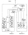
- Fig. 3 is a block diagram for explanation of the circuit structure of the projector 10.
- the control unit 1 there are provided a CPU 101, a memory 102, the operation member 103, a liquid crystal display unit 104, a speaker 105, an external interface (I/F) 106, and a power supply circuit 107; and a battery 108, a memory card 200, and a wireless communication unit 210 are also attached.
- a projection lens 121 To the projector unit 2, there are provided a projection lens 121, a liquid crystal panel 122, a LED light source 123, a projection control circuit 124, a lens drive circuit 125, and an attitude sensor 130.
- the CPU 101 Based upon a control program and functioning as a controller, the CPU 101 performs a predetermined calculation or the like using signals that are inputted from various sections that make up the projector 10, and controls the projection operation of the projector 10 by outputting control signals to various sections of the projector 10. It should be understood that this control program is stored in a non-volatile memory within the CPU 101, not shown in the figures. Furthermore, by employing image processing, the CPU 101 performs trapezoidal distortion compensation (keystone compensation) upon the image data that is projected by the projector 10.
- trapezoidal distortion compensation keystone compensation
- the memory 102 is used as a working memory for the CPU 101.
- the operation member 103 includes a main switch, a light source ON/OFF switch, and the like, and outputs actuation signals corresponding to these actuation switches to the CPU 101.
- the memory card 200 is constituted by a non-volatile memory, and is made so as to be removably fitted into a card slot 14 (see Fig. 1 ) of the control unit 1. It is possible to write, store, and read out data such as image data and audio data to and from this memory card 200, upon command from the CPU 101.
- the wireless communication unit 210 is made so as to be removably fitted to the control unit 1, and transmits data to and from an external device, upon command by the CPU 101.
- This data that is transmitted and received may be image data and/or audio data, or may be control data for the projector 10.
- the external interface 106 Upon command by the CPU 101, the external interface 106 transmits data to and from an external device via a cable or a cradle not shown in the figures.
- This data that is transmitted and received may be image data and/or audio data, or may be control data for the projector 10.
- the speaker 105 replays audio that has been outputted from the CPU 101 as a sound signal. And, upon command from the CPU 101, the liquid crystal display unit 104 displays information such as text or the like. Such text information may be information specifying the operational state of the projector 10, or an operation menu or the like.
- the battery 108 is constituted as a rechargeable secondary battery, and supplies electrical power to the various sections within the projector 10.
- the power supply circuit 107 includes a DC/DC conversion circuit, a charging circuit, and a voltage detection circuit, and, apart from converting the voltage of the battery 108 to the voltage(s) required by the various sections within the projector 10, also charges the battery 108 with a charging current that is supplied via the external interface (I/F) 106, if the voltage of the battery 108 has become low and its remaining capacity is decreased.
- An opening angle detection switch 110 detects the rotational angle of the hinge unit 3, and outputs an OFF signal to the CPU 101 if it detects that the relative angle ⁇ between the control unit 1 and the projector unit 2 is 0° (the storage attitude), while it outputs an ON signal if it detects any other relative angle.
- the projection control circuit 124 controls each of the liquid crystal panel 122, the LED light source 123, and the lens drive circuit 125.
- This projection control circuit 124 supplies electrical current to the LED light source 123, according to a LED drive signal that is outputted from the CPU 101.
- the LED light source 123 illuminates the liquid crystal panel 122 at a brightness corresponding to this supplied electrical current.
- the projection control circuit 124 generates a liquid crystal panel drive signal according to image data that is transmitted from the CPU 101, and drives the liquid crystal panel 122 with this generated drive signal.
- it applies a voltage corresponding to the image signal to each picture element in a liquid crystal layer.
- the arrangement of the liquid crystal molecules in this liquid crystal layer to which these voltages are applied changes, so that the transmittivity of the liquid crystal layer to light changes.
- the liquid crystal panel 122 creates an optical image.
- This liquid crystal panel 122 has an effective picture element region that is approximately square in shape, i.e. that consists of the same number of effective picture elements in the vertical and horizontal directions.
- the lens drive circuit 125 shifts the projection lens 121 forwards and backwards along a direction orthogonal to the optical axis, based upon a control signal outputted from the projection control circuit 124. And the projection lens 121 projects an optical image that is emitted from the liquid crystal panel 122 towards a screen or the like.
- the attitude sensor 130 detects the attitude of the projector unit 2, and outputs its detection signal to the CPU 101 via the projection control circuit 124. Due to this, the CPU 101 is able to decide whether the projector 10 is in the state of being in its storage attitude as shown in Fig. 1 , or is in any of the states shown in Fig. 2(a) through Fig. 2(c) .
- the CPU 101 changes the direction of emission of the ray bundle B by shifting the projection lens 121 in a direction orthogonal to the optical axis, and thereby offsets the projected image. And, if the CPU 101 has decided that the projector is in the state shown in Fig. 2(a) , then it causes the ray bundle B to be emitted in a direction somewhat away from the surface 1b, so that no portion of the ray bundle B strikes the chassis of the control unit 1. In other words, the CPU 101 shifts the projection lens 121 so that the upper edge of the ray bundle B is directed more downward than the prolongation of the surface 1b.
- the CPU 101 if it has decided that the apparatus is in the state shown in Fig. 2(c) , then it causes the ray bundle B to be emitted in a direction somewhat away from the prolongation of the surface 1b, so that no portion of the ray bundle B strikes the surface (not shown in the figure) upon which the projector is mounted. In other words, the CPU 101 shifts the projection lens 121 so that the lower edge of the ray bundle B is directed more upward than the prolongation of the surface 1b.
- the CPU 101 shifts the projection lens 121 so as to cause the ray bundle B to be emitted in a direction that is orthogonal with respect to the prolongation of the surface 1b.
- the projection lens 121 is shifted so as to cause the ray bundle B to be emitted in a direction that is orthogonal with respect to the prolongation of the surface 1a.
- this offsetting of the projected image is performed in some other manner than by shifting the projection lens 121, for example by shifting the liquid crystal panel 122 and the LED light source 123 in a direction that is orthogonal to the optical axis.
- it would be possible to implement offsetting of the projected image by changing the relative positional relationship between the projection lens 121 and the liquid crystal panel 122 in a direction that is orthogonal to the optical axis.
- the CPU 110 performs electronic keystone compensation by image processing the projected image in order to compensate it from a trapezoidal shape to a rectangular shape. For each of the situations shown in Figs. 2 (a) through 2(c), an initial compensation value is stored in advance within the CPU 101 for compensating the projected image to a rectangular shape.
- the CPU 101 performs keystone compensation processing upon the data for the projected image in the memory 102, based upon the appropriate one of these initial compensation values. It should be understood that it would also be acceptable to arrange to perform this keystone compensation processing, not only in the various states shown in Figs. 2(a) through 2(c) , but for any_angle ⁇ .
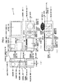
- Fig. 4(a) is a left side view
- Fig. 4(b) is a plan view
- Fig. 4(c) is an elevation view.
- a main circuit board 51, a power supply board 52, and the speaker 105 are disposed within the control unit 1, and the battery 108 is also included therein.
- the wireless communication unit 210 is installed upon a connector not shown in the figures that is provided upon the main circuit board 51, and the memory card 200 is likewise installed upon a card connector not shown in the figures that is provided upon the main circuit board 51.
- a connector 106A is also provided upon the main circuit board 51 for connection of the external interface (I/F) 106.
- a projection optical system 12 that includes the projection lens 121, a board 122A on which the liquid crystal panel 122 is provided, a condensing optical system 54, a board 123A one which the LED light source 123 is provided, and a heat dissipation member 53 that dissipates heat generated by the LED light source 123 upon the board 123A.
- the projection optical system 12 bends a ray bundle having passed through the liquid crystal panel 122 and progressing in the rightwards direction in Fig. 4 (c) within the projector unit 2 so as to emit it in the upwards direction.
- This projection optical system 12 is adapted to shift forwards or backwards along the direction of the optical axis (in the leftwards or rightwards direction in Figs. 4(b) and 4(c) ) according to the amount of operation of a focus adjustment operation member 13 shown in Fig. 4(b) , when this focus adjustment operation member 13 is operated by being slid in the leftwards or rightwards direction. Focus adjustment of the projected image is performed by this forwards and backwards shifting.
- the heat dissipation member 53 is formed from a material that has high thermal conductivity. Furthermore, this heat dissipation member 53 is integrated within the projector unit 2 with the hinge unit 3 so that, according to this structure, heat is conducted from the heat dissipation member 53 to the hinge unit 3.
- the heat dissipation member 53 is adapted, not only to dissipate heat from heat dissipation fins (not shown in the figures) that are formed upon its surface, but also to dissipate heat to the chassis of the projector unit 2.
- a mass of filler material 60 of high thermal conductivity may be charged between the heat dissipation member 53 and the chassis, or a sheet of material of high thermal conductivity may be sandwiched between them.
- the hinge unit 3 and the chassis of the control unit 1 are also constructed so as to conduct heat.
- a filler material (not shown in the figures) of high thermal conductivity may be charged between the hinge unit 3 and the chassis of the control unit 1, or a sheet of material of high thermal conductivity may be sandwiched between them.
- thermally insulating seals 65 that are formed from a material whose thermal insulation characteristic is high are adhered in the shape of bands (for example over a 2 mm gap) to the surfaces of the chassis of the control unit 1 and of the projector unit 2 close to the hinge unit 3, so that, with this structure, when the user grasps the projector 10, he does not directly touch the surface of its chassis.
- a temperature seal is adhered to the surface 2c of the projector unit 2.
- This temperature seal may, for example, be one upon which a character display "Caution: high temperature” emerges when the temperature of the surface upon which it is adhered reaches 40°C, while this display disappears when the temperature of the surface upon which it is adhered is below 40°C. It should be understood that it would also be acceptable for this temperature seal to be one upon which a number appears corresponding to the temperature of the surface upon which it is adhered, or one upon which a different color appears for each temperature stage of the surface upon which it is adhered.
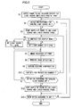
- a main processing program that is executed by the CPU 101 of the projector 10 described above will now be explained with reference to the flow chart of Fig. 5 .
- the processing of Fig. 5 is started when a main switch that is included in the operation member 103 is actuated so as to be turned to ON.
- the CPU 101 sends a command to the power supply circuit 107 so as to start supply of electrical power to the various portions of the projector, with the exception of the LED light source 123 and the liquid crystal panel 122, and then the flow of control proceeds to a step S2.
- the CPU 101 decides whether or not actuation for turning the light source ON (i. e. for starting projection) has been performed. If either an ON actuation signal from a light source ON/OFF switch that is included in the operation member 103 or an ON signal from the opening angle detection switch 110 has newly been inputted, then an affirmative decision is reached in this step S2, and the flow of control proceeds to a step S3, while if no such signal has been newly inputted a negative decision is reached in this step S2, and the flow of control proceeds to a step S13.
- step S3 the CPU 101 issues a command to the projection control circuit 124 and starts supply of electrical current to the LED light source 123 and to the liquid crystal panel 122, and then the flow of control proceeds to a step S4. Due to this, a ray bundle B is emitted from the projector 10, and an optical image is projected upon the screen.
- the projector 10 is adapted to project and replay contents selected from the following types of projection source contents.
- the CPU 101 selects the contents for projection according to a setting actuation signal from the operation member 103. And the CPU 101 transmits the data for the selected contents to the projection control circuit 124, and thereby an optical image corresponding to the data is generated upon the liquid crystal panel 122.
- step S4 the CPU 101 decides whether or not the contents for projection is "menu". If the CPU 101 is selecting "4" described above as the contents for projection, then an affirmative decision is taken in this step S4 and the flow of control proceeds to a step S6, while if "4" described above is not being selected, then a negative decision is taken in this step S4 and the flow of control proceeds to a step S5.
- step S5 the CPU 101 issues a command to the projection control circuit 124 to set the luminance of the light source to high (H) level, and then the flow of control proceeds to a step S7. Due to this, the value of the electrical current that is being supplied to the LED light source 123 is adjusted to high level, and the liquid crystal panel 122 is illuminated at high luminance as is appropriate for projection of an image.
- the CPU 101 issues a command to the projection control circuit 124 to set the luminance of the light source to low (L) level, and then the flow of control proceeds to the step S7. Due to this, the value of the electrical current that is being supplied to the LED light source 123 is adjusted to a somewhat lower level than during projection of an image, and the liquid crystal panel 122 is illuminated at low luminance as is appropriate for projection of text or the like.
- the CPU 101 performs checking of the attitude of the projector 10.
- the CPU 101 decides whether the projector 10 is in the storage attitude of Figs. 1(a) through 1(c) or any one the attitudes shown in Figs. 2(a) through 2(c) , and then the flow of control proceeds to the step S8.
- the CPU 101 performs offsetting processing for the projected image, and then the flow of control proceeds to a step S9.
- the CPU 101 issues a command to the projection control circuit 124 to shift the projection lens 121, so as to ensure that no portion of the ray bundle B strikes any potential obstruction, as described above.
- the data for the amount by which the projection lens 121 should be shifted is stored in advance within the CPU 101.
- the CPU 101 reads out the data for the amount by which the projection lens 121 should be shifted according to the state of the projector 10 that has been checked in the step S7, and sends a shift command along with this data to the projection control circuit 124.
- the CPU 101 performs keystone processing for the projected image, and then the flow of control proceeds to a step S10.
- the CPU 101 reads out an initial compensation value according to the state of the projector 10 that was checked in the step S7, and transmits the data for the image to be projected to the projection control circuit 124 after having performed keystone compensation thereupon using this compensation value.
- the CPU 101 decides whether or not the contents to be projected have been changed. If an actuation signal that changes the contents to be projected is being inputted from the operation member 103, then the CPU 101 reaches an affirmative decision in this step S10 and the flow of control returns to the step S4, whereas if no such actuation signal for changing the contents to be projected is being inputted, then the CPU reaches a negative decision in this step S10, and the flow of control proceeds to a step S11.
- the CPU 101 takes a decision as to whether or not actuation to turn the light source OFF (i.e. to terminate projection) is performed. If either an OFF actuation signal from the light source ON/OFF switch that is included in the operation member 103 or an OFF signal from the opening angle detection switch 110 is newly being inputted, then an affirmative decision is reached in this step S11, and the flow of control proceeds to a step S12, while if no such signal is being newly inputted then a negative decision is reached in this step S11, and the flow of control returns to the step S7. If the flow of control thus returns to the step S7, projection is continued while the attitude of the projector 10 is checked again.
- the CPU 101 issues a command to the projection control circuit 124 to stop supply of electrical power to the LED light source 123 and to the liquid crystal panel 122, and then the flow of control proceeds to a step S13. By doing this, the projection of the optical image from the projector 10 ceases. It should be understood that, since the supply of electrical power from the power supply board 52 to the various other circuitry upon the main circuit board 51 is continued, accordingly, if the source for the contents to be projected is "1" as described above, then the information of the memory card 200, and the data that has been read in from the memory card 200, are stored in the memory 102.
- the source for the contents to be projected is "2" as described above, then communication between the wireless communication unit 210 and the external device is continued, and the data that has been received by the wireless communication unit 210 are stored in the memory 102. Moreover, if the source for the contents to be projected is "3" as described above, then communication between the external interface 106 and the external device is continued, and the data that has been received by the external interface 106 are stored in the memory 102.
- step S13 a decision is made as to whether or not the main switch that is included in the operation member 103 is turned to OFF. If an OFF actuation signal is being inputted, then the CPU 101 makes an affirmative decision in this step S13, and performs power supply OFF processing and terminates supply of electrical power to the various sections upon the main circuit board 51, and then the processing shown in Fig. 5 is terminated. On the other hand, if no such OFF actuation signal is being inputted, then the CPU 101 makes a negative decision in this step S13, and the flow of control returns to the step S2.
- a time expired decision in the step S11 described above determines whether or not the light source is turned OFF (i.e. whether or not projection is to be terminated).
- a predetermined time period for example five minutes
- the CPU 101 would take this time expired signal as being a light source OFF actuation signal and would reach an affirmative decision in the step S11. By doing this, it would be possible to stop useless projection operation automatically, thus suppressing the consumption of electrical power and the accompanying generation of heat.
- step S12 it was arranged to stop the supply of electrical power to the LED light source 123 and to the liquid crystal panel 122, it would also be acceptable to arrange to provide a structure in which, while maintaining the supply of electrical power to the liquid crystal panel 122 just as it is, the electrical current that is being supplied to the LED light source 123 is reduced to a small level.
- this actuation switch is implemented as a slide switch, then it would be possible to arrange for sliding of this switch from its OFF position through one stage to be equivalent to turning the main switch ON (with the light source OFF), and for further sliding of this switch through a second stage to be equivalent to turning the light source ON (with the main switch also ON).
- both of the chassis of the projector 10 i.e. the chassis of the control unit 1 and also the chassis of the projector unit 2
- the control unit 1 and the projector unit 2 not necessarily to have the shape of a rectangular parallelepiped, provided that, at least, each of their chassis has a planar surface, with these planar surfaces being mutually opposed to one another.
- the rotation shaft of the hinge unit 3 should be perpendicular to both of these mutually opposing surfaces of the control unit 1 and of the projector unit 2.
- a main processing program that is executed by the CPU 101 of the projector 10 described above will now be explained with reference to the flow chart of Fig. 6 .
- the processing of Fig. 6 is started when a main switch that is included in the operation member 103 is operated so as to be turned to ON.
- the CPU 101 sends a command to the power supply circuit 107 so as to start supply of electrical power to the various portions of the projector, with the exception of the LED light source 123 and the liquid crystal panel 122, and then the flow of control proceeds to a step S102.
- the CPU 101 decides whether or not operation for turning the light source ON (i.e. for starting projection) has been performed. If either an ON actuation signal from a light source ON/OFF switch that is included in the operation member 103 or an ON signal from the opening angle detection switch 110 has newly been inputted, then an affirmative decision is reached in this step S102, and the flow of control proceeds to a step S103, while if no such signal has been newly inputted a negative decision is reached in this step S102, and the flow of control proceeds to a step S113.
- the CPU 101 issues a command to the projection control circuit 124 and starts supply of electrical current to the LED light source 123 and to the liquid crystal panel 122, and then the flow of control proceeds to a step S104. Due to this, a ray bundle B is emitted from the projector 10, and an optical image is projected upon the screen.
- the projector 10 is adapted to project and replay contents selected from the following types of projection source.
- the CPU 101 selects the contents for projection according to a setting operation signal from the operation member 103. And the CPU 101 transmits the data for the selected contents to the projection control circuit 124, and thereby an optical image corresponding to the data is generated upon the liquid crystal panel 122.
- the CPU 101 performs checking of the attitude of the projector 10.
- the CPU 101 decides upon which of the storage attitude shown in Figs. 1 (a) through 1(c) , and the attitudes of Figs. 2(a) through 2(c) the projector 10 is taken, and then the flow of control proceeds to a step S105.
- the CPU 101 makes a decision as to whether or not the attitude of the projector 10 has been changed. If the attitude of the projector 10 as decided upon in the step S104 is different from its attitude as decided upon in the previous pass through this procedure, then the CPU 101 arrives at an affirmative decision in this step S105 and the flow of control proceeds to a step S106, whereas if the attitude of the projector 10 on this pass through is the same as its attitude in the previous pass through, then the CPU 101 arrives at a negative decision in this step S105 and the flow of control is transferred to a step S107.
- the CPU 101 rotates the projected image. If in the step S104 it has been decided that the projector 10 is in the storage attitude shown in Figs. 1(a) through 1(c) , or in either the attitude shown in Fig. 2 (b) or the attitude shown in Fig. 2(c) , then in this step S106 the CPU 101 sends a command to the projection control circuit 124 to form upon the liquid crystal panel 122 an optical image that is normally oriented, in correspondence to the data for the contents to be projected.
- step S104 if in the step S104 it has been decided that the projector 10 is in the attitude shown in Fig. 2 (a) , then in this step S106 the CPU 101 sends a command to the projection control circuit 124 to rotate the image that is formed upon the liquid crystal panel 122 so that the optical image to be projected is rotated through 180° from the normal orientation.
- the CPU 101 performs offsetting processing for the projected image, and then the flow of control proceeds to a step S108.
- the CPU 101 issues a command to the projection control circuit 124 to shift the projection lens 121, so as to ensure that no portion of the ray bundle B strikes any potential obstruction, as described above.
- the data for the amount by which the projection lens 121 should be shifted is stored in advance within the CPU 101.
- the CPU 101 reads out the data for the amount by which the projection lens 121 should be shifted according to the state of the projector 10 that has been checked in the step S104, and sends a shift command along with this data to the projection control circuit 124.
- the CPU 101 performs keystone processing for the projected image, and then the flow of control proceeds to a step S109.
- the CPU 101 reads out an initial compensation value according to the state of the projector 10 that was checked in the step S104, and transmits the data for the image to be projected to the projection control circuit 124 after having performed keystone compensation thereupon using this compensation value.
- the CPU 101 makes a decision as to whether or not "the battery is low” or "the battery is insufficient", that indicate the state of electrical discharge of the battery 108. If the CPU 101 decides that "the battery is low” or “the battery is insufficient”, then it reaches an affirmative decision in the step S109 and the flow of control proceeds to a step S110; while, if the CPU 101 decides that "the battery is full” or “the battery is medium”, then it reaches a negative decision in the step S109 and the flow of control is transferred to a step S111.
- the CPU 101 sends a command to the projection control circuit 124 thereby creating and superimposing an image of a battery icon upon the optical image to be projected, and then the flow of control proceeds to the step S111.
- the CPU 101 creates an optical image upon the liquid crystal panel 122 upon which the battery icon is superimposed.
- the battery icon may be superimposed in the upper left of the image, so as to avoid the lower right of the image.
- the battery icon may be superimposed in the lower right of the image, so as to avoid the upper right and the lower left of the image.
- the CPU 101 colors the battery icon to be combined differently from the color of the contents image.
- the CPU 101 checks upon the contents image the color of the region in which the battery icon is to be superimposed (i.e. a color that is equivalent to the background color for the battery icon), creates a battery icon image using a color that is different from this background color, and superimposes this battery icon that it has created upon the contents image.
- the CPU 101 makes a decision as to whether or not actuation to turn the light source OFF (i.e. to terminate projection) is performed. If either an OFF actuation signal from the light source ON/OFF switch that is included in the operation member 103 or an OFF signal from the opening angle detection switch 110 is newly being inputted, then an affirmative decision is reached in this step S111, and the flow of control proceeds to a step S112, while if no such signal is being newly inputted then a negative decision is reached in this step S111, and the flow of control returns to the step S104. If the flow of control thus returns to the step S104, projection is continued while the attitude of the projector 10 and the state of the amount remaining in the battery 108 are checked again.
- the CPU 101 issues a command to the projection control circuit 124 to stop supply of electrical power to the LED light source 123 and to the liquid crystal panel 122, and then the flow of control proceeds to a step S113. By doing this, the projection of the optical image from the projector 10 ceases.
- the various other circuitry such as the CPU 101 and, as well, the memory 102, the memory card 200, the wireless communication unit 210, the external interface 106 and the like is continued, accordingly, if the source for the contents to be projected is Source 1 as described above, then the information of the memory card 200, and the data that has been read in from the memory card 200, are stored in the memory 102.
- the source for the contents to be projected is Source 2 as described above, then communication between the wireless communication unit 210 and the external device is continued, and the data that has been received by the wireless communication unit 210 are stored in the memory 102. Moreover, if the source for the contents to be projected is Source 3 as described above, then communication between the external interface 106 and the external device is continued, and the data that has been received by the external interface 106 are stored in the memory 102.
- step S113 a decision is made as to whether or not the main switch that is included in the operation member 103 is turned OFF. If an OFF actuation signal is being inputted, then the CPU 101 makes an affirmative decision in this step S113, and performs power supply OFF processing and terminates supply of electrical power to the various sections, and then the processing shown in Fig. 6 is terminated. On the other hand, if no such OFF actuation signal is being inputted, then the CPU 101 makes a negative decision in this step S113, and the flow of control returns to the step S102.
- Slide show processing starts, if the source 1 described above for the contents to be projected is selected, and moreover an actuation signal that commands slide show projection starts is inputted to the CPU 101 from the operation member 103 during projection according to the main processing routine shown in Fig. 6 (i.e. the steps S103 through S111).
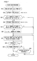
- Fig. 7 is a flow chart for explanation of the processing flow during such slide show processing.
- a step S21 of Fig. 7 the CPU 101 reads out remaining capacity data A ⁇ h for the battery 108 from a lookup table (LUT), and then the flow of control proceeds to a step S22.
- This LUT consists of a relationship between the voltage of the battery 108 and its remaining capacity that is actually measured in advance, this relationship being converted into a table and being stored in a non-volatile memory (not shown in the figures) within the CPU 101.
- the CPU 101 reads out the remaining capacity data A ⁇ h from this LUT by using as an argument the value of the voltage of the battery 108, as detected by battery check processing that will be described hereinafter.
- the electrical current In is the average value of electrical current consumption over a predetermined immediately precedent time period (for example during the last ten seconds), and this is transmitted to the CPU 101 from the power supply circuit 107 as electrical current consumption information.
- the flow of control proceeds to a step S23.
- the CPU 101 decides whether or not the condition that the estimated time period R over which projection is possible ⁇ (number of frames x standard projection time period tn for one frame) holds.
- the number of frames is the number of images for which projection by a slide show is commanded. This number of frames is commanded according to the actuation signal from the operation member 103. If the above condition holds, then the CPU 101 reaches an affirmative decision in this step S23 and the flow of control is transferred to a step S27, whereas, if the above condition does not hold, then the CPU 101 reaches a negative decision in this step S23 and the flow of control proceeds to a step S24.
- step S24 this is the case in which an estimation has been reached that, partway through the projection of the slide show, the remaining capacity of the battery 108 will be insufficient.
- step S27 this is the case in which the necessary remaining capacity of the battery 108 for projecting the slide show is assured. If the flow of control is transferred to the step S27, then the CPU 101 sends a command to the projection control circuit 124, and maintains the present electrical current value that is being supplied to the LED light source 123.
- the electrical current Is is the amount of electrical current that is consumed during electrical current economization, and, for example, may be 70% of the most recent electrical current consumption In described above.
- step S25 the CPU 101 makes a decision as to whether or not the condition that this new estimated time period Rs over which projection is possible ⁇ (number of frames x standard projection time period tn for one frame) holds. If the above condition holds, then the CPU 101 reaches an affirmative decision in this step S25 and the flow of control is transferred to the step S27, whereas, if the above condition does not hold, then the CPU 101 reaches a negative decision in this step S25 and the flow of control proceeds to a step S26. If the flow of control thus proceeds to the step S26, then this is the case in which, even if the electrical power consumption is economized, nevertheless, partway through the projection of the slide show, the remaining capacity of the battery 108 will be insufficient.
- the CPU 101 sends a command to the projection control circuit 124 and decreases the electrical current value that is being supplied to the LED light source 123, so that the overall consumption of electrical current is decreased to 70% of the most recent value of consumed electrical current In.
- the CPU 101 further sends a command to the projection control circuit 124, so as to perform image processing such as gamma compensation or the like in order to compensate for the decrease of projection luminance due to this reduction of the electrical current supplied to the LED light source 123.
- step S27 the CPU 101, along with reading out the image data from the memory card 200, also sends data for display by projection to the projection control circuit 124 and commands the circuit 124 to project a replay image based thereupon; and then the flow of control proceeds to a step S28. Due to this, a replay image is projected by the projector 10.
- step S28 the CPU 101 decides whether or not time up has taken place. And, if the above described standard projection time period tn (or the shortened projection time period ts, if the flow of control has arrived at this point via the step S26) has elapsed, then the CPU 101 reaches an affirmative decision in this step S28 and the flow of control proceeds to a step S29, whereas if time up has not yet occurred then the CPU 101 reaches a negative decision in this step S28 and repeats the same decision processing.
- step S29 the CPU 101 makes a decision as to whether or not projection of all the frames has been completed. And, if projection has been completed for images of all of the frames that were commanded to be projected in this slide show, then the CPU 101 reaches an affirmative decision in this step S29, and the slide show processing shown in Fig. 7 is terminated. On the other hand if projection has not been completed for all of the frames, then the CPU 101 reaches a negative decision in this step S29, and the flow of control proceeds to a step S30.
- step S30 the CPU 101 makes a decision as to whether or not stopping actuation has been performed. If an actuation signal has been inputted from the operation member 103 to stop projection of the slide show, then the CPU 101 reaches an affirmative decision in this step S30, and the slide show processing shown in Fig. 7 is terminated. On the other hand, if no such actuation signal has been inputted from the operation member 103 to stop projection of the slide show, then the CPU 101 reaches a negative decision in this step S30, and the flow of control returns to the step S27.
- the CPU 101 along with reading out image data for the next frame from the memory card 200, also sends this data for projection display to the projection control circuit 124 and commands projection of a replay image, and then the flow of control proceeds to the step S28. Due to this, a replay image for the next frame is projected from the projector 10.
- This battery check processing of Fig. 8 is started periodically at predetermined time intervals as interrupt processing, even during execution of the flow chart of Fig. 6 (the main procedure) or during execution of the flow chart of Fig. 7 (slide show processing).
- step S51 of Fig. 8 the CPU 101 performs a voltage check of the battery 108, and then the flow of control proceeds to a step S52.
- This voltage check is performed by inputting the detection signal that is detected by the power supply circuit 107.
- the CPU 101 decides whether or not the voltage of the battery 108 is, for example, greater than or equal to 3.5 V. If a voltage of greater than or equal to 3.5 V is detected, then the CPU 101 reaches an affirmative decision in this step S52 and the flow of control proceeds to a step S53, whereas, if the detected voltage is less than 3. 5 V, then the CPU 101 reaches a negative decision in this step S52 and the flow of control proceeds to a step S54.
- step S53 the CPU 101 decides that the battery 108 is fully charged (in the case of the primary battery, that its electrical discharge proportion is approximately 0%), and a battery icon that shows "battery full” (i.e. with all three segments illuminated) is decided upon and the processing of Fig. 8 terminates.
- this battery icon that shows "battery full” is not particularly utilized.
- the CPU 101 decides whether or not the voltage of the battery 108 is, for example, greater than or equal to 3.0 V and less than 3.5 V. If a voltage between 3.0 V and 3.5 V is detected, then the CPU 101 reaches an affirmative decision in this step S54 and the flow of control proceeds to a step S55, whereas, if the detected voltage is less than 3.0 V, then the CPU 101 reaches a negative decision in this step S54 and the flow of control proceeds to a step S56.
- the CPU 101 decides that the charge proportion of the battery 108 is medium (in the case of the primary battery, that its electrical discharge proportion is approximately 50%), and a battery icon that shows "battery medium” (i.e. with two segments illuminated and one segment not illuminated) is decided upon and the processing of Fig. 8 terminates.
- this battery icon that shows "battery medium” is not particularly utilized.
- the CPU 101 decides whether or not the voltage of the battery 108 is, for example, greater than or equal to 2.7 V and less than 3.0 V. If a voltage between 2.7 V and 3.0 V is detected, then the CPU 101 reaches an affirmative decision in this step S56 and the flow of control proceeds to a step S57, whereas, if the detected voltage is less than 2.7 V, then the CPU 101 reaches a negative decision in this step S56 and the flow of control proceeds to a step S58.
- the CPU 101 decides that the charge proportion of the battery 108 is low (in the case of the primary battery, that its electrical discharge proportion is approximately 70%), and a battery icon that shows "battery low” (i.e. with one segment illuminated and two segments not illuminated) is decided upon and the processing of Fig. 8 terminates.
- This battery icon that shows "battery low” is utilized in the step S110 of Fig. 6 .
- the CPU 110 decides whether or not the voltage of the battery 108 is, for example, greater than or equal to 2.5 V and less than 2.7 V. If a voltage between 2.5 V and 2.7 V is detected, then the CPU 101 reaches an affirmative decision in this step S58 and the flow of control proceeds to a step S59, whereas, if the detected voltage is less than 2.5 V, then the CPU 101 reaches a negative decision in this step S58 and the flow of control proceeds to a step S60.
- the CPU 101 decides that the charge proportion of the battery 108 is extremely low (in the case of the primary battery, that its electrical discharge proportion is approximately 90%), and a battery icon that shows "battery insufficient" (i.e. with all three of its segments not illuminated and with its frame blinking) is decided upon and the processing of Fig. 8 terminates.
- This battery icon that shows "battery insufficient” is utilized in the step S110 of Fig. 6 .
- step S60 the system is in a state in which the voltage of the battery 108 does not attain the necessary voltage for operating the various sections of the projector 10 (i.e. its remaining capacity is insufficient). Accordingly, in this step S60, the CPU 101 makes a decision as to whether or not a slide show is being projected. If the system is performing the slide show processing of Fig. 7 , then the CPU 101 reaches an affirmative decision in this step S60 and the flow of control proceeds to a step S61, whereas, if the slide show processing of Fig. 7 is not being performed, then the CPU 101 reaches a negative decision in this step S60 and the flow of control proceeds to a step S62.
- step S61 the CPU 101 stores, in a non-volatile memory within the CPU 101, information that specifies the frame to be projected (for example, the title of its image data file), and information that specifies the frames that have not yet been projected, for slide show processing next time when the starting of slide show projection is commanded after the battery 108 has been exchanged for another fully charged battery (or the battery 108 itself has been charged up) ; and then the flow of control proceeds to the step S62.
- information that specifies the frame to be projected for example, the title of its image data file
- step S62 the CPU 101 performs power supply OFF processing in which the supply of electrical power to the various sections of the apparatus is turned OFF, and then the processing of Fig. 8 is terminated. Due to this, before the voltage of the battery 108 becomes absolutely insufficient and the CPU 101 actually becomes inoperable, the necessary information is stored and then power supply OFF processing is performed.
- the voltage values specified above for the battery 108 are only given by way of example; these decision reference voltages should be changed as appropriate, according to the type of the battery 108 that is used.
- a structure may be employed in which, during slide show processing, the battery icon is synthesized and superimposed upon the images that is being projected for slide show as well.
- the size of the image of the contents to be projected may be varied so that the image is projected at, for example, a 10% reduced size.
- a battery icon or a message that notifies the user that the voltage of the battery 108 has decreased may be projected. Since, with this type of structure, the battery icon or the message is not superimposed over the image of the contents to be projected, accordingly it remains easy to view the contents being projected.
- the CPU 101 would take advantage of the information for replay time period that is included in such a moving image file, and would economize upon the electrical current consumption (i.e. would decrease the value of the electrical current that is supplied to the LED light source 123) so as to fit this replay time period within the time period that it is estimated that projection is possible, based upon the voltage of the battery 108 that is detected.
- the optical image formation element was constructed using the liquid crystal panel 122, and an optical image was obtained by illuminating an image formed upon the liquid crystal panel 122 with light from the LED light source 123, it would alsobe acceptable to arrange to utilize an optical image formation element of a type that itself emits light. In this case, the light source would be provided by this optical image formation element.
- Such an optical image formation element creates an optical image by causing point light sources that correspond to picture elements to emit light for each picture element, in accordance with an image signal.
- the present invention can also be applied to any electronic device that is battery driven and that is equipped with a projector, for example, to a portable telephone device equipped with a projector, or to a camera equipped with a projector or the like.
Landscapes
- Physics & Mathematics (AREA)
- General Physics & Mathematics (AREA)
- Engineering & Computer Science (AREA)
- Signal Processing (AREA)
- Multimedia (AREA)
- Optics & Photonics (AREA)
- Projection Apparatus (AREA)
Claims (11)
- Projektionsvorrichtung mit:einer Projektoreinheit (2), welche mindestens eine Lichtquelle (123) und ein optisches Projektionssystem (12) umfasst, die in einem Chassis untergebracht sind,einer Steuereinheit (1) welche an einem Chassis aufgebaut ist, das von dem Chassis der Projektoreinheit getrennt ist , undeinem Drehlagerglied (3) welches die Projektoreinheit und die Steuereinheit um eine Drehachse drehbar lagert, die sich senkrecht zu einer Oberfläche des Chassis der Projektoreinheit und einer Oberfläche des Chassis der Steuereinheit erstreckt, wobei diese Oberflächen einander gegenüber liegen, dadurch gekennzeichnet,dass das Drehlagerglied nur an einem Ende der Projektoreinheit in einer Längsrichtung der Projektoreinheit vorgesehen ist, unddas optische Projektionssystem in der Längsrichtung zum anderen Ende der Projektoreinheit hin vorgesehen ist, gegenüber dem Ende an dem das Drehlagerglied vorgesehen ist,wobei die Steuereinheit (1) die Lichtquelle (123) derart steuert, dass diese entsprechend einem Drehwinkel des Drehlagerglieds (3) ein- oder ausgeschaltet wird.
- Projektionsvorrichtung nach Anspruch 1, bei welcher:die optische Projektionsachse der Projektoreinheit (2) in einer Ebene enthalten ist,die senkrecht zur Drehachse des Drehlagerglieds (3) steht.
- Projektionsvorrichtung nach Anspruch 1 oder Anspruch 2, bei welcher:die Projektoreinheit (2) des weiteren ein Wärme abführendes Glied (53) umfasst,das die von der Lichtquelle erzeugte Wärme abführt, unddie Steuereinheit des weiteren eine Batterie (108) umfasst.
- Projektionsvorrichtung nach einem der Ansprüche 1 bis 3, bei welcher:die Steuereinheit (1) entsprechend einem Befehl zum Ausschalten der Lichtquelle eine Versorgung der Projektoreinheit (2) mit elektrischer Energie unterbricht oder begrenzt, während sie eine Versorgung mit elektrischer Energie innerhalb der Steuereinheit aufrecht erhält.
- Projektionsvorrichtung nach Anspruch 4, bei welcher:die Steuereinheit (1) gemäß einem Schlusszeit-Signal die Versorgung der Projektoreinheit (2) mit elektrischer Energie unterbricht oder begrenzt, während sie die Versorgung mit elektrischer Energie innerhalb der Steuereinheit aufrecht erhält.
- Projektionsvorrichtung nach Anspruch 3, bei welcher:das Drehlagerglied (3) und das Wärme abführende Glied (53) der Projektoreinheit gemeinsam zur Leitung von Wärme integriert sind.
- Projektionsvorrichtung nach Anspruch 3 oder Anspruch 6, bei welcher:das Wärme abführende Glied (53) zur Leitung von Wärme an eine Innenseite einer der Steuereinheit (1) gegenüber liegenden Oberfläche (2c) der Projektoreinheit (2) angeortnet ist.
- Projektionsvorrichtung nach einem der Ansprüche 3, 6 und 7, bei welcher:eine Anzeige, die einer Oberflächentemperatur entspricht, auf einer Chassisoberfläche der Projektoreinheit (2) der Steuereinheit (1) angeordnet ist.
- Projektionsvorrichtung nach einem der Ansprüche 3 und 6 bis 8, bei welcher:eine Dichtung aus einem thermisch isolierenden Material in der Form eines Bandes an eine Oberfläche mindestens des Chassis der Projektoreinheit (2) oder des Chassis der Steuereinheit (1) aufgeklebt ist.
- Projektionsvorrichtung nach einem der Ansprüche 1 bis 9, bei welcher:das Drehlagerglied (3) derart ausgelegt ist, dass die Projektoreinheit (2) in einer von mehreren diskreten Winkelpositionen in Bezug auf die Steuereinheit (1), gehalten werden kann.
- Projektionsvorrichtung nach einem der Ansprüche 1 bis 10, bei welcher:das Drehlagerglied (3) derart angeordnet ist, dass die Drehachse sich senkrecht zu einer Längsrichtung der Projektoreinheit (2) und einer Längsrichtung der Steuereinheit (1) erstreckt.
Applications Claiming Priority (3)
| Application Number | Priority Date | Filing Date | Title |
|---|---|---|---|
| JP2005193899A JP4244967B2 (ja) | 2005-07-01 | 2005-07-01 | 投影装置 |
| JP2005263660A JP4306661B2 (ja) | 2005-09-12 | 2005-09-12 | 投影装置 |
| PCT/JP2006/312999 WO2007004512A1 (ja) | 2005-07-01 | 2006-06-29 | 投影装置 |
Publications (3)
| Publication Number | Publication Date |
|---|---|
| EP1903387A1 EP1903387A1 (de) | 2008-03-26 |
| EP1903387A4 EP1903387A4 (de) | 2009-07-22 |
| EP1903387B1 true EP1903387B1 (de) | 2011-01-26 |
Family
ID=37604380
Family Applications (1)
| Application Number | Title | Priority Date | Filing Date |
|---|---|---|---|
| EP06767616A Not-in-force EP1903387B1 (de) | 2005-07-01 | 2006-06-29 | Projektionsvorrichtung |
Country Status (4)
| Country | Link |
|---|---|
| US (1) | US7938548B2 (de) |
| EP (1) | EP1903387B1 (de) |
| DE (1) | DE602006019866D1 (de) |
| WO (1) | WO2007004512A1 (de) |
Families Citing this family (23)
| Publication number | Priority date | Publication date | Assignee | Title |
|---|---|---|---|---|
| JP5040492B2 (ja) * | 2007-07-13 | 2012-10-03 | セイコーエプソン株式会社 | プロジェクタおよび輝度調整方法 |
| KR101390082B1 (ko) | 2007-08-01 | 2014-05-28 | 삼성전자주식회사 | 프로젝터를 구비하는 이동통신 단말기 |
| JP5241179B2 (ja) * | 2007-09-07 | 2013-07-17 | キヤノン株式会社 | 投射型表示装置 |
| JP2009237197A (ja) * | 2008-03-27 | 2009-10-15 | Sanyo Electric Co Ltd | 携帯プロジェクタ装置 |
| US20110109613A1 (en) * | 2008-07-15 | 2011-05-12 | Mitsumi Electric Co., Ltd. | Mobile device, battery pack, semiconductor device, display control method, and display control program |
| TW201022824A (en) * | 2008-12-08 | 2010-06-16 | Coretronic Corp | Projection apparatus |
| TWI409693B (zh) * | 2010-01-15 | 2013-09-21 | Micro Star Int Co Ltd | A method of advising the battery power state |
| JP5489748B2 (ja) * | 2010-01-27 | 2014-05-14 | 三菱電機株式会社 | 光源装置、投射型映像表示装置 |
| WO2011111363A1 (ja) * | 2010-03-09 | 2011-09-15 | パナソニック株式会社 | プロジェクタ |
| JP5609561B2 (ja) | 2010-11-10 | 2014-10-22 | ソニー株式会社 | 投影装置 |
| JP5606895B2 (ja) * | 2010-12-16 | 2014-10-15 | 三洋電機株式会社 | 投写型表示装置 |
| CN103034027B (zh) * | 2011-09-30 | 2015-03-11 | 中强光电股份有限公司 | 投影机及其光源控制方法 |
| US8718716B2 (en) * | 2012-05-23 | 2014-05-06 | Steven Earl Kader | Method of displaying images while charging a smartphone |
| CN103051782B (zh) * | 2012-12-10 | 2016-03-23 | 广东欧珀移动通信有限公司 | 一种移动终端投影调整方法及装置 |
| JP6205776B2 (ja) * | 2013-03-22 | 2017-10-04 | カシオ計算機株式会社 | 電子機器、プログラム及び選択許否決定方法 |
| US9699282B2 (en) * | 2013-03-29 | 2017-07-04 | Beijing Lenovo Software Ltd. | Electronic apparatus and control method |
| CN104714809B (zh) * | 2013-12-11 | 2018-11-13 | 联想(北京)有限公司 | 一种信息处理的方法及电子设备 |
| TWI537673B (zh) * | 2014-04-30 | 2016-06-11 | 中強光電股份有限公司 | 投影光學系統及用於投影光學系統的能量控制方法 |
| JP6631273B2 (ja) * | 2016-01-25 | 2020-01-15 | 株式会社リコー | 画像投射装置 |
| CN110855963B (zh) * | 2018-08-21 | 2022-03-08 | 视联动力信息技术股份有限公司 | 一种视频数据的投影方法和装置 |
| JP6648241B1 (ja) | 2018-11-13 | 2020-02-14 | 富士フイルム株式会社 | 投射装置 |
| JP6621899B1 (ja) | 2018-11-13 | 2019-12-18 | 富士フイルム株式会社 | 投射装置 |
| CN114143522A (zh) * | 2021-11-30 | 2022-03-04 | 歌尔光学科技有限公司 | 投影设备的温度控制方法、装置及投影设备 |
Family Cites Families (33)
| Publication number | Priority date | Publication date | Assignee | Title |
|---|---|---|---|---|
| JPS60162236A (ja) | 1984-02-03 | 1985-08-24 | Fuji Photo Film Co Ltd | ランプハウスの安全表示装置 |
| US5136397A (en) * | 1989-10-31 | 1992-08-04 | Seiko Epson Corporation | Liquid crystal video projector having lamp and cooling control and remote optics and picture attribute controls |
| JPH04195129A (ja) * | 1990-11-28 | 1992-07-15 | Olympus Optical Co Ltd | カメラ |
| JPH04319930A (ja) | 1991-04-19 | 1992-11-10 | Matsushita Electric Ind Co Ltd | ライトバルブ映像投写器の映像制御装置 |
| US5847748A (en) * | 1993-03-11 | 1998-12-08 | Ncr Corporation | Multimedia projection system |
| US20050007514A1 (en) * | 1994-04-21 | 2005-01-13 | Faris Sadeg M. | Backlighting construction for use in computer-based display systems having direct and projection viewing modes of operation |
| JP3680395B2 (ja) | 1995-12-20 | 2005-08-10 | 日亜化学工業株式会社 | 面状発光装置及びその駆動方法 |
| JPH09319006A (ja) | 1996-05-29 | 1997-12-12 | Nec Corp | ランプユニット及びランプ |
| JPH10224684A (ja) * | 1997-02-10 | 1998-08-21 | Nikon Corp | 情報処理装置 |
| JPH10333247A (ja) * | 1997-06-04 | 1998-12-18 | Matsushita Electric Ind Co Ltd | 投写型表示装置 |
| US6501429B2 (en) * | 1998-02-02 | 2002-12-31 | Seiko Epson Corporation | Portable information processing apparatus |
| JP2000148306A (ja) | 1998-11-06 | 2000-05-26 | Matsushita Electric Ind Co Ltd | 電子機器筐体構造 |
| JP2000236375A (ja) | 1999-02-12 | 2000-08-29 | Matsushita Electric Ind Co Ltd | プロジェクタ付携帯電話装置 |
| JP4443660B2 (ja) * | 1999-02-26 | 2010-03-31 | パナソニック株式会社 | 情報処理装置 |
| JP2000339053A (ja) | 1999-05-26 | 2000-12-08 | Hitachi Ltd | 表示メモリ内容の退避回復方法および装置 |
| WO2001096940A1 (en) * | 2000-06-13 | 2001-12-20 | Derryberry Eddie W | Electronic image projection device |
| JP2002077377A (ja) * | 2000-08-29 | 2002-03-15 | Toshiba Corp | 携帯端末装置および携帯端末装置の消費電力抑制方法 |
| JP2002091417A (ja) | 2000-09-12 | 2002-03-27 | Fujitsu Ltd | 画像表示装置 |
| US20020063855A1 (en) * | 2000-11-29 | 2002-05-30 | Williams John W. | Digital projection system for phones and personal digital assistants |
| JP2003084368A (ja) | 2001-09-10 | 2003-03-19 | Tamron Co Ltd | プロジェクタ |
| JP2003149633A (ja) | 2001-11-12 | 2003-05-21 | Nec Viewtechnology Ltd | 液晶プロジェクタの検光子保護方法及び検光子保護装置 |
| JP3931636B2 (ja) * | 2001-11-14 | 2007-06-20 | セイコーエプソン株式会社 | 電池駆動式プロジェクタの電池の残容量に応じた制御 |
| JP2003248463A (ja) | 2002-02-25 | 2003-09-05 | Matsushita Electric Ind Co Ltd | 液晶表示装置 |
| JP4002776B2 (ja) * | 2002-03-19 | 2007-11-07 | オリンパス株式会社 | 投影表示装置 |
| JP2004069997A (ja) | 2002-08-06 | 2004-03-04 | Seiko Epson Corp | プロジェクタシステム並びにプロジェクタ及び情報処理装置 |
| JP4181846B2 (ja) | 2002-10-25 | 2008-11-19 | キヤノン株式会社 | 記録再生装置及びその再生方法 |
| US20050012909A1 (en) * | 2003-02-21 | 2005-01-20 | Kokin Daniel E. | Projection system with flexible orientation |
| JP2005055812A (ja) * | 2003-08-07 | 2005-03-03 | Olympus Corp | プロジェクタ装置及びそれを組み込んだ机 |
| JP2005084075A (ja) | 2003-09-04 | 2005-03-31 | Nec Viewtechnology Ltd | 階調補正装置及び階調補正方法 |
| DE202004000110U1 (de) | 2004-01-07 | 2004-08-19 | Trw Automotive Electronics & Components Gmbh & Co. Kg | Vorrichtung zur Befestigung eines Bauteils an einem Mantelrohr |
| JP2005263660A (ja) | 2004-03-17 | 2005-09-29 | Shiseido Co Ltd | 尿素含有皮膚外用剤 |
| EP1793588A4 (de) * | 2004-09-21 | 2011-04-27 | Nikon Corp | Mobile informationsvorrichtung |
| JP4670602B2 (ja) * | 2005-11-16 | 2011-04-13 | セイコーエプソン株式会社 | プロジェクションシステム、プロジェクタ、および情報処理装置 |
-
2006
- 2006-06-29 DE DE602006019866T patent/DE602006019866D1/de active Active
- 2006-06-29 EP EP06767616A patent/EP1903387B1/de not_active Not-in-force
- 2006-06-29 WO PCT/JP2006/312999 patent/WO2007004512A1/ja not_active Ceased
- 2006-06-29 US US11/988,078 patent/US7938548B2/en active Active
Also Published As
| Publication number | Publication date |
|---|---|
| EP1903387A1 (de) | 2008-03-26 |
| EP1903387A4 (de) | 2009-07-22 |
| US7938548B2 (en) | 2011-05-10 |
| WO2007004512A1 (ja) | 2007-01-11 |
| DE602006019866D1 (de) | 2011-03-10 |
| US20090141245A1 (en) | 2009-06-04 |
Similar Documents
| Publication | Publication Date | Title |
|---|---|---|
| EP1903387B1 (de) | Projektionsvorrichtung | |
| US20220377293A1 (en) | Projection device | |
| EP1791329A1 (de) | Elektronische vorrichtung | |
| US20090027570A1 (en) | Electronic Device | |
| US8104900B2 (en) | Electronic device incorporating projector device | |
| US20090016710A1 (en) | Electronic Device | |
| WO2007029805A1 (ja) | プロジェクタ付き電子機器 | |
| CN101006390A (zh) | 电子设备 | |
| US20090033888A1 (en) | Projecting Apparatus | |
| JP4306661B2 (ja) | 投影装置 | |
| US11800208B2 (en) | Image capturing apparatus that is reduced in size and has high operability, and operation member | |
| JP2010074477A (ja) | 電子機器 | |
| EP1914593A1 (de) | Hilfsvorrichtung für eine projektionsvorrichtung und projektionssystem | |
| JP2010217825A (ja) | 投写型画像表示装置 | |
| EP2498164A2 (de) | Bildanzeigevorrichtung und mobile Informationsverarbeitungsvorrichtung damit | |
| JP2010191270A (ja) | 撮影装置 | |
| JP4244967B2 (ja) | 投影装置 | |
| JP2006175607A (ja) | プリントシステム | |
| JP2008288682A (ja) | 載置台 | |
| CN101006708A (zh) | 电子设备 | |
| JP2011227396A (ja) | 投写型映像表示装置 | |
| JP2006115485A (ja) | 電子機器 | |
| JP2008252480A (ja) | プロジェクタ付きカメラ | |
| JP2011176643A (ja) | 携帯ユニット及び携帯電子機器 | |
| JP4485391B2 (ja) | カメラ、カメラシステムおよび電子機器 |
Legal Events
| Date | Code | Title | Description |
|---|---|---|---|
| PUAI | Public reference made under article 153(3) epc to a published international application that has entered the european phase |
Free format text: ORIGINAL CODE: 0009012 |
|
| 17P | Request for examination filed |
Effective date: 20080124 |
|
| AK | Designated contracting states |
Kind code of ref document: A1 Designated state(s): AT BE BG CH CY CZ DE DK EE ES FI FR GB GR HU IE IS IT LI LT LU LV MC NL PL PT RO SE SI SK TR |
|
| DAX | Request for extension of the european patent (deleted) | ||
| DAX | Request for extension of the european patent (deleted) | ||
| A4 | Supplementary search report drawn up and despatched |
Effective date: 20090622 |
|
| RIC1 | Information provided on ipc code assigned before grant |
Ipc: H04M 11/00 20060101ALI20090616BHEP Ipc: G02F 1/13 20060101ALI20090616BHEP Ipc: G03B 21/14 20060101AFI20070306BHEP Ipc: G02F 1/1333 20060101ALI20090616BHEP Ipc: G03B 21/00 20060101ALI20090616BHEP |
|
| 17Q | First examination report despatched |
Effective date: 20090710 |
|
| RAP1 | Party data changed (applicant data changed or rights of an application transferred) |
Owner name: NIKON CORPORATION |
|
| GRAP | Despatch of communication of intention to grant a patent |
Free format text: ORIGINAL CODE: EPIDOSNIGR1 |
|
| GRAS | Grant fee paid |
Free format text: ORIGINAL CODE: EPIDOSNIGR3 |
|
| GRAA | (expected) grant |
Free format text: ORIGINAL CODE: 0009210 |
|
| AK | Designated contracting states |
Kind code of ref document: B1 Designated state(s): AT BE BG CH CY CZ DE DK EE ES FI FR GB GR HU IE IS IT LI LT LU LV MC NL PL PT RO SE SI SK TR |
|
| REG | Reference to a national code |
Ref country code: GB Ref legal event code: FG4D |
|
| REG | Reference to a national code |
Ref country code: CH Ref legal event code: EP |
|
| REG | Reference to a national code |
Ref country code: IE Ref legal event code: FG4D |
|
| REF | Corresponds to: |
Ref document number: 602006019866 Country of ref document: DE Date of ref document: 20110310 Kind code of ref document: P |
|
| REG | Reference to a national code |
Ref country code: DE Ref legal event code: R096 Ref document number: 602006019866 Country of ref document: DE Effective date: 20110310 |
|
| REG | Reference to a national code |
Ref country code: NL Ref legal event code: VDEP Effective date: 20110126 |
|
| LTIE | Lt: invalidation of european patent or patent extension |
Effective date: 20110126 |
|
| PG25 | Lapsed in a contracting state [announced via postgrant information from national office to epo] |
Ref country code: LT Free format text: LAPSE BECAUSE OF FAILURE TO SUBMIT A TRANSLATION OF THE DESCRIPTION OR TO PAY THE FEE WITHIN THE PRESCRIBED TIME-LIMIT Effective date: 20110126 Ref country code: GR Free format text: LAPSE BECAUSE OF FAILURE TO SUBMIT A TRANSLATION OF THE DESCRIPTION OR TO PAY THE FEE WITHIN THE PRESCRIBED TIME-LIMIT Effective date: 20110427 Ref country code: PT Free format text: LAPSE BECAUSE OF FAILURE TO SUBMIT A TRANSLATION OF THE DESCRIPTION OR TO PAY THE FEE WITHIN THE PRESCRIBED TIME-LIMIT Effective date: 20110526 Ref country code: IS Free format text: LAPSE BECAUSE OF FAILURE TO SUBMIT A TRANSLATION OF THE DESCRIPTION OR TO PAY THE FEE WITHIN THE PRESCRIBED TIME-LIMIT Effective date: 20110526 Ref country code: ES Free format text: LAPSE BECAUSE OF FAILURE TO SUBMIT A TRANSLATION OF THE DESCRIPTION OR TO PAY THE FEE WITHIN THE PRESCRIBED TIME-LIMIT Effective date: 20110507 Ref country code: SE Free format text: LAPSE BECAUSE OF FAILURE TO SUBMIT A TRANSLATION OF THE DESCRIPTION OR TO PAY THE FEE WITHIN THE PRESCRIBED TIME-LIMIT Effective date: 20110126 Ref country code: LV Free format text: LAPSE BECAUSE OF FAILURE TO SUBMIT A TRANSLATION OF THE DESCRIPTION OR TO PAY THE FEE WITHIN THE PRESCRIBED TIME-LIMIT Effective date: 20110126 |
|
| PG25 | Lapsed in a contracting state [announced via postgrant information from national office to epo] |
Ref country code: FI Free format text: LAPSE BECAUSE OF FAILURE TO SUBMIT A TRANSLATION OF THE DESCRIPTION OR TO PAY THE FEE WITHIN THE PRESCRIBED TIME-LIMIT Effective date: 20110126 Ref country code: CY Free format text: LAPSE BECAUSE OF FAILURE TO SUBMIT A TRANSLATION OF THE DESCRIPTION OR TO PAY THE FEE WITHIN THE PRESCRIBED TIME-LIMIT Effective date: 20110126 Ref country code: PL Free format text: LAPSE BECAUSE OF FAILURE TO SUBMIT A TRANSLATION OF THE DESCRIPTION OR TO PAY THE FEE WITHIN THE PRESCRIBED TIME-LIMIT Effective date: 20110126 Ref country code: BG Free format text: LAPSE BECAUSE OF FAILURE TO SUBMIT A TRANSLATION OF THE DESCRIPTION OR TO PAY THE FEE WITHIN THE PRESCRIBED TIME-LIMIT Effective date: 20110426 Ref country code: SI Free format text: LAPSE BECAUSE OF FAILURE TO SUBMIT A TRANSLATION OF THE DESCRIPTION OR TO PAY THE FEE WITHIN THE PRESCRIBED TIME-LIMIT Effective date: 20110126 Ref country code: AT Free format text: LAPSE BECAUSE OF FAILURE TO SUBMIT A TRANSLATION OF THE DESCRIPTION OR TO PAY THE FEE WITHIN THE PRESCRIBED TIME-LIMIT Effective date: 20110126 Ref country code: NL Free format text: LAPSE BECAUSE OF FAILURE TO SUBMIT A TRANSLATION OF THE DESCRIPTION OR TO PAY THE FEE WITHIN THE PRESCRIBED TIME-LIMIT Effective date: 20110126 Ref country code: BE Free format text: LAPSE BECAUSE OF FAILURE TO SUBMIT A TRANSLATION OF THE DESCRIPTION OR TO PAY THE FEE WITHIN THE PRESCRIBED TIME-LIMIT Effective date: 20110126 |
|
| PG25 | Lapsed in a contracting state [announced via postgrant information from national office to epo] |
Ref country code: DK Free format text: LAPSE BECAUSE OF FAILURE TO SUBMIT A TRANSLATION OF THE DESCRIPTION OR TO PAY THE FEE WITHIN THE PRESCRIBED TIME-LIMIT Effective date: 20110126 Ref country code: EE Free format text: LAPSE BECAUSE OF FAILURE TO SUBMIT A TRANSLATION OF THE DESCRIPTION OR TO PAY THE FEE WITHIN THE PRESCRIBED TIME-LIMIT Effective date: 20110126 |
|
| PG25 | Lapsed in a contracting state [announced via postgrant information from national office to epo] |
Ref country code: SK Free format text: LAPSE BECAUSE OF FAILURE TO SUBMIT A TRANSLATION OF THE DESCRIPTION OR TO PAY THE FEE WITHIN THE PRESCRIBED TIME-LIMIT Effective date: 20110126 Ref country code: RO Free format text: LAPSE BECAUSE OF FAILURE TO SUBMIT A TRANSLATION OF THE DESCRIPTION OR TO PAY THE FEE WITHIN THE PRESCRIBED TIME-LIMIT Effective date: 20110126 Ref country code: CZ Free format text: LAPSE BECAUSE OF FAILURE TO SUBMIT A TRANSLATION OF THE DESCRIPTION OR TO PAY THE FEE WITHIN THE PRESCRIBED TIME-LIMIT Effective date: 20110126 |
|
| PLBE | No opposition filed within time limit |
Free format text: ORIGINAL CODE: 0009261 |
|
| STAA | Information on the status of an ep patent application or granted ep patent |
Free format text: STATUS: NO OPPOSITION FILED WITHIN TIME LIMIT |
|
| 26N | No opposition filed |
Effective date: 20111027 |
|
| REG | Reference to a national code |
Ref country code: CH Ref legal event code: PL |
|
| REG | Reference to a national code |
Ref country code: DE Ref legal event code: R097 Ref document number: 602006019866 Country of ref document: DE Effective date: 20111027 |
|
| REG | Reference to a national code |
Ref country code: IE Ref legal event code: MM4A |
|
| PG25 | Lapsed in a contracting state [announced via postgrant information from national office to epo] |
Ref country code: IE Free format text: LAPSE BECAUSE OF NON-PAYMENT OF DUE FEES Effective date: 20110629 Ref country code: LI Free format text: LAPSE BECAUSE OF NON-PAYMENT OF DUE FEES Effective date: 20110630 Ref country code: CH Free format text: LAPSE BECAUSE OF NON-PAYMENT OF DUE FEES Effective date: 20110630 |
|
| PG25 | Lapsed in a contracting state [announced via postgrant information from national office to epo] |
Ref country code: IT Free format text: LAPSE BECAUSE OF FAILURE TO SUBMIT A TRANSLATION OF THE DESCRIPTION OR TO PAY THE FEE WITHIN THE PRESCRIBED TIME-LIMIT Effective date: 20110126 |
|
| PG25 | Lapsed in a contracting state [announced via postgrant information from national office to epo] |
Ref country code: MC Free format text: LAPSE BECAUSE OF NON-PAYMENT OF DUE FEES Effective date: 20110630 |
|
| PG25 | Lapsed in a contracting state [announced via postgrant information from national office to epo] |
Ref country code: LU Free format text: LAPSE BECAUSE OF NON-PAYMENT OF DUE FEES Effective date: 20110629 |
|
| PG25 | Lapsed in a contracting state [announced via postgrant information from national office to epo] |
Ref country code: TR Free format text: LAPSE BECAUSE OF FAILURE TO SUBMIT A TRANSLATION OF THE DESCRIPTION OR TO PAY THE FEE WITHIN THE PRESCRIBED TIME-LIMIT Effective date: 20110126 |
|
| PG25 | Lapsed in a contracting state [announced via postgrant information from national office to epo] |
Ref country code: HU Free format text: LAPSE BECAUSE OF FAILURE TO SUBMIT A TRANSLATION OF THE DESCRIPTION OR TO PAY THE FEE WITHIN THE PRESCRIBED TIME-LIMIT Effective date: 20110126 |
|
| REG | Reference to a national code |
Ref country code: FR Ref legal event code: PLFP Year of fee payment: 11 |
|
| REG | Reference to a national code |
Ref country code: FR Ref legal event code: PLFP Year of fee payment: 12 |
|
| REG | Reference to a national code |
Ref country code: FR Ref legal event code: PLFP Year of fee payment: 13 |
|
| PGFP | Annual fee paid to national office [announced via postgrant information from national office to epo] |
Ref country code: DE Payment date: 20190618 Year of fee payment: 14 |
|
| PGFP | Annual fee paid to national office [announced via postgrant information from national office to epo] |
Ref country code: GB Payment date: 20190626 Year of fee payment: 14 |
|
| PGFP | Annual fee paid to national office [announced via postgrant information from national office to epo] |
Ref country code: FR Payment date: 20200512 Year of fee payment: 15 |
|
| REG | Reference to a national code |
Ref country code: DE Ref legal event code: R119 Ref document number: 602006019866 Country of ref document: DE |
|
| GBPC | Gb: european patent ceased through non-payment of renewal fee |
Effective date: 20200629 |
|
| PG25 | Lapsed in a contracting state [announced via postgrant information from national office to epo] |
Ref country code: GB Free format text: LAPSE BECAUSE OF NON-PAYMENT OF DUE FEES Effective date: 20200629 |
|
| PG25 | Lapsed in a contracting state [announced via postgrant information from national office to epo] |
Ref country code: DE Free format text: LAPSE BECAUSE OF NON-PAYMENT OF DUE FEES Effective date: 20210101 |
|
| PG25 | Lapsed in a contracting state [announced via postgrant information from national office to epo] |
Ref country code: FR Free format text: LAPSE BECAUSE OF NON-PAYMENT OF DUE FEES Effective date: 20210630 |