EP1903473B1 - Barcode scanner with configurable video modes - Google Patents
Barcode scanner with configurable video modes Download PDFInfo
- Publication number
- EP1903473B1 EP1903473B1 EP07253582A EP07253582A EP1903473B1 EP 1903473 B1 EP1903473 B1 EP 1903473B1 EP 07253582 A EP07253582 A EP 07253582A EP 07253582 A EP07253582 A EP 07253582A EP 1903473 B1 EP1903473 B1 EP 1903473B1
- Authority
- EP
- European Patent Office
- Prior art keywords
- video circuit
- circuit
- operating characteristics
- configuration settings
- scanner
- Prior art date
- Legal status (The legal status is an assumption and is not a legal conclusion. Google has not performed a legal analysis and makes no representation as to the accuracy of the status listed.)
- Ceased
Links
Images


Classifications
-
- G—PHYSICS
- G06—COMPUTING OR CALCULATING; COUNTING
- G06K—GRAPHICAL DATA READING; PRESENTATION OF DATA; RECORD CARRIERS; HANDLING RECORD CARRIERS
- G06K7/00—Methods or arrangements for sensing record carriers, e.g. for reading patterns
- G06K7/10—Methods or arrangements for sensing record carriers, e.g. for reading patterns by electromagnetic radiation, e.g. optical sensing; by corpuscular radiation
- G06K7/10544—Methods or arrangements for sensing record carriers, e.g. for reading patterns by electromagnetic radiation, e.g. optical sensing; by corpuscular radiation by scanning of the records by radiation in the optical part of the electromagnetic spectrum
- G06K7/10821—Methods or arrangements for sensing record carriers, e.g. for reading patterns by electromagnetic radiation, e.g. optical sensing; by corpuscular radiation by scanning of the records by radiation in the optical part of the electromagnetic spectrum further details of bar or optical code scanning devices
- G06K7/10851—Circuits for pulse shaping, amplifying, eliminating noise signals, checking the function of the sensing device
Definitions
- the video front end circuitry of a barcode scanner is tuned to respond to less than perfect signals coming from the laser spot crossing over a barcode label.
- Barcode label characteristics can vary. For example, barcode density or frequency and print quality may vary. Print quality is affected by overprinting or underprinting, speckles between transitions which create noise, and print intensity or contrast.
- a barcode scanner might have several channels where the video circuit in each channel is tuned to optimise the reading with regard to any of the variables previously mentioned.
- the US patent application published as US 2005/150958 and forming the preamble of claim 1, the International patent application published as WO 01/82214 and US patent no. US 5,288,983 disclose parameter optimisation in barcode scanners. Less expensive barcode scanners with fewer or only one video channel cannot be easily optimised to read different types of barcodes. A barcode scanner with only one video channel has a static circuit which cannot be optimised to read all barcodes that vary widely.
- a barcode scanner with configurable video modes is provided.
- an example optical scanner 10 includes laser 12, mirrored spinner 16, pattern mirrors 18, collector 20, detector 22, video circuitry 28, and control circuitry 32.
- Laser 12 produces a laser beam.
- Mirrored spinner 16 directs the laser beam to pattern mirrors 18 and directs light reflected from bar code label 42 to collector 20.
- Motor 26 rotates mirrored spinner 16.
- Sensor 24 produces a signal for deriving the position of mirrored spinner 16 on its rotational path.
- Sensor 24 may include a Hall effect device, which produces a fixed number of pulses each time motor 26 rotates one revolution. Sensor 24 sends the pulses to control circuitry 32.
- Patter mirrors 18 direct the laser beam towards bar code label 42 and direct the reflected light to mirrored spinner 16.
- Collector 20 collects the reflected light and directs it towards detector 22.
- Detector 22 converts the reflected light into electrical signals.
- Video circuitry 28 extracts barcode data from the electrical signals.
- Video circuitry 28 includes analog video pre-processing circuitry 34 and digital video processing circuitry 36.
- Example optical scanner 10 includes only one video channel, but the concepts disclose herein may be applied to scanners with more than one video channel.
- Analog video pre-processing circuitry 34 produces analog video signals and sends the signals to digital video processing circuitry 36.
- Digital video processing circuitry 36 extracts barcode data from pre-processed signals.
- Control circuitry 32 controls operation of scanner 10, decodes barcode data from video circuitry 28, and sends decoded barcode data to computer 50. Control circuitry 32 additional changes the operating characteristics of analog video pre-processing circuitry 34 based upon the position of mirrored spinner 16 and configuration settings 70 in memory 72 ( Fig. 2 ).
- analog video pre-processing circuitry 34 is illustrated in further detail.
- Analog video pre-processing circuitry 34 includes preamplifier 60, bandpass filter 62, threshold generator 64, analog to digital (A/D) converter 66, and configuration circuit 68.
- Preamplifier 60 amplifies the output signal from detector 22.
- Bandpass filter 62 filters out frequency extremes.
- Threshold generator 64 establishes a comparison threshold level for the filtered analog signal.
- Both bandpass filter 62 and threshold generator 64 include passive electronic components. Noise coming from preamplifier 60 must be considered during the design of bandpass filter 62. Several different discrete component values that characterize bandpass filter 62 and threshold generator 64 may be empirically determined.
- A/D converter 66 converts the filtered and thresholded analog signal to a digital signal, which is further processed by digital video processing circuitry 36 and ultimately decoded by control circuitry 32.
- Configuration circuit 68 alters operating characteristics of analog video pre-processing circuitry 34 in response to a control signal from control circuitry 32.
- the control signal is based upon spinner position information from position sensor 24.
- configuration circuit 68 changes the operating characteristics with each revolution of mirrored spinner 16.
- Configuration circuit 68 may vary operating characteristics of bandpass filter 62 and thresholds from threshold generator 64 based upon predetermined ranges of barcode densities, contrasts, and print qualities. Configuration settings 70 for different barcode scenarios are stored in memory 72.
- Configuration circuit 68 automatically cycles through all configuration settings 70 during each revolution of mirrored spinner 16, in response to a control signal from control circuitry 32. Thus, scanner 10 may read a wider range of barcode labels during a single scanning movement.
- configuration circuit 68 may be programmed via script or otherwise to emphasize configuration settings for more popular barcode densities and print qualities during each cycle. For example, configuration circuit 68 may apply the configuration settings for the more popular barcode densities and print qualities twice as often as less popular barcode densities and print qualities.
- configuration circuit 68 loads a script into memory 72 upon bootup, if the script is not already in memory 72.
- Configuration circuit 68 may obtain the script from an attached computer, such as a point-of-sale (POS) terminal, through control circuitry 24.
- POS point-of-sale
- control circuitry 24 waits for a scanning operation. Operation proceeds to step 86 if a scanning operation has begun.
- control circuitry 24 activates laser 12 and motor 26, if they are not already activated.
- Control circuitry 24 may activate laser 12 and motor 26 in response to a signal from a sensor in the scanning path.
- control circuitry 24 waits for a signal from spinner position sensor 24. Following receipt of the signal, operation proceeds to step 90.
- control circuitry 24 sends an enable signal to configuration circuit 68.
- step 92 configuration circuit 68 reads configuration settings 70 from memory 72 and alters operating characteristics of analog video pre-processing circuitry 34 in accordance with the configuration settings 70. As the script calls for different configuration settings 70, configuration circuit 68 reads the different configuration settings from memory 72 and executes them.
- control circuitry 24 determines whether all scanning operation have finished. If so, operation returns to step 84. Otherwise, operation proceeds to step 88.
- barcode scanner 10 can operate on a wider range of barcode densities and print contrast levels.
Landscapes
- Physics & Mathematics (AREA)
- Electromagnetism (AREA)
- Engineering & Computer Science (AREA)
- Health & Medical Sciences (AREA)
- General Health & Medical Sciences (AREA)
- Toxicology (AREA)
- Artificial Intelligence (AREA)
- Computer Vision & Pattern Recognition (AREA)
- General Physics & Mathematics (AREA)
- Theoretical Computer Science (AREA)
- Facsimile Scanning Arrangements (AREA)
Description
- The video front end circuitry of a barcode scanner is tuned to respond to less than perfect signals coming from the laser spot crossing over a barcode label. Barcode label characteristics can vary. For example, barcode density or frequency and print quality may vary. Print quality is affected by overprinting or underprinting, speckles between transitions which create noise, and print intensity or contrast.
- A barcode scanner might have several channels where the video circuit in each channel is tuned to optimise the reading with regard to any of the variables previously mentioned. The
US patent application published as US 2005/150958 and forming the preamble of claim 1, theInternational patent application published as WO 01/82214 US patent no. US 5,288,983 disclose parameter optimisation in barcode scanners. Less expensive barcode scanners with fewer or only one video channel cannot be easily optimised to read different types of barcodes. A barcode scanner with only one video channel has a static circuit which cannot be optimised to read all barcodes that vary widely. - It would be desirable to provide a barcode scanner with configurable video modes in a barcode scanner.
- In accordance with the present invention, a barcode scanner with configurable video modes is provided.
- According to a first aspect of the present invention there is provided a barcode scanner according to Claim 1.
- According to a second aspect of the present invention there is provided a method of scanning according to Claim 7.
- Embodiments of the present invention will now be described, by way of example, with reference to the accompanying drawings, in which:
-
Fig. 1 is a block diagram of an optical barcode scanner; -
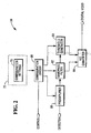
Fig. 2 is a block diagram of an analogue video preprocessing circuit in the optical barcode scanner; and -
Fig. 3 is a flow diagram illustrating the method of configuring video modes. - With reference to
Fig. 1 , an exampleoptical scanner 10 includeslaser 12, mirroredspinner 16,pattern mirrors 18,collector 20,detector 22,video circuitry 28, andcontrol circuitry 32. -
Laser 12 produces a laser beam. - Mirrored
spinner 16 directs the laser beam topattern mirrors 18 and directs light reflected frombar code label 42 tocollector 20. -
Motor 26 rotates mirroredspinner 16. -
Sensor 24 produces a signal for deriving the position of mirroredspinner 16 on its rotational path.Sensor 24 may include a Hall effect device, which produces a fixed number of pulses eachtime motor 26 rotates one revolution.Sensor 24 sends the pulses to controlcircuitry 32. - Patter mirrors 18 direct the laser beam towards
bar code label 42 and direct the reflected light to mirroredspinner 16. -
Collector 20 collects the reflected light and directs it towardsdetector 22. -
Detector 22 converts the reflected light into electrical signals. -
Video circuitry 28 extracts barcode data from the electrical signals.Video circuitry 28 includes analog video pre-processingcircuitry 34 and digitalvideo processing circuitry 36. Exampleoptical scanner 10 includes only one video channel, but the concepts disclose herein may be applied to scanners with more than one video channel. - Analog video pre-processing
circuitry 34 produces analog video signals and sends the signals to digitalvideo processing circuitry 36. - Digital
video processing circuitry 36 extracts barcode data from pre-processed signals. -
Control circuitry 32 controls operation ofscanner 10, decodes barcode data fromvideo circuitry 28, and sends decoded barcode data tocomputer 50.Control circuitry 32 additional changes the operating characteristics of analog video pre-processingcircuitry 34 based upon the position of mirroredspinner 16 andconfiguration settings 70 in memory 72 (Fig. 2 ). - Referring now to
Fig. 2 , analog video pre-processingcircuitry 34 is illustrated in further detail. - Analog video pre-processing
circuitry 34 includespreamplifier 60,bandpass filter 62,threshold generator 64, analog to digital (A/D)converter 66, andconfiguration circuit 68. -
Preamplifier 60 amplifies the output signal fromdetector 22. -
Bandpass filter 62 filters out frequency extremes. -
Threshold generator 64 establishes a comparison threshold level for the filtered analog signal. - Both
bandpass filter 62 andthreshold generator 64 include passive electronic components. Noise coming frompreamplifier 60 must be considered during the design ofbandpass filter 62. Several different discrete component values that characterizebandpass filter 62 andthreshold generator 64 may be empirically determined. - A/
D converter 66 converts the filtered and thresholded analog signal to a digital signal, which is further processed by digitalvideo processing circuitry 36 and ultimately decoded bycontrol circuitry 32. -
Configuration circuit 68 alters operating characteristics of analog video pre-processingcircuitry 34 in response to a control signal fromcontrol circuitry 32. The control signal is based upon spinner position information fromposition sensor 24. In one example mode of operation,configuration circuit 68 changes the operating characteristics with each revolution of mirroredspinner 16. -
Configuration circuit 68 may vary operating characteristics ofbandpass filter 62 and thresholds fromthreshold generator 64 based upon predetermined ranges of barcode densities, contrasts, and print qualities.Configuration settings 70 for different barcode scenarios are stored inmemory 72. -
Configuration circuit 68 automatically cycles through allconfiguration settings 70 during each revolution of mirroredspinner 16, in response to a control signal fromcontrol circuitry 32. Thus,scanner 10 may read a wider range of barcode labels during a single scanning movement. As an additional option,configuration circuit 68 may be programmed via script or otherwise to emphasize configuration settings for more popular barcode densities and print qualities during each cycle. For example,configuration circuit 68 may apply the configuration settings for the more popular barcode densities and print qualities twice as often as less popular barcode densities and print qualities. - With reference to
Fig. 3 , this example embodiment is illustrated in more detail, beginning with START 80. - In step 82,
configuration circuit 68 loads a script intomemory 72 upon bootup, if the script is not already inmemory 72.Configuration circuit 68 may obtain the script from an attached computer, such as a point-of-sale (POS) terminal, throughcontrol circuitry 24. - In step 84,
control circuitry 24 waits for a scanning operation. Operation proceeds to step 86 if a scanning operation has begun. - In step 86,
control circuitry 24 activateslaser 12 andmotor 26, if they are not already activated.Control circuitry 24 may activatelaser 12 andmotor 26 in response to a signal from a sensor in the scanning path. - In step 88,
control circuitry 24 waits for a signal fromspinner position sensor 24. Following receipt of the signal, operation proceeds to step 90. - In step 90,
control circuitry 24 sends an enable signal toconfiguration circuit 68. - In step 92,
configuration circuit 68 readsconfiguration settings 70 frommemory 72 and alters operating characteristics of analog video pre-processingcircuitry 34 in accordance with theconfiguration settings 70. As the script calls fordifferent configuration settings 70,configuration circuit 68 reads the different configuration settings frommemory 72 and executes them. - In step 94,
control circuitry 24 determines whether all scanning operation have finished. If so, operation returns to step 84. Otherwise, operation proceeds to step 88. - This solution offers a cost-effective approach to providing multiple video front ends in
barcode scanner 10. From a performance point of view,barcode scanner 10 can operate on a wider range of barcode densities and print contrast levels. - Although particular reference has been made to certain embodiments, variations and modifications are also envisioned within the scope of the following claims.
Claims (13)
- A barcode scanner comprising:a mirrored spinner (16);a video circuit (34) for detecting and processing light representing a reflection of a laser scan beam from a bar code; characterised in thatsaid barcode scanner comprises a configuration circuit (68) adapted to alter operating characteristics of the video circuit (34) during a scanning operation by cycling the video circuit (34) through a plurality of configuration settings during a single rotation of the mirrored spinner (16) to adapt the video circuit (34) for reading a plurality of different types of barcodes.
- A scanner as claimed in Claim 1, wherein the video circuit (34) comprises a single channel video circuit.
- A scanner as claimed in Claim 1, wherein the configuration circuit (68) executes a script selection among a plurality of different configuration settings of the video circuit (34).
- A scanner as claimed in Claim 1, wherein the video circuit (34) comprises:a bandpass filter (62); anda threshold generator (64);wherein the configuration circuit (68) alters the bandpass filter (62) operating characteristics and threshold generator (64) operating characteristics.
- A scanner as claimed in Claim 4, wherein the configuration circuit (68) executes a script selecting among a plurality of different configuration settings of the bandpass filter (62) and the threshold generator (64).
- A scanner as claimed in any preceding claim, further comprising:a sensor (24) for producing a signal identifying the position of the mirrored spinner (16);wherein the configuration circuit (68) alters the operating characteristics of the video circuit (34) in response to the signal from the sensor (24).
- A scanning method comprisinga) altering the operating characteristics of a video circuit (34) detecting and processing scattered light representing a reflection of laser light scattered from a bar code during a scanning operation by cycling the video circuit (34) through a plurality of configuration settings during a single rotation of a mirrored spinner (16) to adapt the video circuit (34) for reading a plurality of different bar code types; andb) reading any of a plurality of different types of barcode during the scanning operation.
- A method as claimed in Claim 7, wherein step a) comprises:a-1) determining a plurality of different configuration settings of the video circuit (34);a-2) selecting among the configuration settings during the scanning operation; anda-3) implementing selected configuration settings to alter the operating characteristics.
- A method as claimed in Claim 7, wherein step a) comprises:a-1) determining a plurality of different configuration settings of the video circuit (34);a-2) producing a script identifying selected settings of the different configuration settings; anda-3) executing the script to implement the selected settings to alter the operating characteristics.
- A method as claimed in Claim 7, wherein step a) comprises:altering the operating characteristics of a bandpass filter (62) and a threshold generator (64) of the video circuit (34) during a scanning operation.
- A method as claimed in Claim 7, wherein step a) comprises:altering the operating characteristics of the video circuit (34) in response to receiving a signal indicative of a position of a mirrored spinner (16).
- A method as claimed in Claim 8, wherein step a-2) comprises:selecting among the configuration settings in response to receiving a signal indicative of a position of a mirrored spinner (16).
- A method as claimed in Claim 9, wherein step a-3) comprises:executing the script in response to receiving a signal indicative of a position of a mirrored spinner (16).
Applications Claiming Priority (1)
| Application Number | Priority Date | Filing Date | Title |
|---|---|---|---|
| US11/533,905 US7380719B1 (en) | 2006-09-21 | 2006-09-21 | Barcode scanner with configurable video modes |
Publications (2)
| Publication Number | Publication Date |
|---|---|
| EP1903473A1 EP1903473A1 (en) | 2008-03-26 |
| EP1903473B1 true EP1903473B1 (en) | 2011-11-09 |
Family
ID=38910905
Family Applications (1)
| Application Number | Title | Priority Date | Filing Date |
|---|---|---|---|
| EP07253582A Ceased EP1903473B1 (en) | 2006-09-21 | 2007-09-10 | Barcode scanner with configurable video modes |
Country Status (4)
| Country | Link |
|---|---|
| US (1) | US7380719B1 (en) |
| EP (1) | EP1903473B1 (en) |
| JP (1) | JP5283151B2 (en) |
| CN (1) | CN101149786B (en) |
Families Citing this family (2)
| Publication number | Priority date | Publication date | Assignee | Title |
|---|---|---|---|---|
| US8496178B2 (en) * | 2011-08-31 | 2013-07-30 | Ncr Corporation | Method and apparatus for providing customer side imaging as well as bar code scanning imaging |
| US10275624B2 (en) | 2013-10-29 | 2019-04-30 | Hand Held Products, Inc. | Hybrid system and method for reading indicia |
Family Cites Families (18)
| Publication number | Priority date | Publication date | Assignee | Title |
|---|---|---|---|---|
| US5288983A (en) | 1990-06-06 | 1994-02-22 | Sumitomo Electric Industries, Ltd. | Symbol read device having separate gain controls for reading different scan lines |
| JP2794906B2 (en) * | 1990-06-06 | 1998-09-10 | 住友電気工業株式会社 | Symbol reader |
| US6708883B2 (en) * | 1994-06-30 | 2004-03-23 | Symbol Technologies, Inc. | Apparatus and method for reading indicia using charge coupled device and scanning laser beam technology |
| US5949054A (en) * | 1995-10-23 | 1999-09-07 | Welch Allyn, Inc. | Bar code reader for reading high to low contrast bar code symbols |
| US6220513B1 (en) * | 1997-12-31 | 2001-04-24 | Ncr Corporation | Methods and apparatus for determining bar code label location information |
| US6394351B1 (en) * | 1997-12-31 | 2002-05-28 | Ncr Corporation | Methods and apparatus for enhanced scanner operation employing bar code and bar code fragment time and position of data collection |
| US6497366B1 (en) * | 1997-12-31 | 2002-12-24 | Ncr Corporation | Methods and apparatus for dual channel video recovery in bar code scanners |
| US6293468B1 (en) * | 1998-11-02 | 2001-09-25 | Ncr Corporation | Pulsed barcode scanner |
| JP4197812B2 (en) * | 1999-10-27 | 2008-12-17 | オリンパス株式会社 | Code information reader |
| US6726094B1 (en) * | 2000-01-19 | 2004-04-27 | Ncr Corporation | Method and apparatus for multiple format image capture for use in retail transactions |
| WO2001082214A1 (en) | 2000-02-28 | 2001-11-01 | Psc Scanning, Inc. | Multi-format bar code reader |
| JP3546813B2 (en) * | 2000-06-15 | 2004-07-28 | 日本電気株式会社 | Barcode reader |
| ES2272433T3 (en) * | 2001-10-05 | 2007-05-01 | Datalogic S.P.A. | OPTICAL READING DEVICE. |
| EP1519295A4 (en) * | 2002-06-28 | 2010-01-20 | Fujitsu Ltd | READER AND PROGRAM FOR READING BAR CODE |
| US7044382B2 (en) | 2002-06-28 | 2006-05-16 | Fujitsu Limited | Bar-code reader and computer product |
| JP4059173B2 (en) * | 2003-06-27 | 2008-03-12 | 株式会社デンソーウェーブ | Optical information reading apparatus and optical information reading method |
| US6874688B1 (en) * | 2004-03-22 | 2005-04-05 | Symbol Technologies, Inc. | Data collection signal processing for increased performance in electro-optical readers |
| US7178732B1 (en) * | 2004-11-08 | 2007-02-20 | Ncr Corporation | Bar code reader with image display system |
-
2006
- 2006-09-21 US US11/533,905 patent/US7380719B1/en not_active Expired - Fee Related
-
2007
- 2007-09-10 EP EP07253582A patent/EP1903473B1/en not_active Ceased
- 2007-09-13 JP JP2007237424A patent/JP5283151B2/en not_active Expired - Fee Related
- 2007-09-13 CN CN200710154076XA patent/CN101149786B/en not_active Expired - Fee Related
Also Published As
| Publication number | Publication date |
|---|---|
| CN101149786A (en) | 2008-03-26 |
| US7380719B1 (en) | 2008-06-03 |
| US20080121717A1 (en) | 2008-05-29 |
| JP2008077653A (en) | 2008-04-03 |
| CN101149786B (en) | 2011-08-17 |
| EP1903473A1 (en) | 2008-03-26 |
| JP5283151B2 (en) | 2013-09-04 |
Similar Documents
| Publication | Publication Date | Title |
|---|---|---|
| CN102622569B (en) | Barcode Reader with Enhanced Edge Detection | |
| US5278397A (en) | Multi-resolution bar code reader | |
| US6176429B1 (en) | Optical reader with selectable processing characteristics for reading data in multiple formats | |
| US6213399B1 (en) | Multi-channel signal processing in an optical reader | |
| US7527203B2 (en) | Multi-format bar code reader | |
| US6073849A (en) | Electronic edge detection system using a second derivative signal processor | |
| EP1903473B1 (en) | Barcode scanner with configurable video modes | |
| EP2182467B1 (en) | Method and apparatus for optically reading out information stored in a barcode | |
| EP0927946B1 (en) | Methods and apparatus for dual channel video recovery in bar code scanners | |
| AU2005226045B2 (en) | Data collection signal processing for increased performance in electro-optical readers | |
| US5811777A (en) | Method and apparatus for utilizing specular light to image low contrast symbols | |
| CN205959208U (en) | Scanner | |
| US7628331B2 (en) | Method and system for optimizing scanner performance | |
| US7562826B2 (en) | Scan engine with dual chip architecture for use in electro-optical readers | |
| EP0936572B1 (en) | Optical device for reading and decoding a barcode | |
| EP3232367A1 (en) | Imaging barcode reader with color separated aimer and illuminator | |
| JP2738108B2 (en) | Barcode reader | |
| EP1261934A1 (en) | Multi-format bar code reader | |
| JP2010097317A (en) | Bar code reading method and bar code reading device | |
| JPH04216184A (en) | Bar code reader | |
| CN107301359A (en) | Imaging Barcode Reader with Color-Separated Aimer and Illuminator | |
| JPH06231290A (en) | Device for shaping light receiving signal for bar code reader | |
| JPH0668776B2 (en) | Optical information reader | |
| JPH08292995A (en) | Optical reader |
Legal Events
| Date | Code | Title | Description |
|---|---|---|---|
| PUAI | Public reference made under article 153(3) epc to a published international application that has entered the european phase |
Free format text: ORIGINAL CODE: 0009012 |
|
| AK | Designated contracting states |
Kind code of ref document: A1 Designated state(s): AT BE BG CH CY CZ DE DK EE ES FI FR GB GR HU IE IS IT LI LT LU LV MC MT NL PL PT RO SE SI SK TR |
|
| AX | Request for extension of the european patent |
Extension state: AL BA HR MK YU |
|
| 17P | Request for examination filed |
Effective date: 20080926 |
|
| 17Q | First examination report despatched |
Effective date: 20081028 |
|
| AKX | Designation fees paid |
Designated state(s): DE FR GB |
|
| RAP1 | Party data changed (applicant data changed or rights of an application transferred) |
Owner name: NCR CORPORATION |
|
| GRAP | Despatch of communication of intention to grant a patent |
Free format text: ORIGINAL CODE: EPIDOSNIGR1 |
|
| GRAS | Grant fee paid |
Free format text: ORIGINAL CODE: EPIDOSNIGR3 |
|
| GRAA | (expected) grant |
Free format text: ORIGINAL CODE: 0009210 |
|
| AK | Designated contracting states |
Kind code of ref document: B1 Designated state(s): DE FR GB |
|
| REG | Reference to a national code |
Ref country code: GB Ref legal event code: FG4D |
|
| REG | Reference to a national code |
Ref country code: GB Ref legal event code: 746 Effective date: 20111105 |
|
| REG | Reference to a national code |
Ref country code: DE Ref legal event code: R096 Ref document number: 602007018582 Country of ref document: DE Effective date: 20120119 Ref country code: DE Ref legal event code: R084 Ref document number: 602007018582 Country of ref document: DE Effective date: 20111123 |
|
| PLBE | No opposition filed within time limit |
Free format text: ORIGINAL CODE: 0009261 |
|
| STAA | Information on the status of an ep patent application or granted ep patent |
Free format text: STATUS: NO OPPOSITION FILED WITHIN TIME LIMIT |
|
| 26N | No opposition filed |
Effective date: 20120810 |
|
| REG | Reference to a national code |
Ref country code: DE Ref legal event code: R097 Ref document number: 602007018582 Country of ref document: DE Effective date: 20120810 |
|
| REG | Reference to a national code |
Ref country code: FR Ref legal event code: PLFP Year of fee payment: 10 |
|
| REG | Reference to a national code |
Ref country code: FR Ref legal event code: PLFP Year of fee payment: 11 |
|
| REG | Reference to a national code |
Ref country code: FR Ref legal event code: PLFP Year of fee payment: 12 |
|
| PGFP | Annual fee paid to national office [announced via postgrant information from national office to epo] |
Ref country code: DE Payment date: 20180927 Year of fee payment: 12 Ref country code: FR Payment date: 20180925 Year of fee payment: 12 |
|
| PGFP | Annual fee paid to national office [announced via postgrant information from national office to epo] |
Ref country code: GB Payment date: 20180927 Year of fee payment: 12 |
|
| REG | Reference to a national code |
Ref country code: DE Ref legal event code: R081 Ref document number: 602007018582 Country of ref document: DE Owner name: NCR CORPORATION, ATLANTA, US Free format text: FORMER OWNER: NCR CORP., DULUTH, GA., US |
|
| REG | Reference to a national code |
Ref country code: DE Ref legal event code: R119 Ref document number: 602007018582 Country of ref document: DE |
|
| PG25 | Lapsed in a contracting state [announced via postgrant information from national office to epo] |
Ref country code: DE Free format text: LAPSE BECAUSE OF NON-PAYMENT OF DUE FEES Effective date: 20200401 |
|
| GBPC | Gb: european patent ceased through non-payment of renewal fee |
Effective date: 20190910 |
|
| PG25 | Lapsed in a contracting state [announced via postgrant information from national office to epo] |
Ref country code: GB Free format text: LAPSE BECAUSE OF NON-PAYMENT OF DUE FEES Effective date: 20190910 Ref country code: FR Free format text: LAPSE BECAUSE OF NON-PAYMENT OF DUE FEES Effective date: 20190930 |