EP1903473B1 - Lecteur de codes barres avec des modes vidéo configurables - Google Patents
Lecteur de codes barres avec des modes vidéo configurables Download PDFInfo
- Publication number
- EP1903473B1 EP1903473B1 EP07253582A EP07253582A EP1903473B1 EP 1903473 B1 EP1903473 B1 EP 1903473B1 EP 07253582 A EP07253582 A EP 07253582A EP 07253582 A EP07253582 A EP 07253582A EP 1903473 B1 EP1903473 B1 EP 1903473B1
- Authority
- EP
- European Patent Office
- Prior art keywords
- video circuit
- circuit
- operating characteristics
- configuration settings
- scanner
- Prior art date
- Legal status (The legal status is an assumption and is not a legal conclusion. Google has not performed a legal analysis and makes no representation as to the accuracy of the status listed.)
- Ceased
Links
Images


Classifications
-
- G—PHYSICS
- G06—COMPUTING OR CALCULATING; COUNTING
- G06K—GRAPHICAL DATA READING; PRESENTATION OF DATA; RECORD CARRIERS; HANDLING RECORD CARRIERS
- G06K7/00—Methods or arrangements for sensing record carriers, e.g. for reading patterns
- G06K7/10—Methods or arrangements for sensing record carriers, e.g. for reading patterns by electromagnetic radiation, e.g. optical sensing; by corpuscular radiation
- G06K7/10544—Methods or arrangements for sensing record carriers, e.g. for reading patterns by electromagnetic radiation, e.g. optical sensing; by corpuscular radiation by scanning of the records by radiation in the optical part of the electromagnetic spectrum
- G06K7/10821—Methods or arrangements for sensing record carriers, e.g. for reading patterns by electromagnetic radiation, e.g. optical sensing; by corpuscular radiation by scanning of the records by radiation in the optical part of the electromagnetic spectrum further details of bar or optical code scanning devices
- G06K7/10851—Circuits for pulse shaping, amplifying, eliminating noise signals, checking the function of the sensing device
Definitions
- the video front end circuitry of a barcode scanner is tuned to respond to less than perfect signals coming from the laser spot crossing over a barcode label.
- Barcode label characteristics can vary. For example, barcode density or frequency and print quality may vary. Print quality is affected by overprinting or underprinting, speckles between transitions which create noise, and print intensity or contrast.
- a barcode scanner might have several channels where the video circuit in each channel is tuned to optimise the reading with regard to any of the variables previously mentioned.
- the US patent application published as US 2005/150958 and forming the preamble of claim 1, the International patent application published as WO 01/82214 and US patent no. US 5,288,983 disclose parameter optimisation in barcode scanners. Less expensive barcode scanners with fewer or only one video channel cannot be easily optimised to read different types of barcodes. A barcode scanner with only one video channel has a static circuit which cannot be optimised to read all barcodes that vary widely.
- a barcode scanner with configurable video modes is provided.
- an example optical scanner 10 includes laser 12, mirrored spinner 16, pattern mirrors 18, collector 20, detector 22, video circuitry 28, and control circuitry 32.
- Laser 12 produces a laser beam.
- Mirrored spinner 16 directs the laser beam to pattern mirrors 18 and directs light reflected from bar code label 42 to collector 20.
- Motor 26 rotates mirrored spinner 16.
- Sensor 24 produces a signal for deriving the position of mirrored spinner 16 on its rotational path.
- Sensor 24 may include a Hall effect device, which produces a fixed number of pulses each time motor 26 rotates one revolution. Sensor 24 sends the pulses to control circuitry 32.
- Patter mirrors 18 direct the laser beam towards bar code label 42 and direct the reflected light to mirrored spinner 16.
- Collector 20 collects the reflected light and directs it towards detector 22.
- Detector 22 converts the reflected light into electrical signals.
- Video circuitry 28 extracts barcode data from the electrical signals.
- Video circuitry 28 includes analog video pre-processing circuitry 34 and digital video processing circuitry 36.
- Example optical scanner 10 includes only one video channel, but the concepts disclose herein may be applied to scanners with more than one video channel.
- Analog video pre-processing circuitry 34 produces analog video signals and sends the signals to digital video processing circuitry 36.
- Digital video processing circuitry 36 extracts barcode data from pre-processed signals.
- Control circuitry 32 controls operation of scanner 10, decodes barcode data from video circuitry 28, and sends decoded barcode data to computer 50. Control circuitry 32 additional changes the operating characteristics of analog video pre-processing circuitry 34 based upon the position of mirrored spinner 16 and configuration settings 70 in memory 72 ( Fig. 2 ).
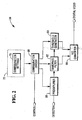
- analog video pre-processing circuitry 34 is illustrated in further detail.
- Analog video pre-processing circuitry 34 includes preamplifier 60, bandpass filter 62, threshold generator 64, analog to digital (A/D) converter 66, and configuration circuit 68.
- Preamplifier 60 amplifies the output signal from detector 22.
- Bandpass filter 62 filters out frequency extremes.
- Threshold generator 64 establishes a comparison threshold level for the filtered analog signal.
- Both bandpass filter 62 and threshold generator 64 include passive electronic components. Noise coming from preamplifier 60 must be considered during the design of bandpass filter 62. Several different discrete component values that characterize bandpass filter 62 and threshold generator 64 may be empirically determined.
- A/D converter 66 converts the filtered and thresholded analog signal to a digital signal, which is further processed by digital video processing circuitry 36 and ultimately decoded by control circuitry 32.
- Configuration circuit 68 alters operating characteristics of analog video pre-processing circuitry 34 in response to a control signal from control circuitry 32.
- the control signal is based upon spinner position information from position sensor 24.
- configuration circuit 68 changes the operating characteristics with each revolution of mirrored spinner 16.
- Configuration circuit 68 may vary operating characteristics of bandpass filter 62 and thresholds from threshold generator 64 based upon predetermined ranges of barcode densities, contrasts, and print qualities. Configuration settings 70 for different barcode scenarios are stored in memory 72.
- Configuration circuit 68 automatically cycles through all configuration settings 70 during each revolution of mirrored spinner 16, in response to a control signal from control circuitry 32. Thus, scanner 10 may read a wider range of barcode labels during a single scanning movement.
- configuration circuit 68 may be programmed via script or otherwise to emphasize configuration settings for more popular barcode densities and print qualities during each cycle. For example, configuration circuit 68 may apply the configuration settings for the more popular barcode densities and print qualities twice as often as less popular barcode densities and print qualities.
- configuration circuit 68 loads a script into memory 72 upon bootup, if the script is not already in memory 72.
- Configuration circuit 68 may obtain the script from an attached computer, such as a point-of-sale (POS) terminal, through control circuitry 24.
- POS point-of-sale
- control circuitry 24 waits for a scanning operation. Operation proceeds to step 86 if a scanning operation has begun.
- control circuitry 24 activates laser 12 and motor 26, if they are not already activated.
- Control circuitry 24 may activate laser 12 and motor 26 in response to a signal from a sensor in the scanning path.
- control circuitry 24 waits for a signal from spinner position sensor 24. Following receipt of the signal, operation proceeds to step 90.
- control circuitry 24 sends an enable signal to configuration circuit 68.
- step 92 configuration circuit 68 reads configuration settings 70 from memory 72 and alters operating characteristics of analog video pre-processing circuitry 34 in accordance with the configuration settings 70. As the script calls for different configuration settings 70, configuration circuit 68 reads the different configuration settings from memory 72 and executes them.
- control circuitry 24 determines whether all scanning operation have finished. If so, operation returns to step 84. Otherwise, operation proceeds to step 88.
- barcode scanner 10 can operate on a wider range of barcode densities and print contrast levels.
Landscapes
- Physics & Mathematics (AREA)
- Electromagnetism (AREA)
- Engineering & Computer Science (AREA)
- Health & Medical Sciences (AREA)
- General Health & Medical Sciences (AREA)
- Toxicology (AREA)
- Artificial Intelligence (AREA)
- Computer Vision & Pattern Recognition (AREA)
- General Physics & Mathematics (AREA)
- Theoretical Computer Science (AREA)
- Facsimile Scanning Arrangements (AREA)
Claims (13)
- Lecteur de codes barres comprenant :une tournette (16) rendue réfléchissante ;un circuit (34) vidéo pour détecter et traiter de la lumière représentant une réflexion d'un faisceau laser de lecture provenant d'un codes barres ; caractérisé en quele lecteur de codes barres comprend un circuit (68) de configuration, conçu pour modifier des caractéristiques de fonctionnement du circuit (34) vidéo pendant une opération de lecture, en cyclant le circuit (34) vidéo par une pluralité de réglages de configuration pendant une seule rotation de la tournette (16) rendue réfléchissante, pour adapter le circuit (34) vidéo en vue de lire une pluralité de types différents de codes barres.
- Lecteur suivant la revendication 1, dans lequel le circuit (34) vidéo comprend un circuit vidéo monocanal.
- Lecteur suivant la revendication 1, dans lequel le circuit (68) de configuration exécute une sélection de scénario parmi une pluralité de réglages différents de configuration du circuit (34) vidéo.
- Lecteur suivant la revendication 1, dans lequel le circuit (34) vidéo comprend :un filtre (62) passe bande ; etun générateur (64) de seuil ;dans lequel le circuit (68) de configuration modifie les caractéristiques de fonctionnement du filtre (62) passe bande et les caractéristiques de fonctionnement du générateur (64) de seuil.
- Lecteur suivant la revendication 4, dans lequel le circuit de configuration exécute un scénario sélectionnant parmi une pluralité de réglages différents de configuration du filtre (62) passe bande et du générateur (64) de seuil.
- Lecteur suivant l'une quelconque des revendications précédentes, comprenant en outre :un capteur (24) de production d'un signal identifiant la position de la tournette (16) rendue réfléchissante ;dans lequel le circuit (68) de configuration modifie les caractéristiques de fonctionnement du circuit (34) vidéo en réaction au signal provenant du capteur (24).
- Procédé de lecture comprenanta) la modification des caractéristiques de fonctionnement d'un circuit (34) vidéo détectant et traitant de la lumière dispersée représentant une réflexion d'une lumière laser dispersée par un codes barres pendant une opération de lecture, en cyclant le circuit (34) vidéo par une pluralité de réglages de configuration pendant une seule rotation d'une tournette (16) rendue réfléchissante, pour adapter le circuit (34) vidéo afin de lire une pluralité de types différents de codes barres ;b) la lecture d'un type quelconque d'une pluralité de types différents de codes barres pendant l'opération de lecture.
- Procédé suivant la revendication 7, dans lequel le stade a) comprend :a-1) la détermination d'une pluralité de réglages différents de configuration du circuit (34) vidéo ;a-2) la sélection parmi les réglages de configuration pendant l'opération de lecture ; eta-3) la mise en oeuvre de réglage sélectionné de configuration pour modifier les caractéristiques de fonctionnement.
- Procédé suivant la revendication 7, dans lequel le stade a) comprend :a-1) la détermination d'une pluralité de réglages différents de configuration du circuit (34) vidéo ;a-2) la production d'un scénario identifiant des réglages sélectionnés parmi les réglages différents de configuration ;a-3) l'exécution du scénario pour mettre en oeuvre les réglages sélectionnés pour modifier les caractéristiques de fonctionnement.
- Procédé suivant la revendication 7, dans lequel le stade a) comprend :la modification des caractéristiques de fonctionnement d'un filtre (62) passe bande et d'un générateur (64) de seuil du circuit (34) vidéo pendant une opération de balayage.
- Procédé suivant la revendication 7, dans lequel le stade a) comprend :la modification des caractéristiques de fonctionnement du circuit (34) vidéo en réaction à la réception d'un signal indiquant une position d'une tournette (16) rendue réfléchissante.
- Procédé suivant la revendication 8, dans lequel le stade a-2) comprend :la sélection parmi les réglages de configuration en réaction à la réception d'un signal indiquant une position d'une tournette (16) rendue réfléchissante.
- Procédé suivant la revendication 9, dans lequel le stade a-3) comprend :l'exécution du scénario en réaction à la réception d'un signal indiquant une position d'une tournette (16) rendue réfléchissante.
Applications Claiming Priority (1)
| Application Number | Priority Date | Filing Date | Title |
|---|---|---|---|
| US11/533,905 US7380719B1 (en) | 2006-09-21 | 2006-09-21 | Barcode scanner with configurable video modes |
Publications (2)
| Publication Number | Publication Date |
|---|---|
| EP1903473A1 EP1903473A1 (fr) | 2008-03-26 |
| EP1903473B1 true EP1903473B1 (fr) | 2011-11-09 |
Family
ID=38910905
Family Applications (1)
| Application Number | Title | Priority Date | Filing Date |
|---|---|---|---|
| EP07253582A Ceased EP1903473B1 (fr) | 2006-09-21 | 2007-09-10 | Lecteur de codes barres avec des modes vidéo configurables |
Country Status (4)
| Country | Link |
|---|---|
| US (1) | US7380719B1 (fr) |
| EP (1) | EP1903473B1 (fr) |
| JP (1) | JP5283151B2 (fr) |
| CN (1) | CN101149786B (fr) |
Families Citing this family (2)
| Publication number | Priority date | Publication date | Assignee | Title |
|---|---|---|---|---|
| US8496178B2 (en) * | 2011-08-31 | 2013-07-30 | Ncr Corporation | Method and apparatus for providing customer side imaging as well as bar code scanning imaging |
| US10275624B2 (en) | 2013-10-29 | 2019-04-30 | Hand Held Products, Inc. | Hybrid system and method for reading indicia |
Family Cites Families (18)
| Publication number | Priority date | Publication date | Assignee | Title |
|---|---|---|---|---|
| US5288983A (en) | 1990-06-06 | 1994-02-22 | Sumitomo Electric Industries, Ltd. | Symbol read device having separate gain controls for reading different scan lines |
| JP2794906B2 (ja) * | 1990-06-06 | 1998-09-10 | 住友電気工業株式会社 | 記号読取装置 |
| US6708883B2 (en) * | 1994-06-30 | 2004-03-23 | Symbol Technologies, Inc. | Apparatus and method for reading indicia using charge coupled device and scanning laser beam technology |
| US5949054A (en) * | 1995-10-23 | 1999-09-07 | Welch Allyn, Inc. | Bar code reader for reading high to low contrast bar code symbols |
| US6220513B1 (en) * | 1997-12-31 | 2001-04-24 | Ncr Corporation | Methods and apparatus for determining bar code label location information |
| US6394351B1 (en) * | 1997-12-31 | 2002-05-28 | Ncr Corporation | Methods and apparatus for enhanced scanner operation employing bar code and bar code fragment time and position of data collection |
| US6497366B1 (en) * | 1997-12-31 | 2002-12-24 | Ncr Corporation | Methods and apparatus for dual channel video recovery in bar code scanners |
| US6293468B1 (en) * | 1998-11-02 | 2001-09-25 | Ncr Corporation | Pulsed barcode scanner |
| JP4197812B2 (ja) * | 1999-10-27 | 2008-12-17 | オリンパス株式会社 | 符号情報読取装置 |
| US6726094B1 (en) * | 2000-01-19 | 2004-04-27 | Ncr Corporation | Method and apparatus for multiple format image capture for use in retail transactions |
| WO2001082214A1 (fr) | 2000-02-28 | 2001-11-01 | Psc Scanning, Inc. | Lecteur de code-barres a formats multiples |
| JP3546813B2 (ja) * | 2000-06-15 | 2004-07-28 | 日本電気株式会社 | バーコード読取装置 |
| ES2272433T3 (es) * | 2001-10-05 | 2007-05-01 | Datalogic S.P.A. | Aparato de lectura optica. |
| EP1519295A4 (fr) * | 2002-06-28 | 2010-01-20 | Fujitsu Ltd | Lecteur et programme de lecture de code a barres |
| US7044382B2 (en) | 2002-06-28 | 2006-05-16 | Fujitsu Limited | Bar-code reader and computer product |
| JP4059173B2 (ja) * | 2003-06-27 | 2008-03-12 | 株式会社デンソーウェーブ | 光学的情報読取装置および光学的情報の読取方法 |
| US6874688B1 (en) * | 2004-03-22 | 2005-04-05 | Symbol Technologies, Inc. | Data collection signal processing for increased performance in electro-optical readers |
| US7178732B1 (en) * | 2004-11-08 | 2007-02-20 | Ncr Corporation | Bar code reader with image display system |
-
2006
- 2006-09-21 US US11/533,905 patent/US7380719B1/en not_active Expired - Fee Related
-
2007
- 2007-09-10 EP EP07253582A patent/EP1903473B1/fr not_active Ceased
- 2007-09-13 JP JP2007237424A patent/JP5283151B2/ja not_active Expired - Fee Related
- 2007-09-13 CN CN200710154076XA patent/CN101149786B/zh not_active Expired - Fee Related
Also Published As
| Publication number | Publication date |
|---|---|
| CN101149786A (zh) | 2008-03-26 |
| US7380719B1 (en) | 2008-06-03 |
| US20080121717A1 (en) | 2008-05-29 |
| JP2008077653A (ja) | 2008-04-03 |
| CN101149786B (zh) | 2011-08-17 |
| EP1903473A1 (fr) | 2008-03-26 |
| JP5283151B2 (ja) | 2013-09-04 |
Similar Documents
| Publication | Publication Date | Title |
|---|---|---|
| CN102622569B (zh) | 具有边缘检测增强的条码读取器 | |
| US5278397A (en) | Multi-resolution bar code reader | |
| US6176429B1 (en) | Optical reader with selectable processing characteristics for reading data in multiple formats | |
| US6213399B1 (en) | Multi-channel signal processing in an optical reader | |
| US7527203B2 (en) | Multi-format bar code reader | |
| US6073849A (en) | Electronic edge detection system using a second derivative signal processor | |
| EP1903473B1 (fr) | Lecteur de codes barres avec des modes vidéo configurables | |
| EP2182467B1 (fr) | Procédé et appareil pour la lecture optique d'informations stockées dans un code-barres | |
| EP0927946B1 (fr) | Appareil et procédé pour récupération d'un signal video à deux caneaux dans des lecteurs de codes à barres | |
| AU2005226045B2 (en) | Data collection signal processing for increased performance in electro-optical readers | |
| US5811777A (en) | Method and apparatus for utilizing specular light to image low contrast symbols | |
| CN205959208U (zh) | 一种扫描器 | |
| US7628331B2 (en) | Method and system for optimizing scanner performance | |
| US7562826B2 (en) | Scan engine with dual chip architecture for use in electro-optical readers | |
| EP0936572B1 (fr) | Dispositif optique de lecture et de décodage d'un code à barres | |
| EP3232367A1 (fr) | Lecteur de code à barres par imagerie avec viseur à séparation des couleurs et illuminateur | |
| JP2738108B2 (ja) | バーコード読取装置 | |
| EP1261934A1 (fr) | Lecteur de code-barres a formats multiples | |
| JP2010097317A (ja) | バーコード読取方法およびバーコード読取装置 | |
| JPH04216184A (ja) | バーコード読取装置 | |
| CN107301359A (zh) | 具有颜色分离的瞄准器和照明器的成像条形码阅读器 | |
| JPH06231290A (ja) | バーコード読取装置の受光信号整形装置 | |
| JPH0668776B2 (ja) | 光学的情報読取装置 | |
| JPH08292995A (ja) | 光学式読取装置 |
Legal Events
| Date | Code | Title | Description |
|---|---|---|---|
| PUAI | Public reference made under article 153(3) epc to a published international application that has entered the european phase |
Free format text: ORIGINAL CODE: 0009012 |
|
| AK | Designated contracting states |
Kind code of ref document: A1 Designated state(s): AT BE BG CH CY CZ DE DK EE ES FI FR GB GR HU IE IS IT LI LT LU LV MC MT NL PL PT RO SE SI SK TR |
|
| AX | Request for extension of the european patent |
Extension state: AL BA HR MK YU |
|
| 17P | Request for examination filed |
Effective date: 20080926 |
|
| 17Q | First examination report despatched |
Effective date: 20081028 |
|
| AKX | Designation fees paid |
Designated state(s): DE FR GB |
|
| RAP1 | Party data changed (applicant data changed or rights of an application transferred) |
Owner name: NCR CORPORATION |
|
| GRAP | Despatch of communication of intention to grant a patent |
Free format text: ORIGINAL CODE: EPIDOSNIGR1 |
|
| GRAS | Grant fee paid |
Free format text: ORIGINAL CODE: EPIDOSNIGR3 |
|
| GRAA | (expected) grant |
Free format text: ORIGINAL CODE: 0009210 |
|
| AK | Designated contracting states |
Kind code of ref document: B1 Designated state(s): DE FR GB |
|
| REG | Reference to a national code |
Ref country code: GB Ref legal event code: FG4D |
|
| REG | Reference to a national code |
Ref country code: GB Ref legal event code: 746 Effective date: 20111105 |
|
| REG | Reference to a national code |
Ref country code: DE Ref legal event code: R096 Ref document number: 602007018582 Country of ref document: DE Effective date: 20120119 Ref country code: DE Ref legal event code: R084 Ref document number: 602007018582 Country of ref document: DE Effective date: 20111123 |
|
| PLBE | No opposition filed within time limit |
Free format text: ORIGINAL CODE: 0009261 |
|
| STAA | Information on the status of an ep patent application or granted ep patent |
Free format text: STATUS: NO OPPOSITION FILED WITHIN TIME LIMIT |
|
| 26N | No opposition filed |
Effective date: 20120810 |
|
| REG | Reference to a national code |
Ref country code: DE Ref legal event code: R097 Ref document number: 602007018582 Country of ref document: DE Effective date: 20120810 |
|
| REG | Reference to a national code |
Ref country code: FR Ref legal event code: PLFP Year of fee payment: 10 |
|
| REG | Reference to a national code |
Ref country code: FR Ref legal event code: PLFP Year of fee payment: 11 |
|
| REG | Reference to a national code |
Ref country code: FR Ref legal event code: PLFP Year of fee payment: 12 |
|
| PGFP | Annual fee paid to national office [announced via postgrant information from national office to epo] |
Ref country code: DE Payment date: 20180927 Year of fee payment: 12 Ref country code: FR Payment date: 20180925 Year of fee payment: 12 |
|
| PGFP | Annual fee paid to national office [announced via postgrant information from national office to epo] |
Ref country code: GB Payment date: 20180927 Year of fee payment: 12 |
|
| REG | Reference to a national code |
Ref country code: DE Ref legal event code: R081 Ref document number: 602007018582 Country of ref document: DE Owner name: NCR CORPORATION, ATLANTA, US Free format text: FORMER OWNER: NCR CORP., DULUTH, GA., US |
|
| REG | Reference to a national code |
Ref country code: DE Ref legal event code: R119 Ref document number: 602007018582 Country of ref document: DE |
|
| PG25 | Lapsed in a contracting state [announced via postgrant information from national office to epo] |
Ref country code: DE Free format text: LAPSE BECAUSE OF NON-PAYMENT OF DUE FEES Effective date: 20200401 |
|
| GBPC | Gb: european patent ceased through non-payment of renewal fee |
Effective date: 20190910 |
|
| PG25 | Lapsed in a contracting state [announced via postgrant information from national office to epo] |
Ref country code: GB Free format text: LAPSE BECAUSE OF NON-PAYMENT OF DUE FEES Effective date: 20190910 Ref country code: FR Free format text: LAPSE BECAUSE OF NON-PAYMENT OF DUE FEES Effective date: 20190930 |