EP1903562A2 - Verfahren zum Aufzeichnen/Zeichnen auf einer optischen Platte - Google Patents
Verfahren zum Aufzeichnen/Zeichnen auf einer optischen Platte Download PDFInfo
- Publication number
- EP1903562A2 EP1903562A2 EP07018818A EP07018818A EP1903562A2 EP 1903562 A2 EP1903562 A2 EP 1903562A2 EP 07018818 A EP07018818 A EP 07018818A EP 07018818 A EP07018818 A EP 07018818A EP 1903562 A2 EP1903562 A2 EP 1903562A2
- Authority
- EP
- European Patent Office
- Prior art keywords
- recording
- image drawing
- image
- data
- optical disk
- Prior art date
- Legal status (The legal status is an assumption and is not a legal conclusion. Google has not performed a legal analysis and makes no representation as to the accuracy of the status listed.)
- Withdrawn
Links
- 230000003287 optical effect Effects 0.000 title claims description 109
- 238000000034 method Methods 0.000 title claims description 19
- 239000010410 layer Substances 0.000 description 79
- 238000005070 sampling Methods 0.000 description 23
- 238000010586 diagram Methods 0.000 description 13
- 239000011295 pitch Substances 0.000 description 8
- 230000001360 synchronised effect Effects 0.000 description 8
- 230000004044 response Effects 0.000 description 7
- 238000011112 process operation Methods 0.000 description 5
- 230000006870 function Effects 0.000 description 4
- 230000002093 peripheral effect Effects 0.000 description 4
- 229920000515 polycarbonate Polymers 0.000 description 4
- 239000004417 polycarbonate Substances 0.000 description 4
- 241001025261 Neoraja caerulea Species 0.000 description 2
- 230000003247 decreasing effect Effects 0.000 description 2
- 239000000463 material Substances 0.000 description 2
- 230000000630 rising effect Effects 0.000 description 2
- 230000002123 temporal effect Effects 0.000 description 2
- 239000012790 adhesive layer Substances 0.000 description 1
- 201000009310 astigmatism Diseases 0.000 description 1
- 239000013078 crystal Substances 0.000 description 1
- 230000003111 delayed effect Effects 0.000 description 1
- 238000012986 modification Methods 0.000 description 1
Images








Classifications
-
- G—PHYSICS
- G11—INFORMATION STORAGE
- G11B—INFORMATION STORAGE BASED ON RELATIVE MOVEMENT BETWEEN RECORD CARRIER AND TRANSDUCER
- G11B7/00—Recording or reproducing by optical means, e.g. recording using a thermal beam of optical radiation by modifying optical properties or the physical structure, reproducing using an optical beam at lower power by sensing optical properties; Record carriers therefor
- G11B7/002—Recording, reproducing or erasing systems characterised by the shape or form of the carrier
- G11B7/0037—Recording, reproducing or erasing systems characterised by the shape or form of the carrier with discs
-
- G—PHYSICS
- G11—INFORMATION STORAGE
- G11B—INFORMATION STORAGE BASED ON RELATIVE MOVEMENT BETWEEN RECORD CARRIER AND TRANSDUCER
- G11B7/00—Recording or reproducing by optical means, e.g. recording using a thermal beam of optical radiation by modifying optical properties or the physical structure, reproducing using an optical beam at lower power by sensing optical properties; Record carriers therefor
- G11B7/12—Heads, e.g. forming of the optical beam spot or modulation of the optical beam
- G11B7/125—Optical beam sources therefor, e.g. laser control circuitry specially adapted for optical storage devices; Modulators, e.g. means for controlling the size or intensity of optical spots or optical traces
- G11B7/126—Circuits, methods or arrangements for laser control or stabilisation
- G11B7/1263—Power control during transducing, e.g. by monitoring
-
- G—PHYSICS
- G11—INFORMATION STORAGE
- G11B—INFORMATION STORAGE BASED ON RELATIVE MOVEMENT BETWEEN RECORD CARRIER AND TRANSDUCER
- G11B7/00—Recording or reproducing by optical means, e.g. recording using a thermal beam of optical radiation by modifying optical properties or the physical structure, reproducing using an optical beam at lower power by sensing optical properties; Record carriers therefor
- G11B7/24—Record carriers characterised by shape, structure or physical properties, or by the selection of the material
- G11B7/2403—Layers; Shape, structure or physical properties thereof
- G11B7/24035—Recording layers
- G11B7/24038—Multiple laminated recording layers
Definitions
- the present invention is related to a method for applying two optical beams from an objective lens of a single optical pickup to an optical disk where a data recording layer and an image drawing layer are superimposed with each other so that data is recorded on the data recording layer by one of the optical beams and an image is drawn (forming of visible image) on the image drawing layer by the other beam (will be referred to as "simultaneous recording/drawing" hereinafter).
- a data recording layer and an image drawing layer are superimposed with each other so that data is recorded on the data recording layer by one of the optical beams and an image is drawn (forming of visible image) on the image drawing layer by the other beam
- optical disk recording/drawing technique is described in JP-A-2005-346886 . That is, an image drawing layer made of a thermal sensitive layer, a photosensitive layer, and the like is formed on a disk surface of such an optical disk as a recordable CD media and a recordable DVD media.
- An optical disk recording apparatus for recording data on a data recording layer of the above optical disk is commonly operated as an optical disk drawing apparatus so as to irradiate laser beam modulated in response to image data from an optical pickup onto the image drawing layer, so that an image is drawn on the image drawing layer.
- two laser beams are emitted from a single optical pickup in a coaxial manner, one of these two laser beams is irradiated onto the data recording layer, and both a focusing control operation and a tracking control operation are carried out for the one so as to record data on the data recording layer, whereas the other laser beam is irradiated onto a predetermined position of the image drawing layer so as to draw an image thereon (namely, "simultaneous recording/image drawing" is carried out) in parallel to the data recording operation.
- the image drawing operation is carried out by the other optical beam at the same time.
- temperatures as to laser diodes and laser drivers of the optical pickup, and further, the optical disk are increased. Accordingly, there are risks that durability of components is deteriorated, and/or qualities of data recording are lowered.
- the present invention is made to solve the above-described conventional problems, and therefore, is to provide an optical disk recording/drawing method capable of suppressing temperature increases in laser diodes, laser drivers, an optical disk, and the like when simultaneous recording/drawing operation is carried out.
- the present invention provides the following arrangement.
- the power of the image drawing beam is temporarily lowered to such a power which does not change the visible light characteristic of the image drawing layer.
- the power of both the data recording beam and the image drawing beam becomes the high power at the same time.
- increases of temperatures as to a laser diode, a laser driver, an optical disk, and the like can be suppressed, so that it can suppress that durability of components is lowered and qualities of data recording operations are lowered.
- the relationship between the length of the pixel formed by the image drawing operation along the disk circumferential direction, and the length of the pit formed by the data recording operation along the disk circumferential direction is set in such a manner that the plurality of pits are entered to the length of 1 pixel along the disk circumferential direction. Accordingly, lowering of the power of the image drawing beam constitutes a portion of the section during which 1 pixel is drawn, but the power of the image drawing beam is not lowered over the entire section during which 1 pixel is drawn. As a consequence, even when the power of the image drawing beam is temporarily lowered, it is possible to avoid that portions of the pixels are dropped when the image is drawn.
- the image data is embedded to the empty area of the data recording-purpose recording format so as to form the data recording signal.
- the encode process operation can be commonly carried out as to both the recording data and the image data, which may contribute that the circuit scale can be made compact.
- FIG. 2 represents an embodiment of an optical disk 10 which is used in the image drawing method according to the present invention.
- This optical disk 10 is constructed as an image drawable write-once type DVD (namely, DVD-R, DVD+R etc.).
- the optical disk 10 is manufactured as follows: A data recording layer 16, a focusing control-purpose semi-transparent reflection layer 18, a transparent intermediate layer 20, and an image drawing layer 22 are sequentially formed on a surface of a polycarbonate board 12 having a thickness of 0.6 mm, while a wobble groove 14 is formed on this surface of the polycarbonate board 12.
- the image drawing layer 22 corresponds to such a layer whose visible light characteristic is changed by being irradiated by laser beam.
- This image drawing layer 22 is made of a thermal sensitive material, a photosensitive material, and the like.
- both laser beam for DVD recording/reproducing (DVD-purpose laser beam) 30 modulated by a data recording signal and laser beam for CD recording/reproducing (CD-purpose laser beam) 32 modulated by an image drawing signal are simultaneously applied from an objective lens 24 of an optical pickup in a coaxial manner.
- Both the laser beams 30 and 32 are entered from one surface (will be referred to as "data surface” hereinafter) 10a; a data recording operation with respect to the data recording layer 16 is carried out by the DVD-purpose laser beam 30 while a focusing control operation (astigmatism method etc.) and a tracking control operation (push-pull method etc.) are carried out for the DVD-purpose laser beam 30, and an image drawing operation with respect to the image drawing layer 22 is carried out by the CD-purpose laser beam 32.
- a mutual positional relationship between focused positions of both the laser beam 30 and 32 is fixed within the optical disk 10 (namely, both focused positions are moved in integral manner).
- a hologram 24a is formed on a lower surface of the objective lens 24, and a distance between the focused positions of both the laser beam 30 and 32 within the optical disk 10 is set in advance in such a manner that this distance is made equal to a distance between the data recording layer 16 and the image drawing layer 22.
- the DVD-purpose laser beam 30 is formed on the data recording layer 16 by performing a focusing control operation with respect to the data recording layer 16 (strictly speaking, with respect to semi-transparent reflection layer 18) by using the DVD-purpose laser beam 30, then the CD-laser beam 32 is also and necessarily brought into such a condition that the CD-purpose laser beam 32 is focused on the image drawing layer 22.
- the CD-purpose laser beam 32 is also sequentially and necessarily transported along a radial direction of the optical disk 10 in the track pitch defined by the wobble groove 14.
- the simultaneous recording/drawing operation can be realized.
- a visible image formed on the image drawing layer 22 by the simultaneous recording/drawing operation can be viewed from the side of the opposite-sided surface (will be referred to as "label surface” hereinafter) 10b of the data surface 10a.
- label surface hereinafter
- data recorded on the data recording layer 16 can be reproduced by the DVD-purpose laser beam 30 having reproducing power.
- Fig. 3 shows an optical disk recording apparatus equipped with the simultaneous recording/drawing function, which executes the image drawing method according to the embodiment of the present invention.
- the optical disk recording apparatus is arranged by connecting an optical disk drive equipped with the image drawing function (in this case, DVD drive) 34 to a host apparatus (host computer) 36 under mutual communicating condition.
- the optical disk recording apparatus can be operated in the below-mentioned modes in response to sorts of optical disks:
- the optical disk 10 is rotated by a spindle motor 38, both a DVD data recording operation and a DVD data reproducing operation are carried out by employing the DVD-purpose laser beam 30, and an image drawing operation is carried out by employing the CD-purpose laser beam 32.
- a spindle servo 42 controls the spindle motor 38 in a CLV (Constant Linear Velocity) control manner in response to an instruction issued from a system control unit (CPU) 44 during the data recording operations (simultaneous recording/image drawing operation and sole DVD data recording operation), and during the data reproducing operation.
- CLV Constant Linear Velocity
- This CLV control operation is performed during the data recording operation based upon a PLL control mode in such a manner that a wobble signal detected from such a returned light of the DVD-purpose laser beam 30 is detected at a predetermined frequency. Also, this CLV control operation is performed during the data reproducing operation based upon the PLL control mode in such a manner that either a wobble signal detected from the returned light of the DVD-purpose laser beam 30 or a clock signal produced from the returned light of the DVD-purpose laser beam 30 is detected at a predetermined frequency.
- a focus servo 46 drives a focusing actuator in the optical pickup 40 based upon a focusing error which is detected from returned light of the DVD-purpose laser beam 30 reflected from the semi-transparent reflection layer 18 (see Fig. 2) so as to displace the objective lens 24 along the axial direction thereof, so that the focus servo 46 focus-controls the DVD-purpose laser beam 30 on the semi-transparent reflection layer 18 (see Fig. 2) of the optical disk 10.
- a tracking servo 48 drives a tracking actuator in the optical pickup 40 based upon a tracking error which is detected from returned light of the DVD-purpose laser beam 30 reflected from the semi-transparent reflection layer 18 so as to displace the objective lens 24 along a disk radial direction, so that the tracking servo 48 tracking-controls the DVD-purpose laser beam 30 with respect to the wobble groove 14 (see Fig. 2) of the optical disk 10.
- a stepping motor 50 is driven by a motor driver 52 so as to rotate a feed screw 54, so that the optical pickup 40 is transported along the disk radial direction.
- This transport control operation is performed by driving a motor driver 52 via the system control unit 44 in such a manner that a remaining error of the tracking errors becomes zero.
- the data recording operation and the image drawing operation of the optical disk 10 are carried out from the inner peripheral side of the optical disk 10 to the outer peripheral side thereof, these operations may be conversely carried out from the outer peripheral side to the inner peripheral side thereof.
- a laser driver 56 drives a DVD-purpose laser diode 31 and a CD-purpose laser diode 33 (refer to Fig. 4 and Fig. 13) respectively provided in the optical pickup 40 so as to apply the DVD-purpose laser beam 30 and the CD-purpose laser beam 32.
- the laser driver 56 modulates the DVD-purpose laser beam 30 based upon a data recording signal in recording power and bottom power, and also, modulates the CD-purpose laser beam 32 based upon an image drawing signal in image drawing power and bottom power.
- the recording power and the bottom power of the DVD-purpose laser beam 30, and the recording power and the bottom power of the CD-purpose laser beam 32 are set respectively in accordance with, for example, the below-mentioned power modes:
- An ALPC circuit 58 controls the laser power (namely, recording power and bottom power during data recording operation; reproducing power during data reproducing operation) of the DVD-purpose laser beam 30 to become values instructed by the system control unit 44. Also, the ALPC circuit 58 controls the laser power (namely, image drawing power and bottom power during image drawing operation; recording power and bottom power during data recording operation; reproducing power during data reproducing operation) of the CD-purpose laser beam 32 to become power values instructed by the system control unit 44.
- both recording data and image data are transmitted in a parallel mode from the host apparatus 36 in a time divisional manner, or the like.
- the image data corresponds to a set of data (pixel data) indicative of gradation (namely, monochromatic 2 gradation in this embodiment) for each of pixels of an image to be drawn.
- a drawing dimension of 1 pixel on the optical disk 10 is defined by an a track pitch specified by the wobble groove 14 in the disk radial direction, and is defined as a constant length (namely, 1/48 physical sector length of DVD data recording in below-mentioned example) in the disk circumferential direction irrespective of a disk radial position.
- the recording data and the image data transmitted from the host apparatus 36 are received by an interface 60 of the optical disk drive 34, are once stored in a buffer memory 62, and thereafter, are sequentially read out from this buffer memory 62 at a speed corresponding to a simultaneous recording/drawing speed.
- an encoder 64 modulates both the recording data and the image data read from the buffer memory 62 to obtain a data recording signal having a DVD format.
- the image data is contained in an empty area of the DVD format.
- a data modulating unit 66 corrects a time axis of a data recording signal by a strategy circuit 68. Also, the data modulating unit 66 demodulates the image data contained in the data recording signal so as to produce a drawing signal.
- the data modulating unit 66 performs such a modulating process operation that the image drawing signal is temporarily returned to a level for designating bottom power.
- the simultaneous recording/image drawing operation it is possible to avoid that both the DVD-purpose laser 30 and the CD-purpose laser 32 become the high power (both recording power and image drawing power) at the same time.
- the data recording signal whose time axis is corrected by the data modulating unit 66 drives the DVD-purpose laser diode 31 in the optical pickup 40 via the ALPC circuit 58 and the laser driver 56 so as to record data on the data recording layer 16 of the optical disk 10.
- the image drawing signal which is produced and modulated based upon the data recording signal (whose time axis is corrected) drives the CD-purpose laser diode 33 in the optical pickup 40 via the ALPC circuit 58 and the laser driver 56 so as to draw an image on the image drawing layer 22 of the optical disk 10 by the monochromatic 2 gradation manner.
- the simultaneous recording/drawing operation can be realized.
- the image drawing signal is modulated by the data recording signal (whose time axis is corrected), it is possible to avoid that the power of both the DVD-purpose laser beam 30 and the CD-purpose laser beam 32 becomes the high power (namely, recording power and image drawing power) at the same time.
- FIG. 4 A detailed arrangement of the optical disk recording apparatus of Fig. 3 is shown in Fig. 4.
- the encoder 64 encodes recording data in a DVD format.
- a simultaneous recording/image drawing operation is performed, a process operation for embedding image data into an empty area of the DVD format is also carried out. It should be understood that since the encoder 64 has a function of a CD encoder, when a CD recording operation is performed, this encoder 64 encodes the recording data to a CD format.
- Fig. 5 indicates a structure of a data frame based upon the DVD format.
- 1 data frame is formed by collecting 12 rows of 172 bytes.
- Symbol "ID” indicates identification data which is constituted by codes indicative of a physical sector number and an area name as to data to be recorded.
- Symbol "IED” shows an error detecting parity of "ID”
- symbol "RSV” indicates system reservation data
- EDC represents an error detecting parity of an entire data frame. Normally, since the RSV area is not used, image data is stored in this RSV area in this embodiment.
- the encoder 64 scrambles only 2048 bytes of main data contained within the above-described data frame. Next, 16 pieces of the scrambled data frames are combined with each other, and a PI (Parity of Inner-code) and a PO (Parity of Outer-code) are added to the combined data frames so as to form a single ECC block.
- a structure of an ECC block is shown in Fig. 6.
- the encoder 64 further interleaves this ECC block. As a result, as represent in Fig. 7, 16 pieces of recording frames can be formed.
- the RSV areas contain therein portions indicated by mesh lines in Fig. 7.
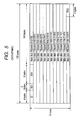
- the encoder 64 performs an 8-16 modulation with respect to each of the recording frames, and further, adds synchronous codes (SY0 to SY7) to the 8-16 modulated recording frame so as to form such a physical sector shown in Fig. 8.
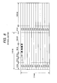
- Fig. 9 schematically shows an array example of pixels which constitute one sheet of image to be drawn in the image drawing layer 22 of the optical disk 10.
- Reference numeral "10c" indicates a center hole of the optical disk 10.
- the host apparatus 36 forms image data (monochromatic 2 gradation data) of the respective pixels of 0, 1, 2, 3, --- by this pixel array in advance prior to a commencement of the simultaneous recording/drawing operation (otherwise, in parallel with simultaneous recording/drawing operation), and then, sequentially transfers the formed image data in combination with the recording data to the optical disk drive 34 in accordance with the progress of the simultaneous recording/drawing operation.
- the encoder 64 of the optical disk drive 34 embeds the image data of the respective pixels 0, 1, 2, 3, ---, into the RSV areas of the relevant physical sector of the DVD format in such a manner that the respective pixels 0, 1, 2, 3, ---, are drawn at predetermined positions shown in Fig. 9 during the simultaneous recording/drawing operation.
- such an image data for 48 pixels is embedded within 1 physical sector (refer to Fig. 8), which are drawn in this 1 physical sector.
- both a data recording signal "NRZI” (refer to Fig. 1(a)) and a clock signal “NRZICLK” (refer to Fig. 1(b)) are outputted from the encoder 64.
- the data recording signal NRZI is finally formed by NRZI-modulating the DVD format data into which the image data is embedded, while the "NRZI"-modulation implies a "Non-Return to Zero Inverted” modulation.
- the above-described clock signal NRZICLK corresponds to such a clock signal having a time period of 1 T, which is formed based upon a wobble signal detected from the returned light of the DVD-purpose laser beam 30.
- the encoder 64 executes an encoding process operation based upon the clock signal NRZICLK. It should also be understood that the spindle control operation (CLV control operation) by the spindle servo 42 of Fig. 3 during the simultaneous recording/drawing operation is carried out in a PLL control mode in such a manner that the wobble signal detected from the returned light of the DVD-purpose laser beam 30 is synchronized with a predetermined crystal oscillated clock. As a consequence, when the simultaneous recording/drawing operation is performed, the encoding operation by the encoder 64 is synchronized with the rotating operation of the spindle motor 38.
- CLV control operation CLV control operation
- the strategy circuit 68 performs a time axis correction of the data recording signal NRZI in order to reduce jitter components, and thus, forms a data recording signal NRZI' whose time axis is corrected.
- the waveform of the signal NRZI is identical to the waveform of the signal NRZI' for the sake of convenience, the waveform of the signal NRZI' is actually corrected in the time axis with respect to the waveform of the signal NRZI.
- the DVD-purpose laser beam 30 is modulated by this data recording signal NRZI' whose time axis is corrected, so that a data recording operation is carried out.
- an "H" level of this data recording signal NRZI' constitutes such an instruction that the DVD-purpose laser beam 30 is driven in the recording power
- an "L” level thereof constitutes such an instruction that the DVD-purpose laser beam 30 is driven in the bottom power.
- the "H” level of the image drawing signal DOTX instructs laser power for changing the visible light characteristic of the image drawing layer 22, whereas the "L” level of the image drawing signal DOTX instructs laser power which does not change the visible light characteristic of the image drawing layer 22.
- a waveform pattern of a synchronous code SY0 (namely, synchronous code of head of physical sector, refer to Fig. 8) which is contained in the data recording signal NRZI becomes any one of Fig. 10A to Fig. 10D. At timing when these patterns appear is only when the synchronous code SY0 appears.
- Fig. 11 shows a temporal relationship between the data recording signal NRZI and the image drawing signal DOTX.
- the data converter 70 sequentially outputs the image drawing signal DOTX for 48 pixels for every time (806T) of 1/48 physical sectors after a predetermined process time " ⁇ Td" required in this data converter 70 is delayed.
- an image drawing signal DOTX for 1 pixel keeps either an "H” level (instruct laser power capable of changing visible light characteristic of image drawing layer 22) or an "L” level (instruct laser power which doe not change visible light characteristic of image drawing layer 22) for the allocated time (806T) of the 1/48 physical sectors.
- both the image drawing signal DOTX and an inverted signal as to the data recording signal NRZI' whose time axis is corrected are inputted to an AND circuit 72.
- the data recording signal NRZI' whose time axis is corrected is in an "H" level (laser power for forming pit is designated) as to a section of the "H" level (instruct laser power for changing visible light characteristic of image drawing layer 22) of the image drawing signal DOTX, such an image drawing signal DOTX' (see Fig.
- the level of the image drawing signal DOTX is temporarily lowered to the "L" level (instruct laser power which does not change visible light characteristic of image drawing layer 22) is outputted from the AND circuit 72.
- the CD-purpose laser beam 32 is modulated by this image drawing signal DOTX' so as to perform an image drawing operation.
- the "H" level of the image drawing signal DOTX' constitutes such an instruction that the CD-purpose laser beam 32 is driven in the image drawing power
- the "L" level of the image drawing signal DOTX' constitutes such an instruction that the CD-purpose laser beam 32 is driven in the bottom power.
- a unit length (namely, length of 1 pixel along disk circumferential direction) of an image drawing signal DOTX is equal to the 1/48 physical sectors (806T), whereas a pit length and a land length of a data recording signal NRZI are equal to 3T through 14T, so that plural pulses of the data recording signals NRZI may be entered per unit length of the image drawing signal DOTX. Similarly, plural pulses of data recording signals NRZI' whose time axis is corrected may be entered per unit length of the image drawing signal DOTX.
- an averaged duty of the data recording signal NRZI' is approximately 50%, and, within the section where the signal level of the image drawing signal DOTX is the "H" level, an averaged duty of the image drawing signal DOTX' which constitutes the inverted pattern of the data recording signal NRZI' is also equal to approximately 50%.
- the respective pixels can be drawn in the same density.
- Switches 74 and 76 are switched by a selection signal SEL supplied from the system control unit 44 in response to a recording mode.
- SEL selection signal
- this switch 74 When the switch 74 is being connected to the contact "1", this switch 74 outputs an "H” level signal in a continuous manner; when the switch 74 is being connected to the contact "2", this switch 74 outputs an "L” level signal in a continuous manner; and when the switch 74 is being connected to the contact "3", this switch 74 outputs the image drawing signal DOTX' modulated by the data recording signal NRZI'.
- this switch 76 When the switch 76 is being connected to the contacts "1" and “2”, this switch 76 outputs an "H” level signal in a continuous manner, whereas when the switch 76 is being connected to the contact "3", this switch 76 outputs the image drawing signal DOTX.
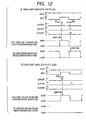
- Figs. 12A and 12b represent sampling operations of laser power in the ALPC circuit 58.
- Fig. 12A indicates a sampling operation when the signal level of the image drawing signal DOTX is in "H" level during the simultaneous recording/drawing operation; and
- Fig. 12B indicates a sampling operation when the signal level of the image drawing signal DOTX is in "L” level during the simultaneous recording/drawing operation.
- Sampling pulses ALPCSP1 and ALPCSP2 are outputted from the encoder 64.
- the sampling pulse ALPCSP1 is outputted after a predetermined time " ⁇ t1" ( ⁇ t1 is time during which laser power becomes stable) from a rising edge of the data recording signal NRZI.
- a sample and hold circuit 78 samples recording power of the DVD-purpose laser beam 30 by employing the sampling pulse ALPCSP1, while this recording power is detected by a front monitor 80 (which is commonly used by both laser beam 30 and 32) in the optical pickup 40 during simultaneous recording/drawing operation.
- a front monitor 80 which is commonly used by both laser beam 30 and 32
- both the image drawing signal DOTX and the sampling pulse ALPCSP2 are inputted to an AND circuit 82.
- the AND circuit 82 produces such a signal ALPCSP2' which causes the sampling pulse ALPCSP2 to pass therethrough when the image drawing signal DOTX is in an "H" level.
- the sample and hold circuit 84 samples image drawing power of the CD-purpose laser beam 32 detected by the front monitor 80 by using the sampling pulse ALPCSP2'. Since the power of the CD-purpose laser beam 32 is set to the bottom power of 0 mW (namely, CD-purpose laser beam 32 is not substantially turned ON) when the signal level of the image drawing signal DPTX is in an "L" level, this CD-purpose laser beam 32 cannot be sampled. As a consequence, while the sampling pulse ALPCSP2 is masked by the AND circuit 82, no sampling operation is carried out.
- a target value of recording power (for example, 30 mW) of the DVD-purpose laser beam 30 is outputted from a DAC (D/A converter) 86.
- a subtracting device 88 outputs a deviation value between the target value of the recording power and the sample and hold value. This deviation signal is smoothed by an LPF (low-pass filter) 90.
- An output signal of the LPF 90 is supplied via switches 92, 94, and 96 to an adding point 98 so as to be added therein to a bottom power instruction value outputted from a DAC (D/A converter) 100.
- This bottom power instruction value corresponds to, for instance, such a power instruction value of substantially 0 mW when the DVD-purpose laser diode 31 is driven by a threshold current.
- the added output signal is amplified by a laser driver 56a so as to drive the DVD-purpose laser diode 31 by the amplified output signal.
- the recording power of the DVD-purpose laser beam 30 is controlled in a servo loop in such a manner that this recording power is made coincident with the target value of the recording power set by the DAC 86, so that pits are formed in the data recording layer 16 by employing this recording power.
- a target value of image drawing power (for example, 40 mW) of the CD-purpose laser beam 32 is outputted from a DAC (D/A converter) 102.
- a subtracting device 104 outputs a deviation value between the target value of the image drawing power and the sample and hold value. This deviation signal is smoothed by an LPF (low-pass filter) 106.
- An output signal of the LPF 106 is supplied via the switches 92, 94, and 96 to an adding point 108 so as to be added therein to a bottom power instruction value outputted from a DAC (D/A converter) 111.
- This bottom power instruction value corresponds to, for instance, such a power instruction value of substantially 0 mW when the CD-purpose laser diode 33 is driven by a threshold current.
- the added output signal is amplified by a laser driver 56b so as to drive the CD-purpose laser diode 33 by the amplified output signal.
- the recording power of the CD-purpose laser beam 32 is controlled in a servo loop in such a manner that this image drawing power is made coincident with the target value of the image drawing power set by the DAC 102, so that the visible light characteristic of the image drawing layer 22 is changed by this image drawing power so as to perform an image drawing operation.
- the switch 92 is switched by the data recording signal NRZI'.
- the switch 92 when the signal level of the data recording signal NRZI' is in "H" level (pit forming instruction), the switch 92 selectively outputs a recording power drive signal of the DVD-purpose laser beam 30 outputted from the LPF 90.
- the switch 92 when the signal level of the data recording signal NRZI' is in "L" level (land forming instruction), the switch 92 selectively outputs an image forming power drive signal of the CD-purpose laser beam 32 outputted from the LPF 106.
- the switch 94 is switched by the image drawing signal DOTX' and the data recording signal NRZI' outputted from the OR circuit 113. That is to say, when any one of the image drawing signal DOTX' and the data recording signal NRZI' is in "H" level (pit forming instruction, or image drawing instruction), the switch 94 selectively outputs the output signal of the switch 92. Also, when both the image drawing signal DOTX' and the data recording signal NRZI' are in "L" levels (land forming instruction and no image drawing instruction), the switch 94 selectively outputs the "L” level signal.
- the switch 96 is switched by the image drawing signal DOTX'.
- this switch 96 supplies the output signal from the switch 94 as a drive signal of the CD-purpose laser beam 32. Also, when the signal level of the image forming signal DOTX' is in "L" level (no image drawing instruction), this switch 96 supplies the output signal from the switch 94 as a drive signal of the DVD-purpose laser beam 30.
- both the laser beam 30 and 32 are controlled as follows when the simultaneous recording/drawing operation is carried out:
- both the focusing control operation and the tracking control operation employ the averaged value servo (for example, average in several msec to several tens msec).
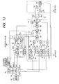
- Fig. 13 shows a detailed arrangement of an optical disk recording apparatus having the above arrangement. It should be noted that the same reference numerals shown in Fig. 4 will be employed as those for denoting similar structural elements of Fig. 13.
- a sample and hold circuit 115 samples bottom power of DVD-purpose laser beam 30 detected by the front monitor 80 based upon a sampling pulse ALPCSP2 when a simultaneous recording/image drawing operation is carried out.
- a target value of bottom power (for instance, 3 mW) of the DVD-purpose laser beam 30 is outputted from the DAC 117.
- a subtracting device 119 outputs a deviation value between the target value of the bottom power and the sample hold value. This deviation signal is smoothed by the LPF 121.
- the output signal of the LPF 121 is supplied to the adding point 98.
- Figs. 14A and 14B represents sampling operations of laser power in the ALPC circuit 58 of Fig. 13.
- Fig. 14A indicates a sampling operation when the signal level of the image drawing signal DOTX is an "H" level during the simultaneous recording/drawing operation; and
- Fig. 14B indicates a sampling operation when the signal level of the image drawing signal DOTX is an "L” level during the simultaneous recording/drawing operation.
- Sampling pulses ALPCSP1 and ALPCSP2 are outputted at the same timing as that of Figs. 12A and 12B. That is to say, the sampling pulse ALPCSP1 is outputted after a predetermined time " ⁇ t1" from a rising edge of the data recording signal NRZI.
- the bottom power of the DVD-purpose laser beam 30 is sampled based upon the sampling pulse ALPCSP2 even when the signal level of the image drawing signal DOTX is either an "H" level or an "L” level.
- the bottom power of the DVD-purpose laser beam 30 is controlled by the servo loop in such a manner that this bottom power is made coincident with the bottom power target value set by the DAC 117.
- the bottom power value of the DVD-purpose laser beam 30 is controlled to become higher than 0 mW and is brought into the turn-ON state, so that both a focusing error and a tracking error can be detected even at the timing of the bottom power.
- a sampling servo may also be employed in addition to the average value servo.
- step S1 When the optical disk 10 is loaded on the optical disk 10 and the simultaneous recording/drawing operation is instructed, the optical disk 10 is rotated (step S1).
- the DVD-purpose laser beam 30 is turned on in the reproducing power (at this time, switches 94 and 96 of Fig. 4 and Fig. 13 are temporarily connected to contacts "L" sides respectively, reproducing power instruction value is outputted from DAC 100 in Fig. 4, and reproducing power instruction value is outputted from DAC 117 in Fig. 13) (step S2).
- the focus servo 46 is turned on so as to focus the DVD-purpose laser beam 30 onto the data recording layer 16 (step S3).
- step S6 When such an address is detected at which the data recording operation is commenced (step S6), the reproducing power of the DVD-purpose laser beam 30 is switched to the recording power and the bottom power in response to the data recording signal NRZI' (see Fig. 1) (step S7). At the same time, the power of the CD-purpose laser beam 32 is switched to the image drawing power and the bottom power in response to the image drawing signal DOTX' (see Fig. 1) so as to start an image drawing operation (step S8).
- step S9 If the simultaneous recording/drawing operation is progressed and then the data recording operation is accomplished (step S9), then the DVD-purpose laser beam 30 is continuously turned on in the reproducing power (reproducing power instruction value is outputted from DAC 100) (step S10), and while both a focusing control operation and a tracking control operation are carried out by employing the DVD-purpose laser beam 30, the image drawing operation is continued by employing the CD-purpose laser beam 32. Then, when the CD-purpose laser beam 32 is reached to an image-drawing end position (step S11), the CD-purpose laser beam 32 is turned off so as to complete the image drawing operation (step S12). Thereafter, a read-in area of the data recording layer 16 is recorded by the DVD-purpose laser beam 30, if necessary, and then, all of the control operations are completed.
- the size of 1 pixel along the disk radial direction is set to the track pitch size (namely, 0.74 ⁇ m) based upon the wobble groove 14.
- this size of 1 pixel may be set to such a size defined by a plurality of track pitches.
- Fig. 16 shows one example in which the size of 1 pixel along the disk radial direction is set by the above-described alternative track pitch size. A meshed portion represents 1 pixel. In this alternative example, 4 pieces of track pitches (namely, 2.96 ⁇ m) are defined as the size of 1 pixel along the disk radial direction. Similar to Fig.
- the image data is contained in the empty area of the DVD format.
- the recording data and the image data may be separately encoded, so that a simultaneous recording/drawing operation may be carried out.
- the spindle motor 38 is controlled in the CLV control mode so as to perform the simultaneous recording/drawing operation.
- the spindle motor 38 may be controlled in the CAV (Constant Angular Velocity) control mode so as to perform the simultaneous recording/drawing operation.
- the CAV control mode is employed, the spindle motor 38 is controlled in the PLL control manner in such a manner that FG pulses outputted from the spindle motor 38 of Fig. 3 are detected at a predetermined frequency.
- the dimension of 1 pixel along the disk circumferential direction is defined as the constant length irrespective of the disk radial position.
- the dimension of 1 pixel along the disk circumferential direction may be defined as a constant rotation angle irrespective of the disk radial position.
- the simultaneous recording/drawing operation is carried out by employing the image drawable write-once type DVD.
- the present invention may be applied to simultaneous recording/drawing operations as to image drawable rewritable type DVDs (DVD-RW, DVD+RW, DVD-RAM etc.), an image drawable write-once type CD (CD-R), an image drawable rewritable type CD (CD-RW), image drawable write-once type Blue-ray disks (BD-R etc.), image drawable rewritable type Blue-ray disks (BD-RW etc.), and other sorts of image drawable optical disks.
Landscapes
- Physics & Mathematics (AREA)
- Optics & Photonics (AREA)
- Optical Recording Or Reproduction (AREA)
- Optical Head (AREA)
Applications Claiming Priority (1)
| Application Number | Priority Date | Filing Date | Title |
|---|---|---|---|
| JP2006258192A JP2008077797A (ja) | 2006-09-25 | 2006-09-25 | 光ディスク記録・描画方法 |
Publications (2)
| Publication Number | Publication Date |
|---|---|
| EP1903562A2 true EP1903562A2 (de) | 2008-03-26 |
| EP1903562A3 EP1903562A3 (de) | 2009-01-14 |
Family
ID=38788355
Family Applications (1)
| Application Number | Title | Priority Date | Filing Date |
|---|---|---|---|
| EP07018818A Withdrawn EP1903562A3 (de) | 2006-09-25 | 2007-09-25 | Verfahren zum Aufzeichnen/Zeichnen auf einer optischen Platte |
Country Status (4)
| Country | Link |
|---|---|
| US (1) | US20080074970A1 (de) |
| EP (1) | EP1903562A3 (de) |
| JP (1) | JP2008077797A (de) |
| CN (1) | CN101174427B (de) |
Families Citing this family (2)
| Publication number | Priority date | Publication date | Assignee | Title |
|---|---|---|---|---|
| DE102008018602B4 (de) * | 2008-04-11 | 2010-11-25 | Atmel Automotive Gmbh | Lasertreiberschaltung und Verwendung |
| JP5338855B2 (ja) * | 2011-06-07 | 2013-11-13 | 船井電機株式会社 | 光ディスク装置 |
Citations (2)
| Publication number | Priority date | Publication date | Assignee | Title |
|---|---|---|---|---|
| EP1422697A2 (de) | 2002-11-15 | 2004-05-26 | Yamaha Corporation | Verfahren, Programm und System zur Erzeugung eines sichtbaren Bildes auf einer optischen Platte |
| US20060193226A1 (en) | 2005-02-28 | 2006-08-31 | Sanyo Electric Co., Ltd. | Optical disk recording and playback device |
Family Cites Families (5)
| Publication number | Priority date | Publication date | Assignee | Title |
|---|---|---|---|---|
| JP4278820B2 (ja) * | 2000-03-31 | 2009-06-17 | パイオニア株式会社 | 光ディスク |
| JP4066927B2 (ja) * | 2003-09-30 | 2008-03-26 | ヤマハ株式会社 | 可視画像形成方法、プログラムおよび可視画像形成システム |
| JP3952504B2 (ja) * | 2004-03-11 | 2007-08-01 | 船井電機株式会社 | 録画再生装置及びその録画再生方法 |
| JP4436768B2 (ja) * | 2005-01-12 | 2010-03-24 | 三洋電機株式会社 | レーベル情報記録装置 |
| JP2006236529A (ja) * | 2005-02-28 | 2006-09-07 | Sanyo Electric Co Ltd | 光ディスク記録再生装置 |
-
2006
- 2006-09-25 JP JP2006258192A patent/JP2008077797A/ja active Pending
-
2007
- 2007-09-24 US US11/860,005 patent/US20080074970A1/en not_active Abandoned
- 2007-09-25 CN CN200710151660XA patent/CN101174427B/zh not_active Expired - Fee Related
- 2007-09-25 EP EP07018818A patent/EP1903562A3/de not_active Withdrawn
Patent Citations (2)
| Publication number | Priority date | Publication date | Assignee | Title |
|---|---|---|---|---|
| EP1422697A2 (de) | 2002-11-15 | 2004-05-26 | Yamaha Corporation | Verfahren, Programm und System zur Erzeugung eines sichtbaren Bildes auf einer optischen Platte |
| US20060193226A1 (en) | 2005-02-28 | 2006-08-31 | Sanyo Electric Co., Ltd. | Optical disk recording and playback device |
Also Published As
| Publication number | Publication date |
|---|---|
| EP1903562A3 (de) | 2009-01-14 |
| CN101174427B (zh) | 2011-11-16 |
| US20080074970A1 (en) | 2008-03-27 |
| JP2008077797A (ja) | 2008-04-03 |
| CN101174427A (zh) | 2008-05-07 |
Similar Documents
| Publication | Publication Date | Title |
|---|---|---|
| US6714509B2 (en) | Disk recording medium and disk drive apparatus | |
| EP1308942B1 (de) | Optische Platte, entsprechendes Gerät und verfahren | |
| US7817527B2 (en) | Optical disk drive and method for recording data | |
| US8045438B2 (en) | High frequency modulation of a light beam in optical recording | |
| EP1150291B1 (de) | Optisches Plattenlaufwerk, und Verfahren zur Aufzeichnung/Wiedergabe | |
| US8264926B2 (en) | Information recording medium with power calibration area | |
| US20050169147A1 (en) | Recording-medium evaluation method, recording/reproduction apparatus and recording medium | |
| JP4012925B2 (ja) | 光記録媒体、および、データ記録装置 | |
| EP1903562A2 (de) | Verfahren zum Aufzeichnen/Zeichnen auf einer optischen Platte | |
| CN1853221B (zh) | 记录光学记录载体的方法 | |
| EP1873763A1 (de) | Verfahren zum Zeichnen eines Bildes auf einer optischen Platte, optische Plattenvorrichtung und optisches Plattenaufzeichnungsmedium | |
| JP3888256B2 (ja) | コード化方法、光ディスクおよび光ディスク装置 | |
| US20050276212A1 (en) | Information record medium, and information record apparatus and method | |
| TWI264704B (en) | Method for identifying type of two-layer disc and optic disc device | |
| US20080069158A1 (en) | Laser power control technique and apparatus for recording and reproducing data in and from optical disk under laser power control | |
| CN102290059A (zh) | 信息擦除装置和信息擦除方法 | |
| JP4244917B2 (ja) | 情報記録媒体の記録パワ調整方法の選択方法及び情報記録装置 | |
| CN101377932B (zh) | 光盘的焦点位置调整方法及利用该方法的光盘装置 | |
| JP4201740B2 (ja) | 光ディスク記録方法および光ディスク記録装置 | |
| JP2001184678A (ja) | 光ディスク装置とそのフォーカス制御方法 | |
| JP4246567B2 (ja) | 情報記録装置 | |
| EP2549478A2 (de) | Optisches Plattenaufzeichnungsgerät | |
| WO2006028114A1 (ja) | 情報記録媒体、情報記録装置及び方法、並びにコンピュータプログラム | |
| JP4589205B2 (ja) | 情報記録媒体、情報記録装置及び方法、並びに、コンピュータプログラム | |
| US20080130438A1 (en) | Optical disk apparatus and control method therefor |
Legal Events
| Date | Code | Title | Description |
|---|---|---|---|
| PUAI | Public reference made under article 153(3) epc to a published international application that has entered the european phase |
Free format text: ORIGINAL CODE: 0009012 |
|
| AK | Designated contracting states |
Kind code of ref document: A2 Designated state(s): AT BE BG CH CY CZ DE DK EE ES FI FR GB GR HU IE IS IT LI LT LU LV MC MT NL PL PT RO SE SI SK TR |
|
| AX | Request for extension of the european patent |
Extension state: AL BA HR MK YU |
|
| PUAL | Search report despatched |
Free format text: ORIGINAL CODE: 0009013 |
|
| AK | Designated contracting states |
Kind code of ref document: A3 Designated state(s): AT BE BG CH CY CZ DE DK EE ES FI FR GB GR HU IE IS IT LI LT LU LV MC MT NL PL PT RO SE SI SK TR |
|
| AX | Request for extension of the european patent |
Extension state: AL BA HR MK RS |
|
| 17P | Request for examination filed |
Effective date: 20090713 |
|
| 17Q | First examination report despatched |
Effective date: 20090813 |
|
| AKX | Designation fees paid |
Designated state(s): DE FR GB |
|
| STAA | Information on the status of an ep patent application or granted ep patent |
Free format text: STATUS: THE APPLICATION IS DEEMED TO BE WITHDRAWN |
|
| 18D | Application deemed to be withdrawn |
Effective date: 20131125 |