EP1903681A1 - Procédé pour synchronisation de l'horloge d'un appareil électrique ave une horloge de référence et appareil électrique - Google Patents
Procédé pour synchronisation de l'horloge d'un appareil électrique ave une horloge de référence et appareil électrique Download PDFInfo
- Publication number
- EP1903681A1 EP1903681A1 EP06019806A EP06019806A EP1903681A1 EP 1903681 A1 EP1903681 A1 EP 1903681A1 EP 06019806 A EP06019806 A EP 06019806A EP 06019806 A EP06019806 A EP 06019806A EP 1903681 A1 EP1903681 A1 EP 1903681A1
- Authority
- EP
- European Patent Office
- Prior art keywords
- clock frequency
- clock
- time
- correction value
- difference
- Prior art date
- Legal status (The legal status is an assumption and is not a legal conclusion. Google has not performed a legal analysis and makes no representation as to the accuracy of the status listed.)
- Granted
Links
Images


Classifications
-
- H—ELECTRICITY
- H03—ELECTRONIC CIRCUITRY
- H03K—PULSE TECHNIQUE
- H03K5/00—Manipulating of pulses not covered by one of the other main groups of this subclass
- H03K5/13—Arrangements having a single output and transforming input signals into pulses delivered at desired time intervals
- H03K5/135—Arrangements having a single output and transforming input signals into pulses delivered at desired time intervals by the use of time reference signals, e.g. clock signals
-
- H—ELECTRICITY
- H03—ELECTRONIC CIRCUITRY
- H03L—AUTOMATIC CONTROL, STARTING, SYNCHRONISATION OR STABILISATION OF GENERATORS OF ELECTRONIC OSCILLATIONS OR PULSES
- H03L7/00—Automatic control of frequency or phase; Synchronisation
- H03L7/06—Automatic control of frequency or phase; Synchronisation using a reference signal applied to a frequency- or phase-locked loop
- H03L7/07—Automatic control of frequency or phase; Synchronisation using a reference signal applied to a frequency- or phase-locked loop using several loops, e.g. for redundant clock signal generation
-
- H—ELECTRICITY
- H03—ELECTRONIC CIRCUITRY
- H03L—AUTOMATIC CONTROL, STARTING, SYNCHRONISATION OR STABILISATION OF GENERATORS OF ELECTRONIC OSCILLATIONS OR PULSES
- H03L7/00—Automatic control of frequency or phase; Synchronisation
- H03L7/06—Automatic control of frequency or phase; Synchronisation using a reference signal applied to a frequency- or phase-locked loop
- H03L7/08—Details of the phase-locked loop
- H03L7/085—Details of the phase-locked loop concerning mainly the frequency- or phase-detection arrangement including the filtering or amplification of its output signal
- H03L7/091—Details of the phase-locked loop concerning mainly the frequency- or phase-detection arrangement including the filtering or amplification of its output signal the phase or frequency detector using a sampling device
Definitions
- the invention relates to a method for operating an electrical device, in particular an automation device, in which a correction of a clock frequency. It further relates to an electrical device, in particular an automation device, with means for carrying out the method.
- clock signals are generated, for example, by means of oscillators, wherein a regularity of the clock signals depends on a quality of the components used and on other factors, including aging processes of the components or environmental factors, e.g. Temperature or humidity, count, is affected.
- Very regular clock signals are based on atomic vibrations, which ensures high precision in atomic clocks.
- An object of the invention is to provide a method in which the abovementioned disadvantages are avoided or at least reduced in terms of their effects.
- This object is achieved by a method for operating an electrical device, in particular an automation device, in which a correction of a first clock frequency based on a second clock frequency and a reference clock frequency.
- a clock difference between the second clock frequency and the reference clock frequency is determined at least one predetermined or predefinable first time. From this clock difference, a correction value is derived, with which the first clock frequency is applied.
- a correction value is derived, with which the first clock frequency is applied.
- this object is achieved by a computer program with program code instructions for implementing the method when the computer program is executed on a computer, and by a computer program product, in particular storage medium, with the computer-executable computer program.
- an electrical device in particular an automation device, having means for carrying out the method, in particular a processing unit and a memory assigned to the processing unit.
- the computer program executable by the processing unit is stored in the memory.
- a regular and with the reference clock frequency substantially synchronous first clock frequency is generated at a lower frequency of synchronization, by means of which, for example, a drift is compensated.
- This lower frequency results in a minimization of the additional communication required for synchronization in the automation system. If the synchronization takes place permanently and automatically, an automatic calibration results without any external impact, e.g. an activity of the user, would be required, resulting in an increase in ease of use of the automation system.
- the second clock frequency is synchronized with the reference clock frequency at the or each predetermined or predefinable first time.
- the clock difference between the second clock frequency and the reference clock frequency is determined in connection with the synchronization of the second clock frequency with the reference clock frequency.
- a difference can be indicated, for example, as a difference of the second clock frequency and the reference clock frequency at any desired time, that is to say a relative difference, or as a totality for a period after the synchronization of determined differences, ie an absolute difference.
- a synchronization of the second clock frequency with the reference clock frequency resets the absolute difference of the clock frequencies, thus facilitating the determination of the correction value with which the first clock frequency is applied and reduces a possible error in the determination of the correction value which results from very large values of the difference would. If the clock difference in connection with the synchronization, ie, timely to a synchronization time is determined, then the clock difference between the second clock frequency and reference clock frequency has a maximum possible value for this method, thereby reducing a potential error in the determination of the clock difference and subsequently the correction value becomes.
- a synchronization of the first and the second clock frequency with the reference clock frequency takes place at least one predetermined or predefinable second time. This results in a simplification of the application of the first clock frequency with the mathematically or logically derived correction value from the clock difference between the second clock frequency and the reference clock frequency as well as a lesser potential error since there is no additive or multiplicative increase in the error.
- At least one correction value is determined for the first and at least one further time, at least one mean correction value is formed from the determined correction values and the first clock frequency is applied to the mean correction value, the average correction value is improved with each correction value used for its determination.
- an improvement in the correction value is achieved, and as the number of averaged correction values increases, an improvement in the synchronism of the first clock frequency and reference clock frequency and thus an improvement in quality is achieved.
- a first point in time and at least two further points in time are arranged equidistant from each other on a time axis, wherein in each case two successive points in time include a time interval.
- the correction value is determined in each case for such a time interval or at least a part thereof.
- the clock difference can be averaged or integrated over the entire time interval or at least part of the time interval.
- clock differences and / or correction values are averaged or integrated over a plurality of time intervals or parts thereof.
- either the clock difference or the correction value derived therefrom is related to a number of clocks of the reference clock frequency, via which either the clock difference or the correction value has been integrated or averaged. If the clock difference or the correction value has been determined or determined at a first time and this time is assigned to a preceding time interval, then the clock difference or the correction value is related to the number of reference clock frequency clocks of the time interval. This results in a correction value per clock for applying the first clock frequency.
- the first and the second clock frequency are selected so that a difference of these clock frequencies remains substantially the same.
- a deviation between the first clock frequency and the second clock frequency remains constant, ie a factor - a deviation factor - by which both clock frequencies differ is constant.
- the first clock frequency and the second clock frequency are substantially the same, which is achieved, for example, by using a clock frequency generator for generating the first and the second clock frequency or a use of substantially the same clock frequency, where "substantially equal” means here Clock frequency, which generate a substantially same clock frequency and the clock frequencies behave substantially the same, for example, with respect to drift.
- FIG. 1 shows a schematically simplified representation of an automation system 10 with a first electrical device, in particular a first automation device 12, for carrying out a method for correcting a clock frequency and a second automation device 14 with a reference frequency generator 16.
- the reference frequency generator 16 away from the automation system 10th be arranged.
- a first clock frequency generator 18 and a second clock frequency generator 20 are associated with the first automation device 12, the reference clock frequency generator 16 generating a reference clock frequency 22, the first clock frequency generator 18 generating a first clock frequency 24 and the second clock frequency generator 20 generating a second clock frequency 26.
- the second clock frequency generator 20 may be associated with the second automation device 14 or another automation device.
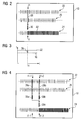
- FIG. 2 shows a schematically simplified representation of the method, wherein during operation of the automation system 10 according to FIG. 1 a correction of the first clock frequency 24 takes place on the basis of the second clock frequency 26 and the reference clock frequency 22.
- a clock difference 28 between the second clock frequency 26 and the reference clock frequency 22 is determined and derived from the clock difference 28, a correction value 30, with which the first clock frequency 24 is applied, for example by the correction value 30 is added to the first clock frequency 24.
- each clock 32 of the first clock frequency 24 is supplied with the correction value 30.
- FIG 3 shows a schematically simplified representation of the frequency f of the second clock frequency 26 and the reference clock frequency 22 over the time t, wherein a clock difference 28 between the second clock frequency 26 and reference clock frequency 22 at the first time t1 is determined.
- the second clock frequency 26 is substantially constant. Alternatively, however, this may also be a change, e.g. by drift, subject.
- FIG. 4 shows a schematically simplified illustration of an alternative embodiment of the method illustrated in FIG. 2, wherein a clock difference 28a, 28b is determined for a first time t1-1 and another time t1-2 and a correction value 30a, 30b is derived therefrom. From these correction values 30a, 30b, a mean correction value 30c is formed and the first clock frequency 24 is applied to the mean correction value 30c.
- Three equidistant times t1-1, t1-2, t1-3 include two likewise equidistant and equally long time intervals ⁇ t1, ⁇ t2. For each time interval ⁇ t1, ⁇ t2, a clock difference 28a, 28b between the second clock frequency 26 and the reference clock frequency 22 is determined and a respective correction value 30a, 30b is derived, with which the first clock frequency 24 is applied.
- FIG. 6 shows a schematically simplified illustration of an electrical device, in particular an automation device 12, with a processing unit 34 and a memory 36 associated memory 34, in which a computer program for performing the method is stored and which is executable by the processing unit 34.
- the invention relates to a method for operating an electrical device, in particular an automation device 12, in which a correction of a first clock frequency 24 based on a second clock frequency 26 and a reference clock frequency 22 takes place. At least one predetermined or predefinable first time t1, a clock difference 28 between the second clock frequency 26 and the reference clock frequency 22 is determined and derived from the clock difference 28, a correction value 30, with which the first clock frequency 24 is applied.
Landscapes
- Physics & Mathematics (AREA)
- Nonlinear Science (AREA)
- Synchronisation In Digital Transmission Systems (AREA)
Priority Applications (2)
| Application Number | Priority Date | Filing Date | Title |
|---|---|---|---|
| EP20060019806 EP1903681B1 (fr) | 2006-09-21 | 2006-09-21 | Procédé pour synchronisation de l'horloge d'un appareil électrique ave une horloge de référence et appareil électrique |
| DE200650004321 DE502006004321D1 (de) | 2006-09-21 | 2006-09-21 | Verfahren zur Taktsynchronisation eines elektrischen Geräts auf einen Referenztakt und elektrisches Gerät |
Applications Claiming Priority (1)
| Application Number | Priority Date | Filing Date | Title |
|---|---|---|---|
| EP20060019806 EP1903681B1 (fr) | 2006-09-21 | 2006-09-21 | Procédé pour synchronisation de l'horloge d'un appareil électrique ave une horloge de référence et appareil électrique |
Publications (2)
| Publication Number | Publication Date |
|---|---|
| EP1903681A1 true EP1903681A1 (fr) | 2008-03-26 |
| EP1903681B1 EP1903681B1 (fr) | 2009-07-22 |
Family
ID=37714629
Family Applications (1)
| Application Number | Title | Priority Date | Filing Date |
|---|---|---|---|
| EP20060019806 Active EP1903681B1 (fr) | 2006-09-21 | 2006-09-21 | Procédé pour synchronisation de l'horloge d'un appareil électrique ave une horloge de référence et appareil électrique |
Country Status (2)
| Country | Link |
|---|---|
| EP (1) | EP1903681B1 (fr) |
| DE (1) | DE502006004321D1 (fr) |
Cited By (1)
| Publication number | Priority date | Publication date | Assignee | Title |
|---|---|---|---|---|
| DE102022108316A1 (de) | 2022-04-06 | 2023-10-12 | Endress+Hauser SE+Co. KG | Verfahren zur Überprüfung mindestens eines ersten Taktgebers eines ersten Feldgeräts in einem Prozessmesssystem |
Citations (6)
| Publication number | Priority date | Publication date | Assignee | Title |
|---|---|---|---|---|
| US6052034A (en) * | 1998-06-24 | 2000-04-18 | Industrial Technology Research Institute | Method and apparatus for all digital holdover circuit |
| US6166606A (en) * | 1999-02-10 | 2000-12-26 | Zilog, Inc. | Phase and frequency locked clock generator |
| DE10022486C1 (de) | 2000-05-09 | 2002-01-17 | Infineon Technologies Ag | Digitaler Phasenregelkreis |
| US20030197537A1 (en) * | 2002-04-19 | 2003-10-23 | Martin Saint-Laurent | Clock distribution network using feedback for skew compensation and jitter filtering |
| WO2004034631A1 (fr) * | 2002-10-10 | 2004-04-22 | Infineon Technologies Ag | Dispositif d'extraction de signal d'horloge et procede d'extraction de signal d'horloge a partir d'un signal de donnees |
| EP1557951A1 (fr) * | 2004-01-21 | 2005-07-27 | Telefonaktiebolaget LM Ericsson (publ) | Générateur de fréquence avec oscillateurs multiples commandé en tension |
-
2006
- 2006-09-21 DE DE200650004321 patent/DE502006004321D1/de active Active
- 2006-09-21 EP EP20060019806 patent/EP1903681B1/fr active Active
Patent Citations (6)
| Publication number | Priority date | Publication date | Assignee | Title |
|---|---|---|---|---|
| US6052034A (en) * | 1998-06-24 | 2000-04-18 | Industrial Technology Research Institute | Method and apparatus for all digital holdover circuit |
| US6166606A (en) * | 1999-02-10 | 2000-12-26 | Zilog, Inc. | Phase and frequency locked clock generator |
| DE10022486C1 (de) | 2000-05-09 | 2002-01-17 | Infineon Technologies Ag | Digitaler Phasenregelkreis |
| US20030197537A1 (en) * | 2002-04-19 | 2003-10-23 | Martin Saint-Laurent | Clock distribution network using feedback for skew compensation and jitter filtering |
| WO2004034631A1 (fr) * | 2002-10-10 | 2004-04-22 | Infineon Technologies Ag | Dispositif d'extraction de signal d'horloge et procede d'extraction de signal d'horloge a partir d'un signal de donnees |
| EP1557951A1 (fr) * | 2004-01-21 | 2005-07-27 | Telefonaktiebolaget LM Ericsson (publ) | Générateur de fréquence avec oscillateurs multiples commandé en tension |
Cited By (1)
| Publication number | Priority date | Publication date | Assignee | Title |
|---|---|---|---|---|
| DE102022108316A1 (de) | 2022-04-06 | 2023-10-12 | Endress+Hauser SE+Co. KG | Verfahren zur Überprüfung mindestens eines ersten Taktgebers eines ersten Feldgeräts in einem Prozessmesssystem |
Also Published As
| Publication number | Publication date |
|---|---|
| DE502006004321D1 (de) | 2009-09-03 |
| EP1903681B1 (fr) | 2009-07-22 |
Similar Documents
| Publication | Publication Date | Title |
|---|---|---|
| DE10291119B4 (de) | Verfahren und Vorrichtung zur Synchronisation der Zykluszeit von mehreren Bussen, wobei mindestens einer der Busse ein TTCAN Bus ist, sowie entsprechendes Bussystem | |
| WO2017001603A2 (fr) | Dispositif pour générer plusieurs signaux d'horloge ou haute fréquence | |
| EP1325578A2 (fr) | Procede de synchronisation commandee sur un systeme d'horloge non stable et unite de reception correspondante | |
| EP3438773A1 (fr) | Usinage de pièces à compensation d'erreur basées sur modèles | |
| DE19722114C2 (de) | Taktsignal-Bereitstellungsvorrichtung und -verfahren | |
| DE112006003101T5 (de) | Verfahren und Vorrichtung zum Einstellen von synchronen Taktsignalen | |
| EP1395885B1 (fr) | Procede d'exploitation d'un systeme de mesure de position | |
| EP2299614B1 (fr) | Dispositif et procédé de synchronisation temporelle dans un réseau de communication | |
| WO2002028003A2 (fr) | Procede pour synchroniser plusieurs systemes de bus et systeme de bus hierarchique correspondant | |
| EP1903681B1 (fr) | Procédé pour synchronisation de l'horloge d'un appareil électrique ave une horloge de référence et appareil électrique | |
| DE3855895T2 (de) | Taktsignal-Versorgungssystem | |
| DE19828967A1 (de) | Verfahren zur Messung und Kompensation eines ungenauen Taktsignals | |
| EP3783317B1 (fr) | Dispositif capteur à synchronisation d'un signal de capteur sur un signal d'interrogation | |
| DE102008019287A1 (de) | Verfahren zum automatischen Erzeugen eines Zeitschemas für kommunizierende verteilte Prozesse eines digitalen Netzwerks | |
| DE102005039450B4 (de) | Verfahren und Netzwerk zur synchronen Bearbeitung und Bereitstellung von Daten | |
| DE2835200B2 (de) | Verfahren und Schaltung zur Einstellung einer elektronischen digitalen Anzeige einer Sollzeitdauer | |
| DE102016205301B4 (de) | Verfahren und Vorrichtung zum Regeln einer elektrischen Maschine | |
| EP0715412A1 (fr) | Procédé et dispositif d'investigation des variations de phase du signal d'entrée de référence d'une boucle à verrouillage de phase | |
| EP2928110A1 (fr) | Procédé de synchronisation d'un système isochrone doté d'un système d'horloge maître | |
| EP4327178B1 (fr) | Dispositif et procédé de surveillance assistée par ordinateur de deux bases temporelles de deux dispositifs de communication | |
| DE2747438C3 (de) | Schaltungsanordnung zum phasenstarren Nachführen eines Ausgangssignals in Abhängigkeit eines Eingangssignals | |
| EP2476029B1 (fr) | Synchronisation temporelle dans des appareils d'automatisation | |
| EP2203998B1 (fr) | Procédé de détermination de la cadence physique d'un noeud réseau | |
| WO2002007313A1 (fr) | Procede et dispositif d'evaluation de la puissance d'un circuit d'attaque | |
| DE102024202220A1 (de) | Verfahren zum Kalibrieren von Stromsensoren, Regelvorrichtung für ein elektrisches Antriebssystem und elektrisches Antriebssystem |
Legal Events
| Date | Code | Title | Description |
|---|---|---|---|
| PUAI | Public reference made under article 153(3) epc to a published international application that has entered the european phase |
Free format text: ORIGINAL CODE: 0009012 |
|
| AK | Designated contracting states |
Kind code of ref document: A1 Designated state(s): AT BE BG CH CY CZ DE DK EE ES FI FR GB GR HU IE IS IT LI LT LU LV MC NL PL PT RO SE SI SK TR |
|
| AX | Request for extension of the european patent |
Extension state: AL BA HR MK YU |
|
| 17P | Request for examination filed |
Effective date: 20080411 |
|
| 17Q | First examination report despatched |
Effective date: 20080520 |
|
| AKX | Designation fees paid |
Designated state(s): DE FR GB IT |
|
| GRAP | Despatch of communication of intention to grant a patent |
Free format text: ORIGINAL CODE: EPIDOSNIGR1 |
|
| GRAS | Grant fee paid |
Free format text: ORIGINAL CODE: EPIDOSNIGR3 |
|
| GRAA | (expected) grant |
Free format text: ORIGINAL CODE: 0009210 |
|
| AK | Designated contracting states |
Kind code of ref document: B1 Designated state(s): DE FR GB IT |
|
| REG | Reference to a national code |
Ref country code: GB Ref legal event code: FG4D Free format text: NOT ENGLISH |
|
| REF | Corresponds to: |
Ref document number: 502006004321 Country of ref document: DE Date of ref document: 20090903 Kind code of ref document: P |
|
| PLBE | No opposition filed within time limit |
Free format text: ORIGINAL CODE: 0009261 |
|
| STAA | Information on the status of an ep patent application or granted ep patent |
Free format text: STATUS: NO OPPOSITION FILED WITHIN TIME LIMIT |
|
| 26N | No opposition filed |
Effective date: 20100423 |
|
| REG | Reference to a national code |
Ref country code: FR Ref legal event code: PLFP Year of fee payment: 11 |
|
| REG | Reference to a national code |
Ref country code: FR Ref legal event code: PLFP Year of fee payment: 12 |
|
| REG | Reference to a national code |
Ref country code: FR Ref legal event code: PLFP Year of fee payment: 13 |
|
| PGFP | Annual fee paid to national office [announced via postgrant information from national office to epo] |
Ref country code: GB Payment date: 20230904 Year of fee payment: 18 |
|
| PGFP | Annual fee paid to national office [announced via postgrant information from national office to epo] |
Ref country code: IT Payment date: 20231011 Year of fee payment: 20 |
|
| GBPC | Gb: european patent ceased through non-payment of renewal fee |
Effective date: 20240921 |
|
| PG25 | Lapsed in a contracting state [announced via postgrant information from national office to epo] |
Ref country code: GB Free format text: LAPSE BECAUSE OF NON-PAYMENT OF DUE FEES Effective date: 20240921 |
|
| PGFP | Annual fee paid to national office [announced via postgrant information from national office to epo] |
Ref country code: FR Payment date: 20250915 Year of fee payment: 20 |
|
| PGFP | Annual fee paid to national office [announced via postgrant information from national office to epo] |
Ref country code: DE Payment date: 20251120 Year of fee payment: 20 |