EP4327178B1 - Dispositif et procédé de surveillance assistée par ordinateur de deux bases temporelles de deux dispositifs de communication - Google Patents
Dispositif et procédé de surveillance assistée par ordinateur de deux bases temporelles de deux dispositifs de communication Download PDFInfo
- Publication number
- EP4327178B1 EP4327178B1 EP22734134.4A EP22734134A EP4327178B1 EP 4327178 B1 EP4327178 B1 EP 4327178B1 EP 22734134 A EP22734134 A EP 22734134A EP 4327178 B1 EP4327178 B1 EP 4327178B1
- Authority
- EP
- European Patent Office
- Prior art keywords
- time
- drift
- measuring step
- interval
- instant
- Prior art date
- Legal status (The legal status is an assumption and is not a legal conclusion. Google has not performed a legal analysis and makes no representation as to the accuracy of the status listed.)
- Active
Links
Images


Classifications
-
- G—PHYSICS
- G06—COMPUTING OR CALCULATING; COUNTING
- G06F—ELECTRIC DIGITAL DATA PROCESSING
- G06F1/00—Details not covered by groups G06F3/00 - G06F13/00 and G06F21/00
- G06F1/04—Generating or distributing clock signals or signals derived directly therefrom
- G06F1/14—Time supervision arrangements, e.g. real time clock
-
- H—ELECTRICITY
- H04—ELECTRIC COMMUNICATION TECHNIQUE
- H04W—WIRELESS COMMUNICATION NETWORKS
- H04W56/00—Synchronisation arrangements
- H04W56/001—Synchronization between nodes
-
- B—PERFORMING OPERATIONS; TRANSPORTING
- B61—RAILWAYS
- B61L—GUIDING RAILWAY TRAFFIC; ENSURING THE SAFETY OF RAILWAY TRAFFIC
- B61L27/00—Central railway traffic control systems; Trackside control; Communication systems specially adapted therefor
- B61L27/50—Trackside diagnosis or maintenance, e.g. software upgrades
- B61L27/53—Trackside diagnosis or maintenance, e.g. software upgrades for trackside elements or systems, e.g. trackside supervision of trackside control system conditions
-
- B—PERFORMING OPERATIONS; TRANSPORTING
- B61—RAILWAYS
- B61L—GUIDING RAILWAY TRAFFIC; ENSURING THE SAFETY OF RAILWAY TRAFFIC
- B61L27/00—Central railway traffic control systems; Trackside control; Communication systems specially adapted therefor
- B61L27/70—Details of trackside communication
-
- G—PHYSICS
- G06—COMPUTING OR CALCULATING; COUNTING
- G06F—ELECTRIC DIGITAL DATA PROCESSING
- G06F9/00—Arrangements for program control, e.g. control units
- G06F9/06—Arrangements for program control, e.g. control units using stored programs, i.e. using an internal store of processing equipment to receive or retain programs
- G06F9/30—Arrangements for executing machine instructions, e.g. instruction decode
- G06F9/30003—Arrangements for executing specific machine instructions
- G06F9/3004—Arrangements for executing specific machine instructions to perform operations on memory
- G06F9/30043—LOAD or STORE instructions; Clear instruction
-
- H—ELECTRICITY
- H04—ELECTRIC COMMUNICATION TECHNIQUE
- H04J—MULTIPLEX COMMUNICATION
- H04J3/00—Time-division multiplex systems
- H04J3/02—Details
- H04J3/06—Synchronising arrangements
- H04J3/0635—Clock or time synchronisation in a network
- H04J3/0638—Clock or time synchronisation among nodes; Internode synchronisation
- H04J3/0658—Clock or time synchronisation among packet nodes
-
- H—ELECTRICITY
- H04—ELECTRIC COMMUNICATION TECHNIQUE
- H04J—MULTIPLEX COMMUNICATION
- H04J3/00—Time-division multiplex systems
- H04J3/02—Details
- H04J3/06—Synchronising arrangements
- H04J3/0635—Clock or time synchronisation in a network
- H04J3/0638—Clock or time synchronisation among nodes; Internode synchronisation
- H04J3/0658—Clock or time synchronisation among packet nodes
- H04J3/0661—Clock or time synchronisation among packet nodes using timestamps
- H04J3/0667—Bidirectional timestamps, e.g. NTP or PTP for compensation of clock drift and for compensation of propagation delays
-
- H—ELECTRICITY
- H04—ELECTRIC COMMUNICATION TECHNIQUE
- H04L—TRANSMISSION OF DIGITAL INFORMATION, e.g. TELEGRAPHIC COMMUNICATION
- H04L43/00—Arrangements for monitoring or testing data switching networks
- H04L43/08—Monitoring or testing based on specific metrics, e.g. QoS, energy consumption or environmental parameters
- H04L43/0852—Delays
- H04L43/0858—One way delays
-
- H—ELECTRICITY
- H04—ELECTRIC COMMUNICATION TECHNIQUE
- H04L—TRANSMISSION OF DIGITAL INFORMATION, e.g. TELEGRAPHIC COMMUNICATION
- H04L43/00—Arrangements for monitoring or testing data switching networks
- H04L43/16—Threshold monitoring
-
- H—ELECTRICITY
- H04—ELECTRIC COMMUNICATION TECHNIQUE
- H04N—PICTORIAL COMMUNICATION, e.g. TELEVISION
- H04N21/00—Selective content distribution, e.g. interactive television or video on demand [VOD]
- H04N21/40—Client devices specifically adapted for the reception of or interaction with content, e.g. set-top-box [STB]; Operations thereof
- H04N21/43—Processing of content or additional data, e.g. demultiplexing additional data from a digital video stream; Elementary client operations, e.g. monitoring of home network or synchronising decoder's clock; Client middleware
- H04N21/434—Disassembling of a multiplex stream, e.g. demultiplexing audio and video streams, extraction of additional data from a video stream; Remultiplexing of multiplex streams; Extraction or processing of SI; Disassembling of packetised elementary stream
- H04N21/4341—Demultiplexing of audio and video streams
Definitions
- a method that uses the Christian algorithm to estimate a time offset between two time bases is described in the WO 2019/223951 A1 described.
- Using the Christian algorithm several time offset intervals are determined, whereby auxiliary windows for a possible time offset can be formed by extrapolating successive time offset intervals while taking into account an assumed drift of the time offset.
- a resulting time offset interval can be determined which has a smaller error compared to the time offset intervals of the previous measurements.
- the invention is based on the object of specifying a method for computer-aided monitoring of a first time base of a first communication device and a second time base of a second communication device, with which a time offset between the time bases or a drift of the time offset can be determined as accurately as possible in the shortest possible time in order to monitor the two communication devices using the result.
- the object of the invention is also to specify a computer program product and a provision device for this computer program product, with which the aforementioned method can be carried out.
- the first process involves implementing the Christian algorithm described at the beginning. After determining the four points in time mentioned, the time offset interval ⁇ (n) is determined according to the Christian algorithm. This interval specifies the interval for a possible time offset within which the time offset, i.e. the absolute time difference between the first time base and the second time base based on the measured points in time, can only lie.
- the Christian algorithm proceeds in such a way that the time offset ⁇ (n) is calculated from the first time, the second time, the third time and the fourth time.
- a maximum possible error for the time offset e(n) can be calculated from the first time, the second time, the third time and the fourth time and, taking the maximum possible error into account, an upper bound and a lower bound of the time offset interval can be calculated (more on this below).
- the first sequence contains at least three measuring steps. This can be justified by the fact that the first sequence must form the basis for carrying out the second sequence. In this, two measuring steps each must be considered several times, namely an earlier measuring step n and a later measuring step n+x.
- n indicates the number of the measuring step and is a natural number.
- a later measuring step is at a distance x from the earlier measuring step, which is also a natural number. For an adjacent later measuring step, x would therefore be 1. If a minimum of three measuring steps are carried out in the first sequence, a maximum of three comparisons can be carried out in the second sequence: namely the comparison of measuring steps 1 and 2, measuring steps 2 and 3 and measuring steps 1 and 3. If n > 3, the possible combinations increase.
- the resulting time offset interval of both measurements can be used to determine a maximum possible change in the time offset (also called drift) and a minimum possible change in the time offset, taking into account the measurement uncertainty determined by the time offset interval.
- a maximum possible drift results when the time offset in the earlier measurement step is assumed to be minimal and the time offset in the later measurement step is assumed to be maximum within the respective time offset interval. For this reason, the lower limit of the time offset interval for the earlier measurement step and the upper limit of the time offset interval for the later measurement step are taken into account.
- a minimum possible drift results when the time offset in the earlier measurement step is assumed to be maximum and the time offset in the later measurement step is assumed to be minimal. For this reason, in this case, the upper limit of the time offset interval of the earlier measurement step and the upper limit of the time offset interval of the later measurement step are taken into account.
- the aim of the method can be, for example, to monitor the synchronization of the two time bases. This involves determining a relative time offset between the first time base and the second time base. Monitoring can also be carried out by determining the drift. If monitoring determines that synchronization can no longer be carried out due to a growing time offset or progressive drift, appropriate countermeasures must be initiated (more on this below).
- the countermeasures can, for example, consist of an error message or also a correction, ie reduction of the time offset.
- the time offset in a measuring step n is calculated on the basis of the transmission time of the first message as the time difference between the first time and the second time and the transmission time of the second message as the time difference between the third time and the fourth time.
- the measured message runtime is not the actual message runtime. This can be explained by the fact that the measurement is subject to measurement errors.
- the largest measurement error is that the time difference between the first time and the fourth time does not take into account that there is a reaction time in the second communication device from receiving the first message to sending the second message.
- the latter measurement error is, however, easy to determine. It consists of the measured reaction time, which can be calculated as the time difference between the second time and the third time and therefore reduces the measured message runtime by the measured reaction time. Therefore, if the measured reaction time is subtracted from the measured message runtime, the result will be a better approximation of the actual message runtime.
- the result is a measure of the maximum possible error, if one takes into account that the signal propagation times can fluctuate due to irregularities in the transmission path. These fluctuations are large compared to the measurement accuracy in determining the relevant points in time to be measured. Therefore, a measurement error due to fluctuations in the transmission, which are determined taking into account the response time of the second communication device, can be estimated with sufficient accuracy.
- the time difference between the fourth point in time and the first point in time indicates the measured signal propagation time.
- the reaction time of the second communication device determined by the time difference between the third point in time and the second point in time, can be subtracted from this. Since there are two transmissions, the result (denominator) can be divided by two to get the maximum possible error per transmission.
- the above-mentioned calculation formulas advantageously provide an algorithm with which the intervals from an earlier measurement step and a later measurement step can be calculated in a computer-aided manner while maintaining short arithmetic symbols.
- An evaluation can be carried out after each time interval by carrying out the third process.
- determining the length of the time interval it can be taken into account that the following conditions are met for the second process to be carried out.
- the time interval must be long enough to allow the required number of measurement steps to be carried out. It must also be taken into account that the time interval must be long enough to allow any drift in the time offset to be detected by measurement.
- the time base of one communication device is defined as a reference by the first communication device and the second communication device and the time base of the other communication device is modified taking into account the resulting drift.
- the following known measures can be taken to align the first time base and the second time base.
- the time base that is not used as a reference can be slowed down or accelerated as required to reduce a time offset from the time base that is used as a reference.
- Another possibility is to correct the time measurement in steps (so-called stepping).
- a system within the meaning of the invention is a technical system in which data exchange between different communication devices of the system is required. This is particularly the case if the system has several computers that must be operated in such a way that synchronized data exchange via the first communication device and the second communication device is required.
- the interface for establishing the communication connection is provided by a cloud.
- cloud refers to an environment for “cloud computing”. This refers to an IT infrastructure that is made available via interfaces of a network such as the Internet. It usually includes storage space, computing power or software as a service, without these having to be installed on the local computer using the cloud.
- the services offered as part of cloud computing cover the entire spectrum of information technology and include infrastructure, platforms and software.
- railway systems such as signal boxes benefit particularly from the application of the method according to the invention, since reliable synchronization of communicating components of the railway system must be ensured.
- a provision device for storing and/or providing the computer program product.
- the provision device is, for example, a Storage unit that stores and/or provides the computer program product.
- the provision device is, for example, a network service, a computer system, a server system, in particular a distributed, for example cloud-based computer system and/or virtual computer system, which stores and/or provides the computer program product preferably in the form of a data stream.
- the provision takes place in the form of a program data block as a file, in particular as a download file, or as a data stream, in particular as a download data stream, of the computer program product.
- This provision can also take place, for example, as a partial download consisting of several parts.
- Such a computer program product is read into a system, for example, using the provision device, so that the method according to the invention is carried out on a computer.
- the exemplary embodiments explained below are preferred embodiments of the invention.
- the components of the embodiments described each represent individual features of the invention that are to be considered independently of one another, which also develop the invention independently of one another and are therefore to be considered as part of the invention individually or in a combination other than that shown.
- the components described can also be combined with the features of the invention described above.
- a subsequent query step t>ZI checks whether the elapsed time t is still less than a defined time interval ZI (which is set to one minute, for example) and has not yet been reached. If this is the case, one of the three alternative procedures mentioned above is repeated. However, if the time interval ZI has elapsed, the first procedure AL1 is completed, with the alternative procedure for determining a time offset interval COW being carried out at least three times.
- a defined time interval ZI which is set to one minute, for example
- a query step NXT CMB it is queried whether another combination of measurement steps should be examined.
- a change step CNG n,x another previous Measuring step n and/or another distance x between the earlier measuring step n and the later measuring step n+x is specified.
- the procedure as explained above for determining a further drift interval CDW can be carried out again.
- the third process AL3 can begin.
- This consists of a comparison step CMP CDW, in which the available drift intervals CDW determined in the second process AL2 are compared with one another.
- the smallest determined upper limit of the drift interval ⁇ o and the largest determined lower limit ⁇ u of the determined drift intervals CDW from the second process AL2 are selected, whereby these can belong to different drift intervals CDW.
- ST RCDW a resulting drift interval RCDW is determined from these two determined limits, i.e.
- a resulting drift value ⁇ r can be calculated from the resulting drift window RCDW in a calculation step CLC ⁇ r, in which the resulting drift value ⁇ r is calculated, for example, as the mean value of the upper bound of the drift ⁇ o and the lower bound of the drift ⁇ u (relative to the resulting drift window RCDW).
- a correction step CRC ZB it is possible to correct one of the two time bases ZB in a correction step CRC ZB, i.e. to resynchronize the first time base ZB1 and the second time base ZB2.
- One time base can be used as a reference and the other time base can be adjusted to the time base used as a reference (step by step or by accelerating or slowing down the time base to be corrected).
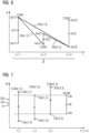
- the calculated time offset ⁇ is shown on the y-axis.
- an average value ⁇ (1) can be determined, which is not important for the further calculation presented here.
- This also applies analogously to the second time offset window COW2 and the third time offset window COW3. Additional time offset windows COW4 ... can be determined within the time interval ZI (not shown).
- the slope of a straight line ⁇ o(1, 2) through the two points mentioned is precisely the maximum possible drift when considering these two time offset windows, given the time interval between measurements 1 and 2.
- the time intervals between the individual measurements n can be determined, for example, by calculating the difference between the respective points in time t4 (cf. Figure 1 ) can be determined.
- drift intervals CDW were determined for each of the combinations of measurements considered, i.e. for measurements 1 and 2 the drift interval CDW(1, 2), for measurements 1 and 3 the drift interval CDW(1, 3) and for measurements 2 and 3 the drift interval CDW(2, 3). These each represent the interval within which a true drift ⁇ reliably lies. It should be noted that the actual drift ⁇ is still not known.
- the presence of several drift intervals CDW allows the resulting drift interval RCDW to be further limited.
- the smallest upper bound ⁇ o of the drift intervals CDW (in Figure 7 ⁇ o(1, 3)) and the largest lower bound ⁇ u of the drift intervals (in Figure 7 ⁇ u(2, 3)) are defined as the upper limit ⁇ o and the lower limit ⁇ u of the resulting drift interval RCDW.
- the resulting drift interval RCDW is the intersection of the evaluated individual drift intervals CDW. This limits this interval and a resulting drift ⁇ r can be calculated, for example, by forming the average of the upper limit ⁇ o and the lower limit ⁇ u of the resulting drift interval RCDW. However, this calculation is based on a statistical evaluation and can, as in Figure 7 shown, deviate from the actual drift ⁇ .
Landscapes
- Engineering & Computer Science (AREA)
- Signal Processing (AREA)
- Computer Networks & Wireless Communication (AREA)
- Theoretical Computer Science (AREA)
- Software Systems (AREA)
- Physics & Mathematics (AREA)
- General Engineering & Computer Science (AREA)
- General Physics & Mathematics (AREA)
- Mechanical Engineering (AREA)
- Environmental & Geological Engineering (AREA)
- Multimedia (AREA)
- Health & Medical Sciences (AREA)
- Biomedical Technology (AREA)
- General Health & Medical Sciences (AREA)
- Management, Administration, Business Operations System, And Electronic Commerce (AREA)
- Synchronisation In Digital Transmission Systems (AREA)
- Mobile Radio Communication Systems (AREA)
- Data Exchanges In Wide-Area Networks (AREA)
Claims (15)
- Procédé de contrôle assisté par ordinateur d'une première base (ZB1) de temps d'un premier dispositif de communication et d'une deuxième base (ZB2) de temps d'un deuxième dispositif de communication, dans lequel, dans un premier déroulement, on effectue au moins trois stades (n) de mesure, dans lequel, dans chaque stade de mesure respectivement• à un premier instant (T1), qui est rapporté à la première base (ZB1) de temps, on envoie un premier message (N1) du premier dispositif (K1) de communication au deuxième dispositif (K2) de communication,• à un deuxième instant (T2), qui est rapporté à la deuxième base (ZB2) de temps, on reçoit le premier message (N1) par le deuxième dispositif (K2) de communication,• à un troisième instant (T3), qui est rapporté à la deuxième base (ZB2) de temps, on envoie un deuxième message (N2) par le deuxième dispositif (K2) de communication au premier dispositif (K1) de communication, et• à un quatrième instant (T4), qui est rapporté à la première base (ZB1) de temps, on reçoit le deuxième message (N2) du premier dispositif (K1) de communication,• à partir du premier instant, du deuxième instant, du troisième instant et du quatrième instant, on détermine un intervalle (COW) de décalage de temps, dans lequel il peut y avoir un décalage de temps entre la première base de temps et la deuxième base de temps,dans lequel, dans un deuxième déroulement, plusieurs fois pour un stade (n) de mesure antérieur et un stade (n+x) de mesure ultérieur,• on détermine une dérive possible au maximum dans le temps entre le stade de mesure antérieur et le stade de mesure ultérieur en tenant compte de la borne (Δu(n)) inférieure de l'intervalle de décalage de temps pour le stade de mesure antérieur et de la borne (Δo(n+1)) supérieure de l'intervalle de décalage de temps pour le stade de mesure ultérieur,• on détermine une dérive possible au minimum dans le temps entre le stade de mesure antérieur et le stade de mesure ultérieur en tenant compte de la borne (Δo(n)) supérieure de l'intervalle de décalage de temps pour le stade de mesure antérieur et de la borne (Δu(n+x)) inférieure de l'intervalle de décalage de temps pour le stade de mesure ultérieur,• en tenant compte de la dérive possible au maximum, on calcule une borne (Ωo(n, n+x)) supérieure et, en tenant compte de la dérive possible au minimum, une borne (Ωu(n, n+x)) inférieure d'un intervalle (CDW) de dérive, dans lequel peut se trouver une dérive (ω) relative décrivant la variation dans le temps du décalage de temps,caractérisé
en ce que, dans un troisième déroulement de plusieurs intervalles (CDW) de dérive,• on fixe, pour la dérive relative, la borne supérieure la plus basse comme borne supérieure d'un intervalle (RCDW) de dérive résultant, et• on fixe, pour la dérive relative, la borne inférieure la plus haute comme borne inférieure de l'intervalle (RCDW) de dérive résultant. - Procédé suivant la revendication 1,
caractérisé
en ce que l'on calcule le décalage de temps pour un stade (n) de mesure sur la base• du temps d'envoi du premier message (N1) comme différence de temps entre le premier instant (T1) et le deuxième instant (T2), et• du temps d'envoi du deuxième message (N2) comme différence de temps entre le troisième instant (T3) et le quatrième instant (T4). - Procédé suivant l'une des revendications précédentes,
caractérisé
en ce que l'on calcule une erreur possible au maximum du décalage (Δ) de temps lors d'un stade (n) de mesure en tenant compte• d'un temps de parcours d'un message, mesuré dans le premier dispositif (K1) de communication, comme différence de temps entre le premier instant (T1) et le quatrième instant (T4), et• d'un temps de réaction, mesuré dans le deuxième dispositif (K2) de communication, comme différence de temps entre le deuxième instant (T2) et le troisième instant (T3). - Procédé suivant l'une des revendications précédentes,
caractériséen ce que l'on calcule la borne inférieure de l'intervalle Δu(n) de décalage du temps du stade (n) de mesure par la formule : l'on calcule la borne supérieure de l'intervalle Δo(n) de décalage du temps du stade (n) de mesure par la formule
- Procédé suivant l'une des revendications précédentes,
caractérisé
en ce que l'on calcule une différence de temps entre le stade (n) de mesure antérieur et le stade (n+x) de mesure ultérieur, dans lequel, pour la détermination de la différence de temps, on prend en compte les premiers instants (T1) mesurés ou les deuxièmes instants (T2) mesurés ou les troisièmes instants (T3) mesurés ou les quatrièmes instants (t4) mesurés du stade de mesure antérieur et du stade de mesure ultérieur. - Procédé suivant la revendication 5,
caractériséen ce que l'on calcule la borne Ωo(n, n+x) supérieure de l'intervalle de dérive par la formule : et on calcule la borne Ωu(n, n+x) inférieure de l'intervalle de dérive par la formule :
 dans lesquellesn est le stade de mesure antérieur,n+1 est le stade de mesure ultérieur,Δu(n) est la borne inférieure de l'intervalle de décalage de temps du stade de mesure antérieur,Δu(n+x) est la borne inférieure de l'intervalle de décalage de temps du stade de mesure ultérieur,Δo(n) est la borne supérieure de l'intervalle de décalage de temps du stade de mesure antérieur,Δo(n+x) est la borne supérieure de l'intervalle de décalage de temps du stade de mesure ultérieur,T 4(n) est le quatrième instant du stade de mesure antérieur,T 4(n+x) est le quatrième instant du stade de mesure ultérieur.
 - Procédé suivant l'une des revendications précédentes,
caractérisé
en ce que l'on détermine une valeur (Ωr) de dérive résultante comme valeur moyenne de la borne (Ωo) supérieure de l'intervalle (RCDW) de dérive résultant et de la borne (Ωu) inférieure de l'intervalle (RCDW) de dérive résultant. - Procédé suivant l'une des revendications précédentes,
caractérisé
en ce que l'on détermine une valeur (Ωc) de dérive critique et on contrôle si la valeur de dérive critique se trouve dans l'intervalle (RCDW) de dérive résultant et/ou si la valeur (Ωr) de dérive résultante dépasse la valeur de dérive critique. - Procédé suivant l'une des revendications précédentes,
caractérisé
en ce que, pour le deuxième déroulement, on détermine un intervalle de temps dans lequel doivent se trouver tous les stades (n) de mesure antérieurs et les stades (n+x) de mesure ultérieurs à envisager. - Procédé suivant la revendication 9,
caractérisé
en ce que l'on définit, comme référence, par le premier dispositif (K1) de communication et le deuxième dispositif (K2) de communication, la base de temps du un dispositif de communication et on modifie la base de temps de l'autre dispositif de communication en tenant compte de la dérive (Ωr) résultante. - Installation comprenant un premier dispositif (K1) de communication, comportant une première base (ZB1) de temps, comprenant un deuxième dispositif (K2) de communication, comportant une deuxième base (ZB2) de temps et comprenant une interface (S1, S2) pour l'établissement d'une liaison de communication entre le premier dispositif de communication et le deuxième dispositif de communication,
caractérisée
en ce que l'installation est agencée pour effectuer un procédé de contrôle assisté par ordinateur suivant l'une des revendications précédentes. - Installation suivant la revendication 11,
caractérisée
en ce que l'interface pour l'établissement de la liaison de communication est mise à disposition par un nuage (CLD). - Installation suivant la revendication 11 ou 12,
caractérisée
en ce que l'installation est une installation de la technique de voie. - Produit de programme d'ordinateur comprenant des instructions de programme pour effectuer le procédé suivant l'une des revendications 1 à 10.
- Système de mise à disposition du produit de programme d'ordinateur suivant la dernière revendication précédente, dans lequel le système de mise à disposition met le produit de programme d'ordinateur en mémoire et/ou le met à disposition.
Applications Claiming Priority (2)
| Application Number | Priority Date | Filing Date | Title |
|---|---|---|---|
| EP21180390.3A EP4105104A1 (fr) | 2021-06-18 | 2021-06-18 | Dispositif et procédé de surveillance assistée par ordinateur de deux bases temporelles de deux dispositifs de communication |
| PCT/EP2022/064575 WO2022263152A1 (fr) | 2021-06-18 | 2022-05-30 | Dispositif et procédé de surveillance de deux bases temporelles de deux dispositifs de communication à l'aide d'un ordinateur |
Publications (3)
| Publication Number | Publication Date |
|---|---|
| EP4327178A1 EP4327178A1 (fr) | 2024-02-28 |
| EP4327178C0 EP4327178C0 (fr) | 2024-12-25 |
| EP4327178B1 true EP4327178B1 (fr) | 2024-12-25 |
Family
ID=76623863
Family Applications (2)
| Application Number | Title | Priority Date | Filing Date |
|---|---|---|---|
| EP21180390.3A Withdrawn EP4105104A1 (fr) | 2021-06-18 | 2021-06-18 | Dispositif et procédé de surveillance assistée par ordinateur de deux bases temporelles de deux dispositifs de communication |
| EP22734134.4A Active EP4327178B1 (fr) | 2021-06-18 | 2022-05-30 | Dispositif et procédé de surveillance assistée par ordinateur de deux bases temporelles de deux dispositifs de communication |
Family Applications Before (1)
| Application Number | Title | Priority Date | Filing Date |
|---|---|---|---|
| EP21180390.3A Withdrawn EP4105104A1 (fr) | 2021-06-18 | 2021-06-18 | Dispositif et procédé de surveillance assistée par ordinateur de deux bases temporelles de deux dispositifs de communication |
Country Status (7)
| Country | Link |
|---|---|
| US (1) | US12114276B2 (fr) |
| EP (2) | EP4105104A1 (fr) |
| CN (1) | CN117546116A (fr) |
| AU (1) | AU2022293912B2 (fr) |
| CA (1) | CA3221367A1 (fr) |
| ES (1) | ES3017810T3 (fr) |
| WO (1) | WO2022263152A1 (fr) |
Citations (1)
| Publication number | Priority date | Publication date | Assignee | Title |
|---|---|---|---|---|
| US5535217A (en) * | 1994-12-20 | 1996-07-09 | International Business Machines Corporation | Method and apparatus for probabilistic clock synchronization with interval arithmetic |
Family Cites Families (6)
| Publication number | Priority date | Publication date | Assignee | Title |
|---|---|---|---|---|
| DE102005005287A1 (de) * | 2005-02-04 | 2006-08-10 | Siemens Ag | Vorrichtung und Verfahren zur Sicherung einer Übertragungsdauer und einer Übertragungsrate bei einer Datenkommunikation |
| US7765315B2 (en) * | 2007-01-08 | 2010-07-27 | Apple Inc. | Time synchronization of multiple time-based data streams with independent clocks |
| RU2660458C1 (ru) * | 2014-12-16 | 2018-07-06 | Роберт Бош Гмбх | Способ синхронизации тактовых генераторов сетевых устройств |
| US10943297B2 (en) * | 2016-08-09 | 2021-03-09 | Chicago Mercantile Exchange Inc. | Systems and methods for coordinating processing of instructions across multiple components |
| DE102018208210A1 (de) * | 2018-05-24 | 2019-11-28 | Siemens Aktiengesellschaft | Einrichtung und Verfahren zum Ermitteln eines Zeitversatzes zwischen zwei Zeitbasen |
| US12500683B2 (en) * | 2021-11-09 | 2025-12-16 | Intel Corporation | Technologies to compensate for errors in time synchronization due to clock drift |
-
2021
- 2021-06-18 EP EP21180390.3A patent/EP4105104A1/fr not_active Withdrawn
-
2022
- 2022-05-30 AU AU2022293912A patent/AU2022293912B2/en active Active
- 2022-05-30 US US18/571,352 patent/US12114276B2/en active Active
- 2022-05-30 CN CN202280042708.6A patent/CN117546116A/zh active Pending
- 2022-05-30 EP EP22734134.4A patent/EP4327178B1/fr active Active
- 2022-05-30 WO PCT/EP2022/064575 patent/WO2022263152A1/fr not_active Ceased
- 2022-05-30 CA CA3221367A patent/CA3221367A1/fr active Pending
- 2022-05-30 ES ES22734134T patent/ES3017810T3/es active Active
Patent Citations (1)
| Publication number | Priority date | Publication date | Assignee | Title |
|---|---|---|---|---|
| US5535217A (en) * | 1994-12-20 | 1996-07-09 | International Business Machines Corporation | Method and apparatus for probabilistic clock synchronization with interval arithmetic |
Also Published As
| Publication number | Publication date |
|---|---|
| WO2022263152A1 (fr) | 2022-12-22 |
| EP4327178C0 (fr) | 2024-12-25 |
| US20240267857A1 (en) | 2024-08-08 |
| CN117546116A (zh) | 2024-02-09 |
| EP4105104A1 (fr) | 2022-12-21 |
| CA3221367A1 (fr) | 2022-12-22 |
| EP4327178A1 (fr) | 2024-02-28 |
| AU2022293912B2 (en) | 2024-09-26 |
| AU2022293912A1 (en) | 2024-01-18 |
| US12114276B2 (en) | 2024-10-08 |
| ES3017810T3 (en) | 2025-05-13 |
Similar Documents
| Publication | Publication Date | Title |
|---|---|---|
| EP2637361B1 (fr) | Procédé de détermination de la topologie d'un bus de données asynchrone en série | |
| EP2434674B1 (fr) | Procédé de synchronisation temporelle dans un réseau de communication | |
| EP2751956B1 (fr) | Procédé et équipement pour la vérification du fonctionnement correct d'une transmission série de données | |
| DE10291119B4 (de) | Verfahren und Vorrichtung zur Synchronisation der Zykluszeit von mehreren Bussen, wobei mindestens einer der Busse ein TTCAN Bus ist, sowie entsprechendes Bussystem | |
| EP3022856B1 (fr) | Procede de localisation d'une deviation de frequence dans un reseau de communication et reseau de commmunication correspondant | |
| EP2034642A1 (fr) | Procédé destiné à la transmission d'informations de synchronisation dans un réseau de communication | |
| EP3709107A1 (fr) | Procédé et système de surveillance de l'intégrité d'un système d'automatisation | |
| EP3526930B1 (fr) | Procédé de surveillance d'un réseau pour des anomalies | |
| EP2701018B1 (fr) | Procédé de paramétrage sécurisé d'un appareil de terrain | |
| EP1639758B1 (fr) | Procede et dispositif pour l'echange de donnees par l'intermediaire d'un systeme de bus | |
| EP3631482B1 (fr) | Vérification d'un réseau de transmission d'énergie et localisation d'un emplacement de défaut dans un câble de transmission d'énergie | |
| DE112013007362B4 (de) | Entfernungsmesseinrichtung und Entfernungsmessverfahren | |
| EP2299614B1 (fr) | Dispositif et procédé de synchronisation temporelle dans un réseau de communication | |
| DE10125533B4 (de) | Verfahren zum Betrieb einer Positionsmesseinrichtung sowie Positionsmesseinrichtung und Auswerteeinheit zur Durchführung des Verfahrens | |
| WO2010139504A1 (fr) | Procédé de fonctionnement d'un système de transmission de données, système de transmission de données et progiciel d'ordinateur | |
| EP4105104A1 (fr) | Dispositif et procédé de surveillance assistée par ordinateur de deux bases temporelles de deux dispositifs de communication | |
| EP1955491B1 (fr) | Procédé et dispositif pour coupler au moins deux systèmes de bus indépendants | |
| EP3804180B1 (fr) | Dispositif et procédé de détermination d'un écart de temps entre deux bases de temps | |
| DE102005039450B4 (de) | Verfahren und Netzwerk zur synchronen Bearbeitung und Bereitstellung von Daten | |
| EP3252482A1 (fr) | Procede et dispositif de centre de controle destines a determiner un angle de phase d'une oscillation de puissance dans un reseau d'alimentation electrique | |
| DE102021201663A1 (de) | Netzwerkknoten für ein Fahrzeug | |
| DE102023131720B4 (de) | Verfahren zur Erkennung einer Temperaturveränderung innerhalb eines Kabels sowie Fahrzeug | |
| DE102009000584A1 (de) | Diagnose der Synchronisation zweier Kommunikationsnetzwerke eines elektronischen Datenverarbeitungssystems | |
| EP1061454A1 (fr) | Méthode de synchronisation d'appareils à un bus d'ordinateur | |
| WO2014060272A1 (fr) | Simulation restbus d'un réseau de communication flexray |
Legal Events
| Date | Code | Title | Description |
|---|---|---|---|
| STAA | Information on the status of an ep patent application or granted ep patent |
Free format text: STATUS: UNKNOWN |
|
| STAA | Information on the status of an ep patent application or granted ep patent |
Free format text: STATUS: THE INTERNATIONAL PUBLICATION HAS BEEN MADE |
|
| PUAI | Public reference made under article 153(3) epc to a published international application that has entered the european phase |
Free format text: ORIGINAL CODE: 0009012 |
|
| STAA | Information on the status of an ep patent application or granted ep patent |
Free format text: STATUS: REQUEST FOR EXAMINATION WAS MADE |
|
| 17P | Request for examination filed |
Effective date: 20231123 |
|
| AK | Designated contracting states |
Kind code of ref document: A1 Designated state(s): AL AT BE BG CH CY CZ DE DK EE ES FI FR GB GR HR HU IE IS IT LI LT LU LV MC MK MT NL NO PL PT RO RS SE SI SK SM TR |
|
| REG | Reference to a national code |
Ref country code: DE Ref legal event code: R079 Free format text: PREVIOUS MAIN CLASS: G06F0001120000 Ipc: G06F0001140000 Ref country code: DE Ref legal event code: R079 Ref document number: 502022002527 Country of ref document: DE Free format text: PREVIOUS MAIN CLASS: G06F0001120000 Ipc: G06F0001140000 |
|
| GRAP | Despatch of communication of intention to grant a patent |
Free format text: ORIGINAL CODE: EPIDOSNIGR1 |
|
| STAA | Information on the status of an ep patent application or granted ep patent |
Free format text: STATUS: GRANT OF PATENT IS INTENDED |
|
| RIC1 | Information provided on ipc code assigned before grant |
Ipc: H04J 3/06 20060101ALI20240731BHEP Ipc: B61L 27/53 20220101ALI20240731BHEP Ipc: B61L 27/70 20220101ALI20240731BHEP Ipc: G06F 1/14 20060101AFI20240731BHEP |
|
| DAV | Request for validation of the european patent (deleted) | ||
| DAX | Request for extension of the european patent (deleted) | ||
| INTG | Intention to grant announced |
Effective date: 20240812 |
|
| GRAS | Grant fee paid |
Free format text: ORIGINAL CODE: EPIDOSNIGR3 |
|
| GRAA | (expected) grant |
Free format text: ORIGINAL CODE: 0009210 |
|
| STAA | Information on the status of an ep patent application or granted ep patent |
Free format text: STATUS: THE PATENT HAS BEEN GRANTED |
|
| AK | Designated contracting states |
Kind code of ref document: B1 Designated state(s): AL AT BE BG CH CY CZ DE DK EE ES FI FR GB GR HR HU IE IS IT LI LT LU LV MC MK MT NL NO PL PT RO RS SE SI SK SM TR |
|
| REG | Reference to a national code |
Ref country code: GB Ref legal event code: FG4D Free format text: NOT ENGLISH |
|
| REG | Reference to a national code |
Ref country code: CH Ref legal event code: EP |
|
| REG | Reference to a national code |
Ref country code: DE Ref legal event code: R096 Ref document number: 502022002527 Country of ref document: DE |
|
| REG | Reference to a national code |
Ref country code: IE Ref legal event code: FG4D Free format text: LANGUAGE OF EP DOCUMENT: GERMAN |
|
| U01 | Request for unitary effect filed |
Effective date: 20250110 |
|
| U07 | Unitary effect registered |
Designated state(s): AT BE BG DE DK EE FI FR IT LT LU LV MT NL PT RO SE SI Effective date: 20250117 |
|
| PG25 | Lapsed in a contracting state [announced via postgrant information from national office to epo] |
Ref country code: HR Free format text: LAPSE BECAUSE OF FAILURE TO SUBMIT A TRANSLATION OF THE DESCRIPTION OR TO PAY THE FEE WITHIN THE PRESCRIBED TIME-LIMIT Effective date: 20241225 |
|
| PG25 | Lapsed in a contracting state [announced via postgrant information from national office to epo] |
Ref country code: NO Free format text: LAPSE BECAUSE OF FAILURE TO SUBMIT A TRANSLATION OF THE DESCRIPTION OR TO PAY THE FEE WITHIN THE PRESCRIBED TIME-LIMIT Effective date: 20250325 |
|
| PG25 | Lapsed in a contracting state [announced via postgrant information from national office to epo] |
Ref country code: GR Free format text: LAPSE BECAUSE OF FAILURE TO SUBMIT A TRANSLATION OF THE DESCRIPTION OR TO PAY THE FEE WITHIN THE PRESCRIBED TIME-LIMIT Effective date: 20250326 |
|
| PG25 | Lapsed in a contracting state [announced via postgrant information from national office to epo] |
Ref country code: RS Free format text: LAPSE BECAUSE OF FAILURE TO SUBMIT A TRANSLATION OF THE DESCRIPTION OR TO PAY THE FEE WITHIN THE PRESCRIBED TIME-LIMIT Effective date: 20250325 |
|
| REG | Reference to a national code |
Ref country code: ES Ref legal event code: FG2A Ref document number: 3017810 Country of ref document: ES Kind code of ref document: T3 Effective date: 20250513 |
|
| U20 | Renewal fee for the european patent with unitary effect paid |
Year of fee payment: 4 Effective date: 20250520 |
|
| PG25 | Lapsed in a contracting state [announced via postgrant information from national office to epo] |
Ref country code: SM Free format text: LAPSE BECAUSE OF FAILURE TO SUBMIT A TRANSLATION OF THE DESCRIPTION OR TO PAY THE FEE WITHIN THE PRESCRIBED TIME-LIMIT Effective date: 20241225 |
|
| PG25 | Lapsed in a contracting state [announced via postgrant information from national office to epo] |
Ref country code: PL Free format text: LAPSE BECAUSE OF FAILURE TO SUBMIT A TRANSLATION OF THE DESCRIPTION OR TO PAY THE FEE WITHIN THE PRESCRIBED TIME-LIMIT Effective date: 20241225 |
|
| PG25 | Lapsed in a contracting state [announced via postgrant information from national office to epo] |
Ref country code: IS Free format text: LAPSE BECAUSE OF FAILURE TO SUBMIT A TRANSLATION OF THE DESCRIPTION OR TO PAY THE FEE WITHIN THE PRESCRIBED TIME-LIMIT Effective date: 20250425 |
|
| PG25 | Lapsed in a contracting state [announced via postgrant information from national office to epo] |
Ref country code: SK Free format text: LAPSE BECAUSE OF FAILURE TO SUBMIT A TRANSLATION OF THE DESCRIPTION OR TO PAY THE FEE WITHIN THE PRESCRIBED TIME-LIMIT Effective date: 20241225 |
|
| PG25 | Lapsed in a contracting state [announced via postgrant information from national office to epo] |
Ref country code: CZ Free format text: LAPSE BECAUSE OF FAILURE TO SUBMIT A TRANSLATION OF THE DESCRIPTION OR TO PAY THE FEE WITHIN THE PRESCRIBED TIME-LIMIT Effective date: 20241225 |
|
| RAP4 | Party data changed (patent owner data changed or rights of a patent transferred) |
Owner name: SIEMENS MOBILITY GMBH |
|
| U1H | Name or address of the proprietor changed after the registration of the unitary effect |
Owner name: SIEMENS MOBILITY GMBH; DE |
|
| PGFP | Annual fee paid to national office [announced via postgrant information from national office to epo] |
Ref country code: ES Payment date: 20250825 Year of fee payment: 4 |
|
| PGFP | Annual fee paid to national office [announced via postgrant information from national office to epo] |
Ref country code: CH Payment date: 20250812 Year of fee payment: 4 |
|
| PLBE | No opposition filed within time limit |
Free format text: ORIGINAL CODE: 0009261 |
|
| STAA | Information on the status of an ep patent application or granted ep patent |
Free format text: STATUS: NO OPPOSITION FILED WITHIN TIME LIMIT |
|
| 26N | No opposition filed |
Effective date: 20250926 |
|
| PG25 | Lapsed in a contracting state [announced via postgrant information from national office to epo] |
Ref country code: MC Free format text: LAPSE BECAUSE OF FAILURE TO SUBMIT A TRANSLATION OF THE DESCRIPTION OR TO PAY THE FEE WITHIN THE PRESCRIBED TIME-LIMIT Effective date: 20241225 |
|
| PG25 | Lapsed in a contracting state [announced via postgrant information from national office to epo] |
Ref country code: IE Free format text: LAPSE BECAUSE OF NON-PAYMENT OF DUE FEES Effective date: 20250530 |