EP1904745B1 - Vorrichtung zum antrieb einer elektromagnetischen pumpe und verwandte elektromagnetische dosierpumpe - Google Patents
Vorrichtung zum antrieb einer elektromagnetischen pumpe und verwandte elektromagnetische dosierpumpe Download PDFInfo
- Publication number
- EP1904745B1 EP1904745B1 EP06766377A EP06766377A EP1904745B1 EP 1904745 B1 EP1904745 B1 EP 1904745B1 EP 06766377 A EP06766377 A EP 06766377A EP 06766377 A EP06766377 A EP 06766377A EP 1904745 B1 EP1904745 B1 EP 1904745B1
- Authority
- EP
- European Patent Office
- Prior art keywords
- threshold value
- primary winding
- instant
- control logic
- energising current
- Prior art date
- Legal status (The legal status is an assumption and is not a legal conclusion. Google has not performed a legal analysis and makes no representation as to the accuracy of the status listed.)
- Active
Links
Images



Classifications
-
- F—MECHANICAL ENGINEERING; LIGHTING; HEATING; WEAPONS; BLASTING
- F04—POSITIVE - DISPLACEMENT MACHINES FOR LIQUIDS; PUMPS FOR LIQUIDS OR ELASTIC FLUIDS
- F04B—POSITIVE-DISPLACEMENT MACHINES FOR LIQUIDS; PUMPS
- F04B17/00—Pumps characterised by combination with, or adaptation to, specific driving engines or motors
- F04B17/03—Pumps characterised by combination with, or adaptation to, specific driving engines or motors driven by electric motors
- F04B17/04—Pumps characterised by combination with, or adaptation to, specific driving engines or motors driven by electric motors using solenoids
-
- F—MECHANICAL ENGINEERING; LIGHTING; HEATING; WEAPONS; BLASTING
- F04—POSITIVE - DISPLACEMENT MACHINES FOR LIQUIDS; PUMPS FOR LIQUIDS OR ELASTIC FLUIDS
- F04B—POSITIVE-DISPLACEMENT MACHINES FOR LIQUIDS; PUMPS
- F04B43/00—Machines, pumps, or pumping installations having flexible working members
- F04B43/02—Machines, pumps, or pumping installations having flexible working members having plate-like flexible members, e.g. diaphragms
- F04B43/04—Pumps having electric drive
-
- F—MECHANICAL ENGINEERING; LIGHTING; HEATING; WEAPONS; BLASTING
- F04—POSITIVE - DISPLACEMENT MACHINES FOR LIQUIDS; PUMPS FOR LIQUIDS OR ELASTIC FLUIDS
- F04B—POSITIVE-DISPLACEMENT MACHINES FOR LIQUIDS; PUMPS
- F04B49/00—Control, e.g. of pump delivery, or pump pressure of, or safety measures for, machines, pumps, or pumping installations, not otherwise provided for, or of interest apart from, groups F04B1/00 - F04B47/00
- F04B49/06—Control using electricity
-
- F—MECHANICAL ENGINEERING; LIGHTING; HEATING; WEAPONS; BLASTING
- F04—POSITIVE - DISPLACEMENT MACHINES FOR LIQUIDS; PUMPS FOR LIQUIDS OR ELASTIC FLUIDS
- F04B—POSITIVE-DISPLACEMENT MACHINES FOR LIQUIDS; PUMPS
- F04B2203/00—Motor parameters
- F04B2203/04—Motor parameters of linear electric motors
- F04B2203/0401—Current
Definitions
- the present invention relates to an electromagnetic pump, such as for instance pumps for dosing liquids, comprising a driving device that allows, in a simple, reliable, efficient, precise, and inexpensive way, to adjust the capacity of the cap integral with the moving element of the electromagnet without the aid of position sensors or calibration electro-mechanical devices, thus allowing a precise control of the capacity as pressure outside the pump, exerted by the external hydraulic circuit, varies.
- a driving device that allows, in a simple, reliable, efficient, precise, and inexpensive way, to adjust the capacity of the cap integral with the moving element of the electromagnet without the aid of position sensors or calibration electro-mechanical devices, thus allowing a precise control of the capacity as pressure outside the pump, exerted by the external hydraulic circuit, varies.
- the present invention further relates to a method for driving the electromagnet for operating the pump.
- the liquid is dosed into the solution through the mechanical action of an interposition membrane, moved by the action of two opposed forces: a pushing force, obtained through the magnetic attraction exerted on a ferromagnetic piston by an electromagnet, suitably driven by an electronic control circuit; and a return force, obtained through the repulsive action of a spring coaxial with the piston that is loaded by the same piston during the pushing phase.
- the electromagnet is operated by an electric current and it pushes the piston into the pump body, so that, through suitable valves, the liquid to dose is let into the hydraulic circuit; the piston is then brought back to rest by the spring loaded during the active pushing phase.
- dosing electromagnetic pumps need adjustments defining the capacity thereof as a function of the operating pressure and of the dosed liquid viscosity.
- Some alternative solutions comprise a device that Is provided with a further adjustment of the piston stroke through mechanical means, by limiting the movement of the cap, operated by the piston, that in turn moves the membranes.
- such solutions provide that the origin of the stroke is moved towards the stop limit (i.e., it is moved forward), whereby the volume of the injected liquid is directly proportional to the residual movement of the piston.
- Figure 1 shows the diaphragm profile at two different values of external pressure: the membrane assumes the profile A when the external pressure is equal to 50 KPa (0,5 bar), while it assumes the profile B when the external pressure is equal to 1000 KPa (10 bar). It is evident that in the first case the quantity of liquid let into the external hydraulic circuit is significantly larger than the one in the second case. Obviously, the phenomenon still grows as pressure gets higher, when it is considered that the usual limit for electromagnetic pumps is equal to about 2000 KPa (20 bar). As a consequence, it would be also necessary a sensor of operating pressure applied outside the pump, making even more complex and expensive the adjusting device.
- a dosing electromagnetic pump comprising an operating electromagnet controlled by a driving device, the electromagnet comprising a primary winding, capable to be passed through by an energising current, and a moving element, capable to be attracted within the primary winding when said energising current is higher than a first threshold value so as to let a liquid dose into an external hydraulic circuit depending on the travel of the moving element, the device comprising a control logic unit, capable to control said energising current, the device being characterised in that the control logic unit is capable to detect said energising current so as to provide said energising current to the primary winding until said energising current assumes a second threshold value, depending on a value of the liquid dose to let into the external hydraulic circuit, higher than the first threshold value and not higher than a third threshold value in correspondence of which the moving element arrives at stop.
- the control logic unit determines the second threshold value as the sum of a fourth threshold value, detected at an instant successive, by a constant interval not shorter than 0, to the instant at which said energising current begins to flow through the primary winding and preceding the instant at which said energising current assumes the third threshold value, with a quantity not larger than the difference between the third threshold value and the fourth threshold value, said quantity depending on a value of the liquid dose to let into the external hydraulic circuit.
- the fourth threshold value may be equal to the first threshold value, whereby the control logic unit determines the second threshold value as the sum of the first threshold value, detected at an instant successive, by a constant interval, to the instant at which said energising current begins to flow through the primary winding, with a quantity not larger than the difference between the third threshold value and the first threshold value, said quantity depending on a value of the liquid dose to let into the external hydraulic circuit.
- the device may comprise electronic means for compensating variations of the resistance of the primary winding controlled by the control logic unit, the control logic unit being capable, when it does not provide said energising current, to provide to the primary winding a measuring current, lower than the first threshold value, and to measure a voltage drop across the primary winding for determining if the resistance of the primary winding is varied and, in the positive, for controlling said electronic compensating means for compensating such resistance variation.
- the fourth threshold value may be equal to 0, whereby the control logic unit determines the second threshold value as being equal to a quantity not larger than the third threshold value, said quantity depending on a value of the liquid dose to let into the external hydraulic circuit.
- control logic unit may cyclically provide said energising current to the primary winding until said energising current assumes the third threshold value in correspondence of which the moving element arrives at stop.
- the control logic unit may determine a pressure exerted by the external hydraulic circuit onto the pump as proportional to the time interval passing since a reference instant, ranging from the instant at which said energising current begins to flow through the primary winding to the instant at which said energising current assumes the third threshold value, to the instant at which said energising current assumes the third threshold value.
- said reference instant may be equal to the instant at which said energising current begins to flow through the primary winding or to the instant at which said energising current assumes the first threshold value.
- control logic unit may calculate the second threshold value as a function of the determined value of external pressure.
- control logic unit may be provided with memory means storing at least one, preferably updatable, look-up table which the control logic unit accesses for reading said second threshold value as a function of the determined value of external pressure.
- the pump may comprise a membrane having an elastic coefficient, the control logic unit determining the second threshold value as a function of the membrane elastic coefficient.
- control logic unit may calculate the second threshold value as a function of the membrane elastic coefficient.
- control logic unit may be provided with memory means storing at least one, preferably updatable, look-up table which the control logic unit accesses for reading the second threshold value as a function of the membrane elastic coefficient.
- the device may further comprise first selecting means, connected to the control logic unit, capable to select said value of the liquid dose to let into the external hydraulic circuit.
- the device may further comprise second selecting means, connected to the control logic unit, capable to select a viscosity of the liquid to let into the external circuit.
- control logic unit may calculate the second threshold value as a function of the selected viscosity of the liquid to let into the external circuit.
- control logic unit may be provided with memory means storing at least one, preferably updatable, look-up table which the control logic unit accesses for reading the second threshold value as a function of the selected viscosity of the liquid to let into the external circuit.
- a method for driving an electromagnet for operating a pump comprising a primary winding, capable to be passed through by an energising current, and a moving element, capable to be attracted within the primary winding when said energising current is higher than a first threshold value so as to let a liquid dose into an external hydraulic circuit as a function of the travel of the moving element, the method being characterised in that it comprises the following steps:
- the method may further comprise the following step:
- the inventor has developed an adjustable capacity driving device for driving an electromagnet for operating pumps that uses a purely electronic detection of the piston stop based on the sampling of the curve of the current imparted to the electromagnet, by searching for the characteristic points of the current curve along time. Such detection will be as more precise as higher is the number of the sampled values in the time unit.
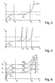
- the curve in time of the current flowing through the electromagnet, the piston of which is initially held by the coaxial spring load substantially comprises three parts: a first part C1 from to (instant at which the driving device begins to make the current i(t) flow through the electromagnet) up to t P (instant at which the current i(t) finally overcomes the initial resistance of the spring load), wherein the piston and the cap remain motionless; a second part C2 from t P (instant at which the piston begins to move) up to t F (instant at which the piston reaches the stop, i.e.
- the current i(t) grows in an exponential way with a time constant that is typical of the same magnet. Since the traction force is directly proportional to the current i(t), during the second part C2 of the curve of the current, at the instant t F the latter arrives at overcoming all the counteracting operating pressure, allowing the cap to make the whole travel. Therefore, the duration of the second part C2, equal to (t F - t P ), is proportional to pressure: the longer the necessary time is, the higher the pressure is, and vice versa.
- the system is capable to know, depending on the time that is detected as necessary to the current i(t) for exponentially increasing by V/R starting from the value i(t P ), how high the operating pressure is.
- the driving device may interrupt the current to the electromagnet and it may again set for a new cycle, causing the piston to return to its starting position by means of the traction of the loaded spring.
- Figures 3 and 4 make clear the curve of the current i(t), the pulse length, and the cap travel at operating pressures of 0 KPa (0 bar) and 1000 KPa (10 bar), respectively.
- the travel is represented with a definition of two tenth of millimetre per square.
- the inventor has further developed the driving device on the basis of the fact that, even when the circuit electrical constants vary (e.g. because of a temperature variation), since the electromagnet is very "air-gapped", the shape of the curve of the current i(t) always comprises characteristic points subdividing the same in a recognisable way, i.e. in a detectable way, into the three afore mentioned parts C1, C2, and C3.
- the three current curves have reached their respective value necessary to overcome the initial resistance of the spring load, they all continue with a second part C2, C2', and C2" of exponential increase from t P up to t F (instant at which the piston reaches the stop, i.e. it arrives at beat), wherein the instant t F is the same instant (in the hypothesis that the operating counteracting pressure is the same for the three curves).
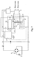
- FIG. 7 shows a schematic circuit diagram of the preferred embodiment of the driving device according to the invention, wherein, in particular, the power electronic switches are represented by simple on-off switches.
- the device according to the invention is connected to the mains 1 through a rectifier bridge 2 and a blocking diode D0 (preventing reverse currents from occurring), the output voltage of which is stabilised by the capacitor C1 and provided, after a resistor R1, on a power supply terminal MA.
- a first power switch S1 is connected between the output terminal PO of a primary winding 3 of the electromagnet 4 and the circuit ground GC.
- a second power switch S2 is connected between the power supply terminal MA and a terminal PI', connected to the input terminal PI of the primary winding 3 of the electromagnet 4 through a resistance compensating electronic control stage 10, the functionality of which will be illustrated below.
- a second diode D1 is connected between the terminal PO and the positive node PN of the stabilising capacitor C1, before the resistor R1, with polarity such that it allows current to flow from the terminal PO to the positive node PN.
- a third diode D2 is connected between the circuit ground GC and the terminal PI', with polarity such that it allows current to flow from the circuit ground GC to the terminal PI'.
- the second and the third diodes D2 and D3 perform the same functions of the similar diodes of the control device that is subject matter of the Italian Patent No. IT1315957 .
- a first control logic unit 6 not galvanically insulated, controls the operation of power switches S1 and S2, it controls the value of the compensating resistance of stage 10, and detects the power supply current flowing through the primary winding 3 of the electromagnet 4, through measuring the voltage on the resistor R1. Moreover, the first control logic unit 6 is connected to a regulation potentiometer P1, adjustable by an operator for indicating the desired capacity of the electromagnetic pump. The power supply necessary to the operation of the first control logic unit 6 is provided by a suitable shunt PP of the primary winding 3 of the electromagnet 4.
- the device further comprises a second control logic unit 7, capable to communicate (in reception and/or in transmission) through digital and/or analog signals with external devices.
- the second control logic unit 7 is capable to further communicate with the first control logic unit 6 through a galvanic insulation unit 8.
- the power supply necessary to the operation of the second control logic unit 7 is provided by a suitable secondary winding 5 of the electromagnet 4.
- the electromagnet 4 is provided with a moving element 9 capable to be attracted within the same electromagnet by the current flowing through the primary winding 3.
- the first control logic unit 6 may adjust the electromagnetic pump capacity, limiting the travel of the piston 9, by simply giving current to the electromagnet only for a portion of the second part C2 of the current curve shown in Figure 2 .
- the device according to the invention replaces the mechanical regulation of presently available adjustable capacity electromagnetic pumps with a wholly electronic, extremely reliable, precise, and inexpensive system.
- the first control logic unit 6 is capable to adapt the driving and capacity regulation in the case where the operating counteracting pressure varies. In fact, by reducing the time of electromagnet current supply as described (for reducing the piston travel in a completely electronic way), the current curve is prevented from reaching the instant t F of stop of the piston 9, not obtaining the check of the instant operating counteracting pressure that, e.g. due to equipment reasons, could vary.
- the first control logic unit 6 after a (either predefined or adjustable) number of strokes of the piston 9 with reduced travel (on the basis of the indication of the potentiometer P1), cyclically carries out a "calibration" driving with which it gives current to the primary winding 3 of the electromagnet 4 up to make the piston 9 reach the stop beat.
- the first control logic unit 6 is capable to detect with continuity the time (t F - t P ) necessary to the piston for making the whole travel and, as a consequence, the value of the operating counteracting pressure, so as to vary the driving of the electromagnet 4 in order to adapt the capacity regulation to the variations of the operating counteracting pressure.
- Figure 8 shows the estimated curve F S and the measured curve F M of the capacity (assuming that the piston always arrives at stop) as a function of the equipment pressure for a specific membrane.
- the first control logic unit 6 is provided with an internal memory storing a (preferably updatable) look-up table wherein, a value of capacity F corresponds to each value of pressure P. Therefore, by cyclically detecting the counteracting operating pressure P as described before, the first control logic unit 6 may simply access the memory and it may read which is the pump capacity for driving of stop of the piston 9, so as to adapt the driving of the electromagnet 4 to the elastic coefficient of the membrane.
- the memory of the first control logic unit 6 could store different look-up tables depending on the viscosity of the liquid to let into the external circuit, the value of which causes a corresponding variation in the pump capacity, such viscosity value being able to be set by an operator.
- the memory could store different look-up tables depending on the ageing of the used membrane.
- the first control logic unit 6 during the rest phases (i.e. between one stroke and the next one), injects a current into the primary winding 3 lower to the value necessary for producing the attraction of the piston 9 and it measures a voltage drop across the same primary winding 3 (e.g. at terminal PP). Afterwards, it calculates the variation of the resistance of the primary winding 3 (due to the temperature variation) and it modifies the value of the series resistance of the stage 10 for compensating such variation.
- the circuit electrical constants of the electromagnet 4 would remain constant and, consequently, there would be no variation of the curve of the current i(t) through the primary winding 3 as temperature varies, as instead shown in Figure 6 . Therefore, the first control logic unit 6 could detect the operating counteracting pressure by determining the time elapsed since any instant (assumed as reference instant) of the first part C1 of the curve of Figure 5 , even the initial instant to at which the current i(t) begins to flow through the electromagnet 4 (i.e. since the instant at which the current has zero value), up to the stop instant t F .
- the stage 10 with a series resistance is purely exemplary, since in other embodiments of the device according to the invention the first control logic unit 6 may modify through software the series resistance of the current generator that in turn supplies the electromagnet 4. Moreover, such compensation may be obtained by means of any other device, such as for instance one or more negative temperature coefficient (NTC) resistors.
- NTC negative temperature coefficient
- the driving method adopted by the device according to the invention is extremely precise, providing a better dosage uniformity: in fact, by reducing the travel it is possible to significantly increase the number of strokes per time unit.
- the device according to the invention allows to always dose the same quantity of product, while in the other presently available apparatuses at equipment pressures lower than the calibration one quantities of product much larger than necessary are dosed with considerable waste and greater pollution.
- the driving method and the device according to the invention allow a better uniformity of capacity among apparatuses of the same family, since in phase of burn-in or ageing the device may learn the quantity of travel necessary for reaching the rating capacity.
- the cap travel reduction occurs by stopping the advance of the same cap, instead of moving the advance origin, as it is in present mechanical control come systems. Therefore, the injected liquid volume will be always directly proportional to the forward movement of the cap and not to the residual movement as in the mechanical case.
- the driving method and the device according to the invention allow a better dosage of viscous liquids, by simply taking account in the calculation parameters used by the driving device of one or more corrective factors depending on the viscosity, i.e. by holding the cap in the position for reaching the required capacity for a longer time so that the liquid has enough time to flow.
Landscapes
- Engineering & Computer Science (AREA)
- Mechanical Engineering (AREA)
- General Engineering & Computer Science (AREA)
- Electromagnetic Pumps, Or The Like (AREA)
- Control Of The Air-Fuel Ratio Of Carburetors (AREA)
- Infusion, Injection, And Reservoir Apparatuses (AREA)
- Control Of Positive-Displacement Pumps (AREA)
Claims (31)
- Elektromagnetische Dosierpumpe umfassend einen arbeitenden Elektromagneten (4), welcher durch eine Antriebseinrichtung gesteuert wird, wobei der Elektromagnet (4) eine Primärwicklung (3) aufweist, die von einem Aktivierungsstrom durchflossen werden kann, sowie ein sich bewegendes Element (9), welches innerhalb der Primärwicklung (3) angezogen werden kann, wenn der Aktivierungsstrom höher als ein erster Schwellwert ist, so dass eine Flüssigkeitsdosis in einen externen hydraulischen Kreislauf entlassen wird, in Abhängigkeit von dem Arbeitsweg des sich bewegenden Elementes (9), wobei die Einrichtung eine zur Steuerung des Aktivierungsstroms geeignete Steuerlogikeinheit (6) umfasst, wobei die Steuerlogikeinheit (6) geeignet ist, den Aktivierungsstrom zu erfassen, um den Aktivierungsstrom an die Primärwicklung (3) zu liefern bis der Aktivierungsstrom einen zweiten Schwellwert annimmt, der von einem Wert der in den externen hydraulischen Kreislauf zu entlassenden Flüssigkeitsdosis abhängt, und welcher höher ist als der erste Schwellwert und nicht höher ist als ein dritter Schwellwert, entsprechend dem das sich bewegende Element (9) einen Halt erreicht, wobei die Pumpe dadurch gekennzeichnet ist, dass die Steuerlogikeinheit (6) den zweiten Schwellwert bestimmt als Summe eines vierten Schwellwerts, welcher zu einem Zeitpunkt (t0, tP), der nach einem konstanten Intervall, welches nicht kürzer ist als 0, auf einen Zeitpunkt (t0), in dem der Aktivierungsstrom durch die Primärwicklung (3) zu fließen beginnt, folgt und dem Zeitpunkt (tF), bei welchem der Aktivierungsstrom den dritten Schwellwert annimmt, vorausgeht, erfasst wird, mit einem Betrag, der nicht größer als die Differenz (Δ, Δ', Δ") zwischen dem dritten Schwellwert und dem vierten Schwellwert ist, wobei dieser Betrag von einem Wert der Flüssigkeitsdosis abhängt, welche in den externen hydraulischen Kreislauf zu entlassen ist.
- Pumpe gemäß Anspruch 1, dadurch gekennzeichnet, dass der vierte Schwellwert gleich dem ersten Schwellwert ist, wobei die Steuerlogikeinheit (6) den zweiten Schwellwert bestimmt als die Summe des ersten Schwellwerts, welcher erfasst wird zu einem Zeitpunkt (tP), der nach einem Intervall (tP-t0) auf den Zeitpunkt (t0), in welchem der Aktivierungsstrom durch die Primärwicklung (3) zu fließen beginnt, folgt, mit einem Betrag, welcher nicht größer ist als die Differenz (Δ, Δ', Δ'') zwischen dem dritten Schwellwert und dem ersten Schwellwert, wobei der Betrag von einem Wert der Flüssigkeitsdosis abhängt, welche in den externen hydraulischen Kreislauf entlassen werden soll.
- Pumpe gemäß Anspruch 1 oder 2, dadurch gekennzeichnet, dass die Antriebseinrichtung ferner elektronische Mittel (10) zum Kompensieren von Widerstandsvariationen der Primärwicklung (3) aufweist, welche durch die Steuerlogikeinheit (6) gesteuert werden, wobei die Steuerlogikeinheit (6) geeignet ist, wenn sie nicht den Aktivierungsstrom liefert, an die Primärwicklung (3) einen Messstrom zu liefern, welcher niedriger als der erste Schwellwert ist, und einen Spannungsabfall über die Primärwicklung (3) zu messen, um zu bestimmen, ob sich der Widerstand der Primärwicklung (3) verändert hat, und in diesem Fall, das elektronischen Kompensationsmittel (10) zum Kompensieren einer solchen Widerstandsvariation zu steuern.
- Pumpe gemäß Anspruch 3, dadurch gekennzeichnet, dass der vierte Schwellwert gleich 0 ist, wobei die Steuerlogikeinheit (6) den zweiten Schwellwert bestimmt als gleich einem Betrag, welcher nicht größer ist als der dritte Schwellwert, wobei der Betrag von einem Wert der in den externen hydraulischen Kreislauf zu entlassenden Flüssigkeitsdosis abhängt.
- Pumpe gemäß einem der vorhergehenden Ansprüche, dadurch gekennzeichnet, dass die Steuerlogikeinheit (6) zyklisch den Aktivierungsstrom an die Primärwicklung (3) liefert, bis der Aktivierungsstrom den dritten Schwellwert annimmt, entsprechend dem das sich bewegende Element (9) den Halt erreicht.
- Pumpe gemäß Anspruch 5, dadurch gekennzeichnet, dass, wenn die Steuerlogikeinheit (6) den Aktivierungsstrom an die Primärwicklung (3) liefert, bis der Aktivierungsstrom den dritten Schwellwert annimmt, die Steuerlogikeinheit (6) einen Druck feststellt, welcher von dem externen hydraulischen Kreislauf auf die Pumpe ausgeübt wird, als proportional zu einem Zeitintervall, welches von einem Referenzzeitpunkt, der im Bereich zwischen dem Zeitpunkt (t0), in dem der Aktivierungsstrom durch die Primärwicklung (3) zu fließen beginnt, und dem Zeitpunkt (tF), in welchem der Aktivierungsstrom den dritten Schwellwert annimmt, liegt, vergeht bis zu dem Zeitpunkt (tF), bei welchem der Aktivierungsstrom den dritten Schwellwert annimmt.
- Pumpe gemäß Anspruch 6, dadurch gekennzeichnet, dass der Referenzzeitpunkt gleich dem Zeitpunkt (t0) ist, bei welchem der Aktivierungsstrom durch die Primärwicklung (3) zu fließen beginnt, oder gleich dem Zeitpunkt (tP), bei welchem der Aktivierungsstrom den ersten Schwellwert annimmt.
- Pumpe gemäß Anspruch 6 oder 7, dadurch gekennzeichnet, dass die Steuerlogikeinheit (6) den zweiten Schwellwert als eine Funktion des festgestellten Werts des externen Drucks berechnet.
- Pumpe gemäß Anspruch 6 oder 7, dadurch gekennzeichnet, dass die Steuerlogikeinheit (6) mit Speichermitteln ausgestattet ist, welche wenigstens eine, vorzugsweise aktualisierbare Nachschlagtabelle speichert, auf welche die Steuerlogikeinheit (6) zum Lesen des zweiten Schwellwerts als einer Funktion des festgestellten Werts des externen Drucks zugreift.
- Pumpe gemäß einem der vorhergehenden Ansprüche, dadurch gekennzeichnet, dass sie eine Membran mit einem elastischen Koeffizienten aufweist, wobei die Steuerlogikeinheit (6) den zweiten Schwellwert als eine Funktion des elastischen Koeffizienten der Membran bestimmt.
- Pumpe gemäß Anspruch 10, dadurch gekennzeichnet, dass die Steuerlogikeinheit (6) mit Speichermitteln ausgestattet ist, welche wenigstens eine, vorzugsweise aktualisierbare, Nachschlagtabelle speichern, auf welche die Steuerlogikeinheit (6) zugreift, um den zweiten Schwellwert als eine Funktion des elastischen Koeffizienten der Membran zu lesen.
- Pumpe gemäß einem der vorhergehenden Ansprüche, dadurch gekennzeichnet, dass die Antriebseinrichtung ferner ein erstes Auswahlmittel (P1) umfasst, welches mit der Steuerlogikeinheit (6) verbunden ist, und geeignet ist, den Wert der in den externen hydraulischen Kreislauf zu entlassenden Flüssigkeitsdosis auszuwählen.
- Pumpe gemäß einem der vorhergehenden Ansprüche, dadurch gekennzeichnet, dass die Antriebseinrichtung ferner ein zweites Auswahlmittel umfasst, welches mit der Steuerlogikeinheit (6) verbunden ist, und welches geeignet ist, eine Viskosität der in den externen Kreislauf zu entlassenden Flüssigkeit auszuwählen.
- Pumpe gemäß Anspruch 13, dadurch gekennzeichnet, dass die Steuerlogikeinheit (6) den zweiten Schwellwert als Funktion der ausgewählten Viskosität der in den externen Kreislauf zu entlassenden Flüssigkeit berechnet.
- Pumpe gemäß Anspruch 13, dadurch gekennzeichnet, dass die Steuerlogikeinheit (6) mit einem Speichermittel ausgestattet ist, welches wenigstens eine, vorzugsweise aktualisierbare, Nachschlagtabelle speichert, auf welche die Steuerlogikeinheit (6) zugreift, um den zweiten Schwellwert als eine Funktion der ausgewählten Viskosität der in den externen Kreislauf zu entlassenden Flüssigkeit zu lesen.
- Vorrichtung zum Antreiben eines Elektromagneten, umfassend eine Steuerlogikeinheit (6), dadurch gekennzeichnet, dass die Antriebsvorrichtung geeignet ist, als Antriebseinrichtung einer elektromagnetischen Dosierpumpe gemäß einem der Ansprüche 1-15 betrieben zu werden.
- Verfahren zum Betreiben eines Elektromagneten (4) zum Betreiben einer Pumpe, wobei der Elektromagnet (4) eine Primärwicklung (3) umfasst, welche von einem Aktivierungsstrom durchflossen werden kann, sowie ein sich bewegendes Element (9), welches innerhalb der Primärwicklung (3) angezogen werden kann, wenn der Aktivierungsstrom höher als ein erster Schwellwert ist, so dass als eine Funktion des Arbeitsweges des sich bewegenden Elementes (9) eine Flüssigkeitsdosis in einen externen hydraulischen Kreislauf entlassen wird, wobei das Verfahren die folgenden Schritte umfasst:A. Erfassen des Aktivierungsstroms;B. Liefern des Aktivierungsstroms an die Primärwicklung (3) bis der Aktivierungsstrom einen zweiten Schwellwert annimmt, der von einem Wert der in den externen hydraulischen Kreislauf zu entlassenden Flüssigkeitsdosis abhängt und größer ist als der erste Schwellwert und nicht größer ist als ein dritter Schwellwert, entsprechend dem das sich bewegende Element (9) einen Halt erreicht;wobei das Verfahren dadurch gekennzeichnet ist, dass in Schritt B der zweite Schwellwert bestimmt wird als die Summe eines vierten Schwellwerts, welcher in einem Zeitpunkt (t0, tP) erfasst wird, der nach einem konstanten Intervall, das nicht kleiner als 0 ist, auf den Zeitpunkt (t0), in dem der Aktivierungsstrom durch die Primärwicklung (3) zu fließen beginnt, folgt und dem Zeitpunkt (tF), in dem der Aktivierungsstrom den dritten Schwellwert annimmt, vorausgeht, mit einem Betrag, der nicht größer als die Differenz (Δ, Δ', Δ'') zwischen dem dritten Schwellwert und dem vierten Schwellwert ist, wobei der Betrag von einem Wert der in den externen hydraulischen Kreislauf zu entlassenden Flüssigkeitsdosis abhängt.
- Verfahren gemäß Anspruch 17, dadurch gekennzeichnet, dass der vierte Schwellwert gleich dem ersten Schwellwert ist, wobei in Schritt B der zweite Schwellwert bestimmt wird als die Summe des ersten Schwellwerts, welcher zu dem Zeitpunkt (tP), der nach einem konstanten Intervall (tP-t0), auf den Punkt (t0), bei welchem der Aktivierungsstrom durch die Primärwicklung (3) zu fließen beginnt, folgt, mit einem Betrag, der nicht größer ist als die Differenz (Δ, Δ', Δ'') zwischen dem dritten Schwellwert und dem ersten Schwellwert, wobei der Betrag von dem Wert der in den externen hydraulischen Kreislauf zu entlassenden Flüssigkeitsdosis abhängt.
- Verfahren gemäß Anspruch 17 oder 18, dadurch gekennzeichnet, dass es ferner die folgenden Schritte umfasst:C. Liefern eines Messstroms, welcher geringer ist als der erste Schwellwert, an die Primärwicklung (3),D. Messen eines Spannungsabfalls über die Primärwicklung (3), um zu bestimmen, ob sich der Widerstand der Primärwicklung (3) verändert hat und, in diesem Fall, zum Kompensieren einer solchen Widerstandsvariation.
- Verfahren gemäß Anspruch 19, dadurch gekennzeichnet, dass der vierte Schwellwert gleich 0 ist, wobei in Schritt B der zweite Schwellwert bestimmt wird als gleich einem Betrag, der nicht größer ist als der dritte Schwellwert, wobei der Betrag von einem Wert der in den externen hydraulischen Kreislauf zu entlassenden Flüssigkeitsdosis abhängt.
- Verfahren gemäß einem der Ansprüche 17 bis 20, dadurch gekennzeichnet, dass es ferner den folgenden Schritt umfasst:E. zyklisches Liefern des Aktivierungsstroms an die Primärwicklung (3) bis der Aktivierungsstrom den dritten Schwellwert annimmt, entsprechend dem das sich bewegende Element (9) einen Halt erreicht.
- Verfahren gemäß Anspruch 21, dadurch gekennzeichnet, dass in Schritt E ein von dem externen hydraulischen Kreislauf auf die Pumpe ausgeübter Druck als proportional zu dem Zeitintervall bestimmt wird, welches von einem Referenzzeitpunkt, der im Bereich zwischen dem Zeitpunkt (t0), in welchem der Aktivierungsstrom durch die Primärwicklung (3) zu fließen beginnt, und dem Zeitpunkt (tF), in welchem der Aktivierungsstrom den dritten Schwellwert annimmt, liegt, vergeht bis zu dem Zeitpunkt (tF), bei welchem der Aktivierungsstrom den dritten Schwellwert annimmt.
- Verfahren gemäß Anspruch 22, dadurch gekennzeichnet, dass der Referenzzeitpunkt gleich dem Zeitpunkt (t0) ist, in welchem der Aktivierungsstrom durch die Primärwicklung (3) zu fließen beginnt, oder gleich dem Zeitpunkt (tP), in welchem der Aktivierungsstrom den ersten Schwellwert annimmt.
- Verfahren gemäß Anspruch 22 oder 23, dadurch gekennzeichnet, dass in Schritt B der zweite Schwellwert als Funktion des externen Druckwerts, welcher in Schritt E bestimmt wurde, berechnet wird.
- Verfahren gemäß Anspruch 22 oder 23, dadurch gekennzeichnet, dass der zweite Schwellwert in Schritt B aus einem Speichermittel an wenigstens einem Ort in Abhängigkeit von dem in Schritt E bestimmten externen Druckwerts gelesen wird.
- Verfahren gemäß einem der Ansprüche 17 bis 25, dadurch gekennzeichnet, dass die Pumpe eine Membran mit einem Elastizitätskoeffizienten aufweist, und dass der zweite Schwellwert in Schritt B bestimmt wird als Funktion des Elastizitätskoeffizienten der Membran.
- Verfahren gemäß Anspruch 26, dadurch gekennzeichnet, dass der zweite Schwellwert in Schritt B aus einem Speichermittel an wenigstens einem Ort in Abhängigkeit von dem Elastizitätskoeffizienten der Membran gelesen wird.
- Verfahren gemäß einem der Ansprüche 17 bis 27, dadurch gekennzeichnet, dass es ferner den folgenden Schritt umfasst:F. Auswählen des Werts der in den externen hydraulischen Kreislauf zu entlassenden Flüssigkeitsdosis.
- Verfahren gemäß einem der Ansprüche 17 bis 28, dadurch gekennzeichnet, dass es ferner den folgenden Schritt umfasst:G. Auswählen einer Viskosität der in den externen Kreislauf zu entlassenden Flüssigkeit.
- Verfahren gemäß Anspruch 29, dadurch gekennzeichnet, dass in Schritt B der zweite Schwellwert berechnet wird als eine Funktion der in Schritt G ausgewählten Flüssigkeitsviskosität.
- Verfahren gemäß Anspruch 29, dadurch gekennzeichnet, dass der zweite Schwellwert in Schritt B aus einem Speichermittel an wenigstens einem Ort in Abhängigkeit von der in Schritt G ausgewählten Flüssigkeitsviskosität gelesen wird.
Applications Claiming Priority (2)
| Application Number | Priority Date | Filing Date | Title |
|---|---|---|---|
| IT000373A ITRM20050373A1 (it) | 2005-07-13 | 2005-07-13 | Dispositivo di pilotaggio di un elettromagnete di azionamento di una pompa, e relativa pompa elettromagnetica dosatrice. |
| PCT/IT2006/000517 WO2007007365A1 (en) | 2005-07-13 | 2006-07-07 | Device for driving an electromagnetic pump and related electromagnetic dosing pump |
Publications (2)
| Publication Number | Publication Date |
|---|---|
| EP1904745A1 EP1904745A1 (de) | 2008-04-02 |
| EP1904745B1 true EP1904745B1 (de) | 2009-10-21 |
Family
ID=36997902
Family Applications (1)
| Application Number | Title | Priority Date | Filing Date |
|---|---|---|---|
| EP06766377A Active EP1904745B1 (de) | 2005-07-13 | 2006-07-07 | Vorrichtung zum antrieb einer elektromagnetischen pumpe und verwandte elektromagnetische dosierpumpe |
Country Status (10)
| Country | Link |
|---|---|
| US (1) | US8257052B2 (de) |
| EP (1) | EP1904745B1 (de) |
| CN (1) | CN101228353B (de) |
| AT (1) | ATE446447T1 (de) |
| CA (1) | CA2614325C (de) |
| DE (1) | DE602006009942D1 (de) |
| DK (1) | DK1904745T3 (de) |
| ES (1) | ES2335528T3 (de) |
| IT (1) | ITRM20050373A1 (de) |
| WO (1) | WO2007007365A1 (de) |
Families Citing this family (7)
| Publication number | Priority date | Publication date | Assignee | Title |
|---|---|---|---|---|
| IT1398982B1 (it) | 2010-03-17 | 2013-03-28 | Etatron D S Spa | Dispositivo di controllo della corsa del pistone di una pompa dosatrice per la regolazione automatica della portata ad alto rendimento. |
| EP2572105B1 (de) * | 2010-05-18 | 2019-01-09 | Aktiebolaget Electrolux | Batteriebetriebene dosiervorrichtung |
| DE102011050018A1 (de) * | 2011-04-29 | 2012-10-31 | Allweiler Gmbh | Pumpen-System |
| DE102012211875A1 (de) * | 2012-07-06 | 2014-01-09 | Robert Bosch Gmbh | Fördermodul für einen Betriebs-/Hilfsstoff zur Nachbehandlung von Abgas |
| US10859592B2 (en) * | 2017-01-31 | 2020-12-08 | Tecan Trading Ag | Method of aspirating by pipetting and pipetting apparatus |
| IT201700103749A1 (it) * | 2017-09-15 | 2019-03-15 | Robertshaw S R L | Pompa e relativo metodo di controllo |
| FR3092146B1 (fr) * | 2019-01-24 | 2020-12-25 | Continental Automotive | Procédé de gestion d’une pompe à piston pour moteur thermique |
Family Cites Families (14)
| Publication number | Priority date | Publication date | Assignee | Title |
|---|---|---|---|---|
| DE1813638A1 (de) * | 1968-12-10 | 1970-06-25 | Bosch Gmbh Robert | Elektrischer Antriebsmotor fuer Scheibenwischer,insbesondere von Kraftfahrzeugen |
| US3610782A (en) * | 1969-10-06 | 1971-10-05 | Precision Control Products Cor | Controlled pump |
| CN1225157A (zh) * | 1996-07-15 | 1999-08-04 | 西拉克集团公司 | 电磁控制的计量泵 |
| JPH10230539A (ja) * | 1997-02-19 | 1998-09-02 | Mitsubishi Heavy Ind Ltd | 比例電磁制御弁の作動特性測定方法,油圧シリンダの作動制御方法および比例電磁制御弁の作動特性修正方法 |
| JPH11182444A (ja) * | 1997-10-17 | 1999-07-06 | Takumina:Kk | ソレノイド駆動ポンプの制御回路 |
| JP3899648B2 (ja) * | 1998-03-13 | 2007-03-28 | 株式会社明電舎 | 多重巻線電動機の制御方法 |
| US6264432B1 (en) * | 1999-09-01 | 2001-07-24 | Liquid Metronics Incorporated | Method and apparatus for controlling a pump |
| US6503062B1 (en) * | 2000-07-10 | 2003-01-07 | Deka Products Limited Partnership | Method for regulating fluid pump pressure |
| IT1315957B1 (it) | 2000-07-12 | 2003-03-26 | Seko Italia Spa | Perfezionato dispositivo di controllo per elettromagneti e simili, inparticolare per l'azionamento di pompe di dosaggio di liquidi. |
| US6595756B2 (en) * | 2001-09-07 | 2003-07-22 | Medtronic Minimed, Inc. | Electronic control system and process for electromagnetic pump |
| US7361155B2 (en) * | 2003-09-16 | 2008-04-22 | Therafuse, Inc. | Compensating liquid delivery system and method |
| ITRM20040371A1 (it) | 2004-07-21 | 2004-10-21 | Seko Italia S P A | Dispositivo di pilotaggio di un elettromagnete, in particolare per l'azionamento di pompe. |
| JP4960038B2 (ja) * | 2006-08-09 | 2012-06-27 | オークマ株式会社 | パラレルメカニズム機械の制御方法及び制御装置 |
| US8007247B2 (en) * | 2007-05-22 | 2011-08-30 | Medtronic, Inc. | End of stroke detection for electromagnetic pump |
-
2005
- 2005-07-13 IT IT000373A patent/ITRM20050373A1/it unknown
-
2006
- 2006-07-07 AT AT06766377T patent/ATE446447T1/de active
- 2006-07-07 CN CN2006800253032A patent/CN101228353B/zh active Active
- 2006-07-07 US US11/995,470 patent/US8257052B2/en active Active
- 2006-07-07 DK DK06766377.3T patent/DK1904745T3/da active
- 2006-07-07 EP EP06766377A patent/EP1904745B1/de active Active
- 2006-07-07 CA CA2614325A patent/CA2614325C/en active Active
- 2006-07-07 DE DE602006009942T patent/DE602006009942D1/de active Active
- 2006-07-07 ES ES06766377T patent/ES2335528T3/es active Active
- 2006-07-07 WO PCT/IT2006/000517 patent/WO2007007365A1/en not_active Ceased
Also Published As
| Publication number | Publication date |
|---|---|
| CN101228353A (zh) | 2008-07-23 |
| US20080226464A1 (en) | 2008-09-18 |
| DE602006009942D1 (de) | 2009-12-03 |
| EP1904745A1 (de) | 2008-04-02 |
| CN101228353B (zh) | 2012-05-16 |
| WO2007007365A1 (en) | 2007-01-18 |
| CA2614325C (en) | 2011-04-05 |
| US8257052B2 (en) | 2012-09-04 |
| DK1904745T3 (da) | 2010-03-08 |
| ITRM20050373A1 (it) | 2007-01-14 |
| CA2614325A1 (en) | 2007-01-18 |
| ES2335528T3 (es) | 2010-03-29 |
| ATE446447T1 (de) | 2009-11-15 |
Similar Documents
| Publication | Publication Date | Title |
|---|---|---|
| EP2547909B1 (de) | Dosierpumpe mit steuerungsvorrichtung für den kolbenhub | |
| US6895997B2 (en) | System for determining positions of a control element of an electrically driven actuator | |
| EP1904745B1 (de) | Vorrichtung zum antrieb einer elektromagnetischen pumpe und verwandte elektromagnetische dosierpumpe | |
| CN103026064B (zh) | 电池供电的定量装置 | |
| US6271618B1 (en) | Method and configuration for driving a capacitive actuator | |
| US6234122B1 (en) | Method for driving an electromagnetic actuator for operating a gas change valve | |
| WO1993011369A1 (en) | Method and apparatus for determining the position of an armature in an electromagnetic actuator | |
| CN101164125A (zh) | 电磁促动器上的无传感器位置识别 | |
| CN107978416B (zh) | 确定电磁执行器的可运动电枢的位置的方法和电路装置 | |
| US9448260B2 (en) | Ascertaining the ballistic trajectory of an electromagnetically driven armature of a coil actuator | |
| CN107949892A (zh) | 用于确定电磁执行器的能够移动的电枢的位置的方法和电路装置 | |
| US20230279965A1 (en) | Method for determining the position of an armature of an electromagnet and fluid system | |
| US7159506B2 (en) | State detecting device for load element receiving load of working fluid and state detecting device for fluid pressure control circuit | |
| US11442478B2 (en) | Pressure control device | |
| JP2633005B2 (ja) | 定流量ポンプ用流量計 | |
| WO2012078097A1 (en) | Comfort warming control system | |
| KR101771802B1 (ko) | 솔레노이드 작동체를 제어하는 방법 및 디바이스 | |
| CN113056719B (zh) | 用于控制拉杆磁铁的方法和装置 | |
| US7542261B2 (en) | Device for driving and electromagnet, particularly for operating pumps | |
| US20240125314A1 (en) | Process for sensorless detection of stroke execution in a magnetic pump | |
| WO2016173774A1 (en) | Urea dosing method for vehicle exhaust systems | |
| WO2006029947A1 (de) | Vorrichtung und verfahren zur einer prozessgrösse | |
| KR20140057872A (ko) | 솔레노이드 과통전을 방지하기 위한 솔레노이드 제어 장치 및 방법 |
Legal Events
| Date | Code | Title | Description |
|---|---|---|---|
| PUAI | Public reference made under article 153(3) epc to a published international application that has entered the european phase |
Free format text: ORIGINAL CODE: 0009012 |
|
| 17P | Request for examination filed |
Effective date: 20080115 |
|
| AK | Designated contracting states |
Kind code of ref document: A1 Designated state(s): AT BE BG CH CY CZ DE DK EE ES FI FR GB GR HU IE IS IT LI LT LU LV MC NL PL PT RO SE SI SK TR |
|
| DAX | Request for extension of the european patent (deleted) | ||
| GRAP | Despatch of communication of intention to grant a patent |
Free format text: ORIGINAL CODE: EPIDOSNIGR1 |
|
| GRAS | Grant fee paid |
Free format text: ORIGINAL CODE: EPIDOSNIGR3 |
|
| RAP1 | Party data changed (applicant data changed or rights of an application transferred) |
Owner name: SEKO S.P.A. |
|
| GRAA | (expected) grant |
Free format text: ORIGINAL CODE: 0009210 |
|
| AK | Designated contracting states |
Kind code of ref document: B1 Designated state(s): AT BE BG CH CY CZ DE DK EE ES FI FR GB GR HU IE IS IT LI LT LU LV MC NL PL PT RO SE SI SK TR |
|
| REG | Reference to a national code |
Ref country code: GB Ref legal event code: FG4D |
|
| REG | Reference to a national code |
Ref country code: CH Ref legal event code: EP |
|
| REG | Reference to a national code |
Ref country code: IE Ref legal event code: FG4D |
|
| REF | Corresponds to: |
Ref document number: 602006009942 Country of ref document: DE Date of ref document: 20091203 Kind code of ref document: P |
|
| REG | Reference to a national code |
Ref country code: DK Ref legal event code: T3 |
|
| LTIE | Lt: invalidation of european patent or patent extension |
Effective date: 20091021 |
|
| REG | Reference to a national code |
Ref country code: ES Ref legal event code: FG2A Ref document number: 2335528 Country of ref document: ES Kind code of ref document: T3 |
|
| NLV1 | Nl: lapsed or annulled due to failure to fulfill the requirements of art. 29p and 29m of the patents act | ||
| PG25 | Lapsed in a contracting state [announced via postgrant information from national office to epo] |
Ref country code: FI Free format text: LAPSE BECAUSE OF FAILURE TO SUBMIT A TRANSLATION OF THE DESCRIPTION OR TO PAY THE FEE WITHIN THE PRESCRIBED TIME-LIMIT Effective date: 20091021 Ref country code: PT Free format text: LAPSE BECAUSE OF FAILURE TO SUBMIT A TRANSLATION OF THE DESCRIPTION OR TO PAY THE FEE WITHIN THE PRESCRIBED TIME-LIMIT Effective date: 20100222 Ref country code: SE Free format text: LAPSE BECAUSE OF FAILURE TO SUBMIT A TRANSLATION OF THE DESCRIPTION OR TO PAY THE FEE WITHIN THE PRESCRIBED TIME-LIMIT Effective date: 20091021 Ref country code: IS Free format text: LAPSE BECAUSE OF FAILURE TO SUBMIT A TRANSLATION OF THE DESCRIPTION OR TO PAY THE FEE WITHIN THE PRESCRIBED TIME-LIMIT Effective date: 20100221 Ref country code: LT Free format text: LAPSE BECAUSE OF FAILURE TO SUBMIT A TRANSLATION OF THE DESCRIPTION OR TO PAY THE FEE WITHIN THE PRESCRIBED TIME-LIMIT Effective date: 20091021 |
|
| PG25 | Lapsed in a contracting state [announced via postgrant information from national office to epo] |
Ref country code: SI Free format text: LAPSE BECAUSE OF FAILURE TO SUBMIT A TRANSLATION OF THE DESCRIPTION OR TO PAY THE FEE WITHIN THE PRESCRIBED TIME-LIMIT Effective date: 20091021 Ref country code: CY Free format text: LAPSE BECAUSE OF FAILURE TO SUBMIT A TRANSLATION OF THE DESCRIPTION OR TO PAY THE FEE WITHIN THE PRESCRIBED TIME-LIMIT Effective date: 20091021 Ref country code: LV Free format text: LAPSE BECAUSE OF FAILURE TO SUBMIT A TRANSLATION OF THE DESCRIPTION OR TO PAY THE FEE WITHIN THE PRESCRIBED TIME-LIMIT Effective date: 20091021 Ref country code: PL Free format text: LAPSE BECAUSE OF FAILURE TO SUBMIT A TRANSLATION OF THE DESCRIPTION OR TO PAY THE FEE WITHIN THE PRESCRIBED TIME-LIMIT Effective date: 20091021 |
|
| PG25 | Lapsed in a contracting state [announced via postgrant information from national office to epo] |
Ref country code: BE Free format text: LAPSE BECAUSE OF FAILURE TO SUBMIT A TRANSLATION OF THE DESCRIPTION OR TO PAY THE FEE WITHIN THE PRESCRIBED TIME-LIMIT Effective date: 20091021 |
|
| PG25 | Lapsed in a contracting state [announced via postgrant information from national office to epo] |
Ref country code: EE Free format text: LAPSE BECAUSE OF FAILURE TO SUBMIT A TRANSLATION OF THE DESCRIPTION OR TO PAY THE FEE WITHIN THE PRESCRIBED TIME-LIMIT Effective date: 20091021 Ref country code: BG Free format text: LAPSE BECAUSE OF FAILURE TO SUBMIT A TRANSLATION OF THE DESCRIPTION OR TO PAY THE FEE WITHIN THE PRESCRIBED TIME-LIMIT Effective date: 20100121 Ref country code: RO Free format text: LAPSE BECAUSE OF FAILURE TO SUBMIT A TRANSLATION OF THE DESCRIPTION OR TO PAY THE FEE WITHIN THE PRESCRIBED TIME-LIMIT Effective date: 20091021 |
|
| PLBE | No opposition filed within time limit |
Free format text: ORIGINAL CODE: 0009261 |
|
| STAA | Information on the status of an ep patent application or granted ep patent |
Free format text: STATUS: NO OPPOSITION FILED WITHIN TIME LIMIT |
|
| PG25 | Lapsed in a contracting state [announced via postgrant information from national office to epo] |
Ref country code: SK Free format text: LAPSE BECAUSE OF FAILURE TO SUBMIT A TRANSLATION OF THE DESCRIPTION OR TO PAY THE FEE WITHIN THE PRESCRIBED TIME-LIMIT Effective date: 20091021 Ref country code: CZ Free format text: LAPSE BECAUSE OF FAILURE TO SUBMIT A TRANSLATION OF THE DESCRIPTION OR TO PAY THE FEE WITHIN THE PRESCRIBED TIME-LIMIT Effective date: 20091021 |
|
| 26N | No opposition filed |
Effective date: 20100722 |
|
| PG25 | Lapsed in a contracting state [announced via postgrant information from national office to epo] |
Ref country code: GR Free format text: LAPSE BECAUSE OF FAILURE TO SUBMIT A TRANSLATION OF THE DESCRIPTION OR TO PAY THE FEE WITHIN THE PRESCRIBED TIME-LIMIT Effective date: 20100122 |
|
| REG | Reference to a national code |
Ref country code: CH Ref legal event code: PL |
|
| PG25 | Lapsed in a contracting state [announced via postgrant information from national office to epo] |
Ref country code: CH Free format text: LAPSE BECAUSE OF NON-PAYMENT OF DUE FEES Effective date: 20100731 Ref country code: LI Free format text: LAPSE BECAUSE OF NON-PAYMENT OF DUE FEES Effective date: 20100731 |
|
| PG25 | Lapsed in a contracting state [announced via postgrant information from national office to epo] |
Ref country code: LU Free format text: LAPSE BECAUSE OF NON-PAYMENT OF DUE FEES Effective date: 20100707 Ref country code: HU Free format text: LAPSE BECAUSE OF FAILURE TO SUBMIT A TRANSLATION OF THE DESCRIPTION OR TO PAY THE FEE WITHIN THE PRESCRIBED TIME-LIMIT Effective date: 20100422 Ref country code: NL Free format text: LAPSE BECAUSE OF FAILURE TO SUBMIT A TRANSLATION OF THE DESCRIPTION OR TO PAY THE FEE WITHIN THE PRESCRIBED TIME-LIMIT Effective date: 20091021 |
|
| PG25 | Lapsed in a contracting state [announced via postgrant information from national office to epo] |
Ref country code: TR Free format text: LAPSE BECAUSE OF FAILURE TO SUBMIT A TRANSLATION OF THE DESCRIPTION OR TO PAY THE FEE WITHIN THE PRESCRIBED TIME-LIMIT Effective date: 20091021 |
|
| REG | Reference to a national code |
Ref country code: FR Ref legal event code: PLFP Year of fee payment: 11 |
|
| REG | Reference to a national code |
Ref country code: FR Ref legal event code: PLFP Year of fee payment: 12 |
|
| REG | Reference to a national code |
Ref country code: FR Ref legal event code: PLFP Year of fee payment: 13 |
|
| P01 | Opt-out of the competence of the unified patent court (upc) registered |
Effective date: 20230601 |
|
| PGFP | Annual fee paid to national office [announced via postgrant information from national office to epo] |
Ref country code: DK Payment date: 20240618 Year of fee payment: 19 Ref country code: MC Payment date: 20240618 Year of fee payment: 19 |
|
| PGFP | Annual fee paid to national office [announced via postgrant information from national office to epo] |
Ref country code: DE Payment date: 20240617 Year of fee payment: 19 Ref country code: IE Payment date: 20240722 Year of fee payment: 19 |
|
| PGFP | Annual fee paid to national office [announced via postgrant information from national office to epo] |
Ref country code: GB Payment date: 20240718 Year of fee payment: 19 |
|
| PGFP | Annual fee paid to national office [announced via postgrant information from national office to epo] |
Ref country code: FR Payment date: 20240718 Year of fee payment: 19 |
|
| PGFP | Annual fee paid to national office [announced via postgrant information from national office to epo] |
Ref country code: ES Payment date: 20240801 Year of fee payment: 19 |
|
| PGFP | Annual fee paid to national office [announced via postgrant information from national office to epo] |
Ref country code: AT Payment date: 20240617 Year of fee payment: 19 |
|
| PGFP | Annual fee paid to national office [announced via postgrant information from national office to epo] |
Ref country code: IT Payment date: 20240712 Year of fee payment: 19 |
|
| REG | Reference to a national code |
Ref country code: DE Ref legal event code: R119 Ref document number: 602006009942 Country of ref document: DE |
|
| REG | Reference to a national code |
Ref country code: DK Ref legal event code: EBP Effective date: 20250731 |
|
| REG | Reference to a national code |
Ref country code: AT Ref legal event code: MM01 Ref document number: 446447 Country of ref document: AT Kind code of ref document: T Effective date: 20250707 |
|
| GBPC | Gb: european patent ceased through non-payment of renewal fee |
Effective date: 20250707 |
|
| PG25 | Lapsed in a contracting state [announced via postgrant information from national office to epo] |
Ref country code: GB Free format text: LAPSE BECAUSE OF NON-PAYMENT OF DUE FEES Effective date: 20250707 |
|
| PG25 | Lapsed in a contracting state [announced via postgrant information from national office to epo] |
Ref country code: DE Free format text: LAPSE BECAUSE OF NON-PAYMENT OF DUE FEES Effective date: 20260203 |
|
| PG25 | Lapsed in a contracting state [announced via postgrant information from national office to epo] |
Ref country code: AT Free format text: LAPSE BECAUSE OF NON-PAYMENT OF DUE FEES Effective date: 20250707 |
|
| PG25 | Lapsed in a contracting state [announced via postgrant information from national office to epo] |
Ref country code: FR Free format text: LAPSE BECAUSE OF NON-PAYMENT OF DUE FEES Effective date: 20250731 |