EP1905535A2 - Magasin à outils dans un centre d'usinage à commande numérique et similaires et processus de changement d'outil dans un tel magasin - Google Patents
Magasin à outils dans un centre d'usinage à commande numérique et similaires et processus de changement d'outil dans un tel magasin Download PDFInfo
- Publication number
- EP1905535A2 EP1905535A2 EP07019017A EP07019017A EP1905535A2 EP 1905535 A2 EP1905535 A2 EP 1905535A2 EP 07019017 A EP07019017 A EP 07019017A EP 07019017 A EP07019017 A EP 07019017A EP 1905535 A2 EP1905535 A2 EP 1905535A2
- Authority
- EP
- European Patent Office
- Prior art keywords
- track
- tool
- bush
- warehouse
- bushes
- Prior art date
- Legal status (The legal status is an assumption and is not a legal conclusion. Google has not performed a legal analysis and makes no representation as to the accuracy of the status listed.)
- Granted
Links
Images








Classifications
-
- B—PERFORMING OPERATIONS; TRANSPORTING
- B23—MACHINE TOOLS; METAL-WORKING NOT OTHERWISE PROVIDED FOR
- B23Q—DETAILS, COMPONENTS, OR ACCESSORIES FOR MACHINE TOOLS, e.g. ARRANGEMENTS FOR COPYING OR CONTROLLING; MACHINE TOOLS IN GENERAL CHARACTERISED BY THE CONSTRUCTION OF PARTICULAR DETAILS OR COMPONENTS; COMBINATIONS OR ASSOCIATIONS OF METAL-WORKING MACHINES, NOT DIRECTED TO A PARTICULAR RESULT
- B23Q3/00—Devices holding, supporting, or positioning work or tools, of a kind normally removable from the machine
- B23Q3/155—Arrangements for automatic insertion or removal of tools, e.g. combined with manual handling
- B23Q3/1552—Arrangements for automatic insertion or removal of tools, e.g. combined with manual handling parts of devices for automatically inserting or removing tools
- B23Q3/15526—Storage devices; Drive mechanisms therefor
-
- B—PERFORMING OPERATIONS; TRANSPORTING
- B23—MACHINE TOOLS; METAL-WORKING NOT OTHERWISE PROVIDED FOR
- B23Q—DETAILS, COMPONENTS, OR ACCESSORIES FOR MACHINE TOOLS, e.g. ARRANGEMENTS FOR COPYING OR CONTROLLING; MACHINE TOOLS IN GENERAL CHARACTERISED BY THE CONSTRUCTION OF PARTICULAR DETAILS OR COMPONENTS; COMBINATIONS OR ASSOCIATIONS OF METAL-WORKING MACHINES, NOT DIRECTED TO A PARTICULAR RESULT
- B23Q3/00—Devices holding, supporting, or positioning work or tools, of a kind normally removable from the machine
- B23Q3/155—Arrangements for automatic insertion or removal of tools, e.g. combined with manual handling
- B23Q3/157—Arrangements for automatic insertion or removal of tools, e.g. combined with manual handling of rotary tools
- B23Q3/15713—Arrangements for automatic insertion or removal of tools, e.g. combined with manual handling of rotary tools a transfer device taking a single tool from a storage device and inserting it in a spindle
- B23Q3/1572—Arrangements for automatic insertion or removal of tools, e.g. combined with manual handling of rotary tools a transfer device taking a single tool from a storage device and inserting it in a spindle the storage device comprising rotating or circulating storing means
- B23Q3/15724—Chains or belts
-
- B—PERFORMING OPERATIONS; TRANSPORTING
- B23—MACHINE TOOLS; METAL-WORKING NOT OTHERWISE PROVIDED FOR
- B23Q—DETAILS, COMPONENTS, OR ACCESSORIES FOR MACHINE TOOLS, e.g. ARRANGEMENTS FOR COPYING OR CONTROLLING; MACHINE TOOLS IN GENERAL CHARACTERISED BY THE CONSTRUCTION OF PARTICULAR DETAILS OR COMPONENTS; COMBINATIONS OR ASSOCIATIONS OF METAL-WORKING MACHINES, NOT DIRECTED TO A PARTICULAR RESULT
- B23Q3/00—Devices holding, supporting, or positioning work or tools, of a kind normally removable from the machine
- B23Q3/155—Arrangements for automatic insertion or removal of tools, e.g. combined with manual handling
- B23Q3/157—Arrangements for automatic insertion or removal of tools, e.g. combined with manual handling of rotary tools
- B23Q3/15713—Arrangements for automatic insertion or removal of tools, e.g. combined with manual handling of rotary tools a transfer device taking a single tool from a storage device and inserting it in a spindle
- B23Q3/1572—Arrangements for automatic insertion or removal of tools, e.g. combined with manual handling of rotary tools a transfer device taking a single tool from a storage device and inserting it in a spindle the storage device comprising rotating or circulating storing means
- B23Q3/15726—Arrangements for automatic insertion or removal of tools, e.g. combined with manual handling of rotary tools a transfer device taking a single tool from a storage device and inserting it in a spindle the storage device comprising rotating or circulating storing means the storage means rotating or circulating in a plane parallel to the axis of the spindle
- B23Q3/1574—Arrangements for automatic insertion or removal of tools, e.g. combined with manual handling of rotary tools a transfer device taking a single tool from a storage device and inserting it in a spindle the storage device comprising rotating or circulating storing means the storage means rotating or circulating in a plane parallel to the axis of the spindle the axis of the stored tools being arranged perpendicularly to the rotating or circulating plane of the storage means
-
- B—PERFORMING OPERATIONS; TRANSPORTING
- B23—MACHINE TOOLS; METAL-WORKING NOT OTHERWISE PROVIDED FOR
- B23Q—DETAILS, COMPONENTS, OR ACCESSORIES FOR MACHINE TOOLS, e.g. ARRANGEMENTS FOR COPYING OR CONTROLLING; MACHINE TOOLS IN GENERAL CHARACTERISED BY THE CONSTRUCTION OF PARTICULAR DETAILS OR COMPONENTS; COMBINATIONS OR ASSOCIATIONS OF METAL-WORKING MACHINES, NOT DIRECTED TO A PARTICULAR RESULT
- B23Q3/00—Devices holding, supporting, or positioning work or tools, of a kind normally removable from the machine
- B23Q3/155—Arrangements for automatic insertion or removal of tools, e.g. combined with manual handling
- B23Q3/157—Arrangements for automatic insertion or removal of tools, e.g. combined with manual handling of rotary tools
- B23Q3/15713—Arrangements for automatic insertion or removal of tools, e.g. combined with manual handling of rotary tools a transfer device taking a single tool from a storage device and inserting it in a spindle
- B23Q3/1572—Arrangements for automatic insertion or removal of tools, e.g. combined with manual handling of rotary tools a transfer device taking a single tool from a storage device and inserting it in a spindle the storage device comprising rotating or circulating storing means
- B23Q3/15726—Arrangements for automatic insertion or removal of tools, e.g. combined with manual handling of rotary tools a transfer device taking a single tool from a storage device and inserting it in a spindle the storage device comprising rotating or circulating storing means the storage means rotating or circulating in a plane parallel to the axis of the spindle
- B23Q3/1574—Arrangements for automatic insertion or removal of tools, e.g. combined with manual handling of rotary tools a transfer device taking a single tool from a storage device and inserting it in a spindle the storage device comprising rotating or circulating storing means the storage means rotating or circulating in a plane parallel to the axis of the spindle the axis of the stored tools being arranged perpendicularly to the rotating or circulating plane of the storage means
- B23Q3/15746—Arrangements for automatic insertion or removal of tools, e.g. combined with manual handling of rotary tools a transfer device taking a single tool from a storage device and inserting it in a spindle the storage device comprising rotating or circulating storing means the storage means rotating or circulating in a plane parallel to the axis of the spindle the axis of the stored tools being arranged perpendicularly to the rotating or circulating plane of the storage means the storage means comprising pivotable tool storage elements
-
- B—PERFORMING OPERATIONS; TRANSPORTING
- B23—MACHINE TOOLS; METAL-WORKING NOT OTHERWISE PROVIDED FOR
- B23Q—DETAILS, COMPONENTS, OR ACCESSORIES FOR MACHINE TOOLS, e.g. ARRANGEMENTS FOR COPYING OR CONTROLLING; MACHINE TOOLS IN GENERAL CHARACTERISED BY THE CONSTRUCTION OF PARTICULAR DETAILS OR COMPONENTS; COMBINATIONS OR ASSOCIATIONS OF METAL-WORKING MACHINES, NOT DIRECTED TO A PARTICULAR RESULT
- B23Q3/00—Devices holding, supporting, or positioning work or tools, of a kind normally removable from the machine
- B23Q3/155—Arrangements for automatic insertion or removal of tools, e.g. combined with manual handling
- B23Q3/157—Arrangements for automatic insertion or removal of tools, e.g. combined with manual handling of rotary tools
- B23Q3/15713—Arrangements for automatic insertion or removal of tools, e.g. combined with manual handling of rotary tools a transfer device taking a single tool from a storage device and inserting it in a spindle
- B23Q3/1572—Arrangements for automatic insertion or removal of tools, e.g. combined with manual handling of rotary tools a transfer device taking a single tool from a storage device and inserting it in a spindle the storage device comprising rotating or circulating storing means
- B23Q3/15753—Arrangements for automatic insertion or removal of tools, e.g. combined with manual handling of rotary tools a transfer device taking a single tool from a storage device and inserting it in a spindle the storage device comprising rotating or circulating storing means the storage means rotating or circulating in a plane perpendicular to the axis of the spindle
- B23Q3/15766—Arrangements for automatic insertion or removal of tools, e.g. combined with manual handling of rotary tools a transfer device taking a single tool from a storage device and inserting it in a spindle the storage device comprising rotating or circulating storing means the storage means rotating or circulating in a plane perpendicular to the axis of the spindle the axis of the stored tools being arranged perpendicularly to the rotating or circulating plane of the storage means
-
- B—PERFORMING OPERATIONS; TRANSPORTING
- B23—MACHINE TOOLS; METAL-WORKING NOT OTHERWISE PROVIDED FOR
- B23Q—DETAILS, COMPONENTS, OR ACCESSORIES FOR MACHINE TOOLS, e.g. ARRANGEMENTS FOR COPYING OR CONTROLLING; MACHINE TOOLS IN GENERAL CHARACTERISED BY THE CONSTRUCTION OF PARTICULAR DETAILS OR COMPONENTS; COMBINATIONS OR ASSOCIATIONS OF METAL-WORKING MACHINES, NOT DIRECTED TO A PARTICULAR RESULT
- B23Q3/00—Devices holding, supporting, or positioning work or tools, of a kind normally removable from the machine
- B23Q3/155—Arrangements for automatic insertion or removal of tools, e.g. combined with manual handling
- B23Q3/1552—Arrangements for automatic insertion or removal of tools, e.g. combined with manual handling parts of devices for automatically inserting or removing tools
- B23Q3/15526—Storage devices; Drive mechanisms therefor
- B23Q2003/15528—Storage devices; Drive mechanisms therefor the storage device including means to project tools therefrom, e.g. for transferring them
- B23Q2003/1553—Storage devices; Drive mechanisms therefor the storage device including means to project tools therefrom, e.g. for transferring them by rectilinear projection
-
- B—PERFORMING OPERATIONS; TRANSPORTING
- B23—MACHINE TOOLS; METAL-WORKING NOT OTHERWISE PROVIDED FOR
- B23Q—DETAILS, COMPONENTS, OR ACCESSORIES FOR MACHINE TOOLS, e.g. ARRANGEMENTS FOR COPYING OR CONTROLLING; MACHINE TOOLS IN GENERAL CHARACTERISED BY THE CONSTRUCTION OF PARTICULAR DETAILS OR COMPONENTS; COMBINATIONS OR ASSOCIATIONS OF METAL-WORKING MACHINES, NOT DIRECTED TO A PARTICULAR RESULT
- B23Q3/00—Devices holding, supporting, or positioning work or tools, of a kind normally removable from the machine
- B23Q3/155—Arrangements for automatic insertion or removal of tools, e.g. combined with manual handling
- B23Q3/1552—Arrangements for automatic insertion or removal of tools, e.g. combined with manual handling parts of devices for automatically inserting or removing tools
- B23Q3/15526—Storage devices; Drive mechanisms therefor
- B23Q2003/15528—Storage devices; Drive mechanisms therefor the storage device including means to project tools therefrom, e.g. for transferring them
- B23Q2003/15531—Storage devices; Drive mechanisms therefor the storage device including means to project tools therefrom, e.g. for transferring them by pivoting projection movement
-
- B—PERFORMING OPERATIONS; TRANSPORTING
- B23—MACHINE TOOLS; METAL-WORKING NOT OTHERWISE PROVIDED FOR
- B23Q—DETAILS, COMPONENTS, OR ACCESSORIES FOR MACHINE TOOLS, e.g. ARRANGEMENTS FOR COPYING OR CONTROLLING; MACHINE TOOLS IN GENERAL CHARACTERISED BY THE CONSTRUCTION OF PARTICULAR DETAILS OR COMPONENTS; COMBINATIONS OR ASSOCIATIONS OF METAL-WORKING MACHINES, NOT DIRECTED TO A PARTICULAR RESULT
- B23Q3/00—Devices holding, supporting, or positioning work or tools, of a kind normally removable from the machine
- B23Q3/155—Arrangements for automatic insertion or removal of tools, e.g. combined with manual handling
- B23Q3/1552—Arrangements for automatic insertion or removal of tools, e.g. combined with manual handling parts of devices for automatically inserting or removing tools
- B23Q3/1554—Transfer mechanisms, e.g. tool gripping arms; Drive mechanisms therefore
Definitions
- the present invention relates to a tool warehouse in a numerical control machining centre and the like.
- the invention further relates to a tool changing process in such warehouse.
- Each numerical control (N.C.) machining centre is integrated with a tool warehouse and with related automatic means for changing the tools equipped with at least two pincers, which at the same time pick up a tool on the spindle of the machining centre and a tool in the warehouse, extract the tools themselves, perform the exchange thereof and position them so exchanged in the warehouse and on the spindle of the machining centre, respectively.
- a tool warehouse comprises a track having a channel-like continuous guide, for example two opposed rectilinear branches and two opposed semi-circular curves, joining said rectilinear branches.
- a plurality of tool-holding bushes is dragged along said track, by means of chain dragging means controlled by an electrically-operated geared motor as far as a change station, therethrough the chosen bush is overturned with the tool to be replaced and is subsequently re-positioned with the replaced tool.
- Such dragging means does not allow to arrange the change station in any area of the track, in particular to arrange the station at a curve of the track, which represents a serious limitation in the possibility of using the warehouse.
- the tool changing process in such tool-holding warehouse is usually carried out with the so-called "random" mode, wherein the arrangement of each tool in the warehouse is continuously varied, whereas the tool which is being used, when it is exchanged, positions in the place of the substitutive tool picked-up from the warehouse.
- This very quick management is valid when the maximum overall dimension (for example, the diameter) of all tools in the warehouse is smaller than (or at least substantially equal to) the pitch of the normalized tool-holding bushes of the warehouse and therefore it is possible to load the tools in all positions of the warehouse without any interference between the tools in the warehouse itself.
- the present invention starting as from knowing such drawbacks, wishes to find a remedy therefor.
- An object of the present invention is to provide a tool warehouse in a numerical control machining centre and the like, wherein the station for changing the tool-holding bushes can be arranged in any area along the track wherein the bushes are dragged to slide, in particular also at a curve.
- Another object of the invention is to provide a tool warehouse in a numerical control machining centre and the like, wherein the dragging means of the tool-holding bushes is structurally simple and compact and allows to obtain a high constructive accuracy.
- An additional object of the invention is to provide a tool warehouse in a numerical control machining centre and the like allowing to manage the tools both in "random" mode, for the tools with overall dimensions smaller than (or at least equal to) the warehouse pitch, and in "fixed-place” mode, for the tools with larger overall dimensions, without being at disadvantage of the exchange time in any way.
- An object of the invention is also to provide a tool changing process in a tool warehouse in a numerical control machining centre and the like allowing to manage the tools both in "random" mode, for the tools with diameter smaller than (or at least equal to) the warehouse pitch, and in "fixed-place” mode, for the tools with larger overall dimensions, without being at disadvantage of the exchange time in any way.
- the present invention provides a tool warehouse in a numerical control machining centre and the like, the main feature thereof forms the subject of the characterizing part of claim 1.
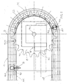
- the tool warehouse in a numerical control machining centre and the like (the latter being not illustrated here), according to an exemplifying embodiment of the present invention, is designated as a whole with 10 (figure 1).
- Said tool warehouse 10 mainly comprises:
- the change station 16 described above comprises an exchanger (the field 12.1) swivelling for an angular amplitude substantially of ⁇ 90° and with a single place. It is suitable for the so-called “random" management of the tools of the warehouse according to the invention, as it will result clearer hereinafter.
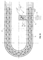
- each bush 15 has a shape substantially complementary to the cavity between two adjacent teeth of the wheel itself, so that along the whole semi-circular curve 11C occupied by said wheel 13 each bush 15, housing in a cavity between the teeth of the wheel, is dragged integrally with the same.
- each bush 15 supports a pair of rollers 15.2, opposed therebetween and assembled idle onto respective axes parallel to the one of the bush itself.
- Said rollers 15.2 partially come out from the body of the bush 15 and rest onto the opposed walls of the channel-like track 12, so as to facilitate the sliding of the bushes themselves.
- said gear wheel 13 has a recess 13.1 (figure 2) at each cavity between pairs of adjacent teeth, in order to house therein the portion of one of said rollers 15.2 coming out from the outline of the bush 15 received in said same cavity, whereas the other roller 15.2 rolls against the outer wall of the track 12.
- the linear development of the track 12 substantially corresponds to a whole multiple of the width "p" (figures 1, 3) of each bush 15 (wherein, "p" is the warehouse pitch), so that the bushes 15 are juxtaposed side by side, as said, to fill-up the track itself.
- detecting means 18 for example proximity detecting means, is provided, whereas the bush alone 15.0 is equipped with a member 18.1 apt to be detected by said detecting means 18.
- Such arrangement allows to define precisely a position "0" or a starting position of the whole set of bushes 15 slidingly housed in the track 12.
- the position of each bush 15 is always univocally determined.
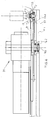
- each bush 15 by means of an outer circumferential groove 15.3 (figures 4, 5), slidingly engages the opposed free edges 11. 3 (made of antifriction material) of the channel-like guide 11, whereas it is slidingly guided against the opposed walls of the guide itself by means of the two idle rollers thereof 15.2.
- the tool-holding bushes 15 are led to move all together along said track 12.
- the simultaneous motion of all the bushes 15 is stopped, by halting the gear wheel 13, when the bush chosen for the tool change is at the station 16.
- the section 12.1 of the track 12 is rotated, for example, by 90° around the pin 12.2, by making it to overturn outwards the track 12, together with the chosen bush 15 stationing therein (figure 6).
- Such bush 15, overturned by 90° out of the track 12 is thus ready for the tool changing operation.
- said bush 15 is brought back in the track 12, by inverse overturning, by retracting the stem 16.2 of the actuator 16.1.
- the here described change station 16' comprises an exchanger (the field 12.1') swivelling for an angular amplitude substantially of ⁇ 90° and it has a single place. It is suitable for the so-called “random" management of the tools of the warehouse according to the invention, as it will result clearer hereinafter.
- Said change station 16' is provided at a rectilinear part of said track 12.
- the structure and the operation of said station are the same of the ones of the above-described station 16.
- a fixed actuator 16.1' identical to the actuator 16 for controlling the selective coming out of one of said bushes 15 at a time is arranged at said change station 16', in a more internal area with respect to the track 12.
- the axis thereof lies in a transversal vertical plane of the track 12.
- the stem 16.2' of said actuator is articulated to the free end thereof, by means of a pin 16.3', with respect to a track section 12.1' (identical to the section 12.1), assembled swivelling for an angle, for example, of ⁇ 90° with respect to the remaining portion of the track itself by means of a pin with axis parallel to the one of the pin 16. 3' (but not visible in said figure).
- the description of the station 16 and of the operation thereof is referred to.
- the here described change station 16" comprises an exchanger (the field 12.1") with linear translation, with reciprocating motion, in direction transversal to the track and with a single place. It is suitable, too, for the so-called “random" management of the tools of the warehouse according to the invention.
- Said change station 16" is provided in the centre of the curve 11C of the track 12 opposed to the one occupied by the gear wheel 13.
- a fixed actuator 16.1" for controlling the selective coming out of one of said bushes 15 at a time is provided at said change station 16".
- Said actuator 16.1" is constituted by an hydraulic or pneumatic cylinder, articulated at one end with respect to said base plate 11.1, the axis thereof is contained in the longitudinal vertical mid-plane of the track 12 and the stem thereof 16.2" is connected to the free end thereof with respect to a track section 12.1" (substantially identical to the section 12.1), assembled sliding along a pair of rectilinear prysmatic guides 16.3", parallel therebetween and with respect to said mid-plane and extended at and outside the track 12, substantially in the plane of said base plate 11.1 of the track itself.
- a bush 15 is illustrated with dots and dashes, when it is brought out of the track by the actuator 16.1" along said guides 16.3" for performing the tool changing operation.
- the here described change station 16"' comprises an exchanger (the field 12.1"') with linear translation, with reciprocating motion, in direction transversal to the track and with a single place. It is suitable, too, for the so-called “random" management of the tools of the warehouse according to the invention.
- Said change station 16"' is provided in a rectilinear part of said track 12.
- the structure and the operation of said station are the same of the ones of the above-described station 16".
- the description given above of said change station 16" is then referred to.
- the here described change station 160 comprises an exchanger (the body 120) swivelling for an angular amplitude substantially of ⁇ 90° and with a double place. It is suitable both for the so-called “random” management and for the "fixed-place" one of the tools of the warehouse according to the invention, as it will result hereinafter.
- Said change station 160 in said track 12, in the example, is provided in the centre of the curve 11C opposed to the one occupied by the gear wheel 13.
- a fixed actuator 160.1 for controlling the selective coming out of one of said bushes 15 at a time is arranged at said change station 160, in a more internal area with respect to the track 12.
- Said actuator 160.1 is constituted by an hydraulic or pneumatic cylinder, articulated at one end to said base plate 11.1, the axis thereof is contained in the longitudinal vertical mid-plane of the track 12 and the stem thereof 160.2 is articulated to the free end thereof, by means of a pin 160.3, with respect to a parallelepiped body 120, which occupies a track part 12 with a width at least corresponding to said pitch "p" and it is assembled swivelling with respect to the remaining portion of the track itself by means of a pin 120.2, so as to arrange alternatively a first or a second one of two adjacent side faces (120.10, 120. 11) at the track itself.
- Said articulation pin 160.3 of the stem 160.2 and said articulation pin 120.2 of said parallelepiped body 120 have the axes thereof mainly orthogonal with respect to said longitudinal vertical mid-plane.
- a corresponding track section is respectively formed onto said first and second faces 120.10, 120.11 of said parallelepiped body 120.
- Said track sections 120.10, 120.11, as said, have a width at least equal to the above-mentioned pitch "p" (width of a bush 15) and they correspond as to shape and arrangement to the remaining portion of the track 12.
- the second track section 120.11 receives a so-called "false bush” 150, which corresponds to a bush 15 with the difference that it does not have any axial cavity to house a tool therein.
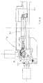
- the tool change is performed in said station 160 by making use of the first track section 120.10 with related bush 15, which is swivelled from the horizontal position (figure 12, wherein the bush axis is vertical) to the vertical position (figure 13, wherein the bush axis is horizontal) and viceversa, by means of the actuator 160.1.
- the description given by referring to figures 1 to 6 is referred to.
- the tool change is performed for example by using also the second track section 120.11 with related false bush 150, which is made to swivel from the vertical position (figure 12, wherein the axis of the false bush is horizontal) to the horizontal one (figure 13, wherein the axis of the false bush is vertical) and viceversa, by means of the actuator 160.1.
- the description given hereinafter, in particular with reference to figures 20.1 to 20.8, is referred to.
- the here illustrated change station 160' corresponds, as to structure and function, to the above-described station 160, with the only difference that it is arranged along a rectilinear part of the track 12. Therefore, the additional description is omitted.
- the here described change station 160 comprises an exchanger (the body 120") with linear translation, with reciprocating motion, in direction transversal to the track and with a double place. It is suitable both for the so-called “random” management and for the "fixed-place" one of the tools of the warehouse according to the invention, as it will result hereinafter.
- Said change station 160" is provided in the centre of the curve 11C of the track 12 opposed to the one occupied by the gear wheel 13.
- a fixed actuator 160.1" is arranged at said change station 160", which is constituted by an hydraulic or pneumatic cylinder, articulated to one end with respect to said base plate 11.1, the axis thereof is contained in the longitudinal vertical mid-plane of the track 12 and the stem thereof 160.2" is connected to the free end thereof with respect to a parallelepiped body 120", which occupied a part of the track 12 with a width at least corresponding to said pitch "p” and it is assembled sliding by translation in transversal direction with respect to the remaining portion of the track itself by means of said actuator 160.1", so as to arrange alternatively a first or a second one of two adjacent portions thereof (120.10", 120.11") at the track itself.
- Said parallelepiped body 120" is mounted sliding along a pair of rectilinear prysmatic guides 160.3", parallel therebetween and with respect to said mid-plane and extended at and inside the track 12, below said base plate 11.1 of the track itself.
- a usual tool-holding bush is designated with 15, whereas a false bush is designated with 150", as described above.
- said first and second adjacent portions 120.10", 120.11" of said parallelepiped body 120 are shaped each one like a respective track section 12.
- Said track sections 120.10", 120.11", as said, have width at least equal to the above-mentioned pitch "p" (width of a bush 15) and they correspond as to shape and arrangement to the remaining portion of the track 12, so that the track unwinds without solution of continuity also at said station 160", when one of said sections is brought in alignment with the track itself.
- the first track section 120.10 is arranged in alignment with the remaining portion of the track 12
- the second track section 120.11 is arranged in alignment with the remaining portion of the track 12.
- the here illustrated change station 160"' corresponds, as to structure and function, to the station 160" described above, with the only difference that it is arranged along a rectilinear part of the track 12. The additional description is therefore omitted.
- the parts similar to those of said station 160" are designated with the same references.
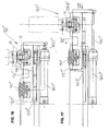
- the stem of the actuator 160.1" (figure 17) is extended, the second track section 120.11” is arranged in alignment with the remaining portion of the track 12, whereas the bush 15 with related tool is extracted linearly from the track 12 and approached to the exchanger S. Under this condition, the second track section 120.11" with the false bush 150" is aligned with respect to the track 12.
- the exchanger S performs the exchange between the tool 1, picked-up from the spindle of the machine, and the tool "6PF", inserted onto the spindle of the machine, and it places said tool 1 onto the bush 15 which is in the first track section 120.10" extended with respect to the track 12.
- an empty bush 15 (designated with five-point star) is brought to occupy the second track section 120.11", whereas the false bush 150" and the two adjacent empty bushes are correspondingly translated along said track.
- the stem of the actuator 160.1" is retracted, so that the first track section 120.10" with the bush holding the tool 1 is aligned with respect to the track 12.
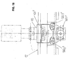
- a bush 15 bearing the tool "12" is made to move forward by a given number of places as far as occupying the first track section 120.10" of the station 160"'; then, the stem of the actuator 160.1" is extended, so as to extend beyond the track itself said first section 120.10", which thus exhibits the tool "12” to the exchanger S for the exchange, whereas the second track section 120.11" with empty bush 15" occupies the track 12.
- the exchanger S performs the exchange between the tool with large diameter "6PF” and the normalized tool "12". Such tool is inserted into the spindle of the machine, whereas the oversize tool "6PF” is inserted into the bush 15 occupying the first track section 120.10" extended beyond the track itself.
- the present invention makes possible the contemporaneous management of the tools in "random” mode, for the tools with diameter smaller than or equal to the warehouse pitch, and in "fixed-place” mode for the tools with larger dimensions, without being at disadvantage of the exchange time in any way.
- a - slide or tilter - exchanger having two perfectly identical seats (120.10. 120.11, 120.10", 120.11") and holding in the first seat the bush with the tool to be exchanged and in the second seat a false bush (150, 150") identical to the first one, but without tool, operates in the change station (160, 160', 160", 160"').
- the false bush arranges in the place of the extracted bush, allowing the motion of the warehouse in the so-called "masked" time (that is whereas the tool machine continues to work), searching for the position with fixed place wherein the bulky tool will be discharged. In this way, the false bush always guarantees the motion continuity of the tool-holding bushes 15 along the track 12.
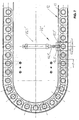
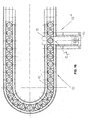
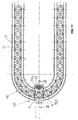
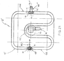
- a tool warehouse according to another embodiment of the invention is designated with 10'.
- the warehouse 10' has a closed-ring-like track 12', shaped (seen in elevation) substantially like an upside-down U and having an inner loop with a semi-circular curve 11C.
- Said warehouse 10' comprises a gear wheel 13, mainly coplanar and coaxial with respect to said semi-circular curve 11C of the track 12', so that substantially half of the toothing thereof extends in said same curve.
- Electrically-operated geared motor means 14 controls selectively the rotation of said gear wheel 13.
- a plurality of identical tool-holding bushes 15 is juxtaposed in said track 12' two by two in mutual contact and to fill-in the track 12' itself, the whole according to an arrangement similar to what described by referring to the first embodiment (only some bushes 15 are represented in figure 21, for sake of illustration clarity).
- said track 12' comprises a first outlet station 106' arranged along a rectilinear part 11R of the track itself and wherein, by means of an actuator 16.1', the selective coming out of one of said bushes 15 at a time is controlled, by means of angular rotation outwardly together with a section of the track itself (as in the station 16 of the first embodiment).
- another outlet station, designated with 106" is provided in another rectilinear part 11R of the same track 12', wherein the selective coming out of one of said bushes 15 at a time is controlled by means of linear extraction towards the outside of the track itself.
- only one of said stations can be provided in the track 12'.
- the gear wheel for dragging the tool-holding bushes is arranged at a rectilinear part of the track including the bushes themselves juxtaposed therebetween for the filling-in. Also by means of this arrangement, when said gear wheel is moved into rotation, a bush at a time is received in a corresponding cavity between adjacent teeth of the wheel itself, it remains therein while it is dragged to cover a rectilinear part of the track and it is then released downwards the wheel itself. After this, said bush is moved, together with all other bushes outside said gear wheel, along the remaining portion of said track due to the push by the other bushes which are gradually dragged by said wheel.
- the gear wheel if it is arranged in a curve of the track, can occupy a portion only of the corresponding curve in said track.
- An advantage of the tool warehouse according to the invention lies in the possibility of providing an outlet of the tool-holding bushes in any position along the track, in particular also in curve, as there are not chain dragging means.
- Another advantage lies in the sensible structural simplification of the means for dragging the tool-holding bushes along the track containing them. Furthermore, the means for dragging the tool-holding bushes is compact and allows to obtain a high constructive accuracy.
- the invention allows to achieve the objects illustrated in the premises in a simple and effective way.
Landscapes
- Engineering & Computer Science (AREA)
- Mechanical Engineering (AREA)
- Warehouses Or Storage Devices (AREA)
- Automatic Tool Replacement In Machine Tools (AREA)
- Knitting Machines (AREA)
- Numerical Control (AREA)
Applications Claiming Priority (1)
| Application Number | Priority Date | Filing Date | Title |
|---|---|---|---|
| IT000692A ITTO20060692A1 (it) | 2006-09-28 | 2006-09-28 | Magazzino utensili in un centro di lavoro a controllo numerico e simili |
Publications (3)
| Publication Number | Publication Date |
|---|---|
| EP1905535A2 true EP1905535A2 (fr) | 2008-04-02 |
| EP1905535A3 EP1905535A3 (fr) | 2008-05-14 |
| EP1905535B1 EP1905535B1 (fr) | 2009-12-30 |
Family
ID=38829173
Family Applications (1)
| Application Number | Title | Priority Date | Filing Date |
|---|---|---|---|
| EP07019017A Active EP1905535B1 (fr) | 2006-09-28 | 2007-09-27 | Magasin à outils dans un centre d'usinage à commande numérique et similaires et processus de changement d'outil dans un tel magasin |
Country Status (4)
| Country | Link |
|---|---|
| EP (1) | EP1905535B1 (fr) |
| AT (1) | ATE453484T1 (fr) |
| DE (1) | DE602007004048D1 (fr) |
| IT (1) | ITTO20060692A1 (fr) |
Cited By (10)
| Publication number | Priority date | Publication date | Assignee | Title |
|---|---|---|---|---|
| EP2565015A1 (fr) * | 2011-08-29 | 2013-03-06 | Düspohl Maschinenbau GmbH | Dispositif et procédé destinés au rééquipement de machines d'enrobage de profilés |
| CN106312308A (zh) * | 2015-06-29 | 2017-01-11 | 通快机械股份公司 | 喷嘴更换器和具有喷嘴更换器的激光加工机 |
| CN107470957A (zh) * | 2017-08-15 | 2017-12-15 | 苏州谷夫道自动化科技有限公司 | 多头加工中心及用该多头加工中心的换刀方法 |
| CN107486745A (zh) * | 2017-08-15 | 2017-12-19 | 苏州谷夫道自动化科技有限公司 | 刀库组件及加工中心 |
| CN108972098A (zh) * | 2018-08-30 | 2018-12-11 | 江西衡源智能装备有限公司 | 刀库组件及具有其的加工中心 |
| EP3446827A4 (fr) * | 2016-04-19 | 2020-03-25 | Kitamura Machinery Co., Ltd. | Système d'échange d'outil automatique pour machines-outils |
| CN112476005A (zh) * | 2020-11-19 | 2021-03-12 | 南通格美工业数控设备有限公司 | 一种五轴联动数控加工中心用可变轨刀片组 |
| CN113798894A (zh) * | 2021-11-19 | 2021-12-17 | 江苏德杰机械设备有限公司 | 一种立体式轨道输送式刀库 |
| IT202100025403A1 (it) * | 2021-10-04 | 2023-04-04 | Cft Rizzardi S R L | Magazzino portautensili per un sistema cambio utensili automatico |
| CN117300700A (zh) * | 2023-11-30 | 2023-12-29 | 综欣工业装备(潍坊)有限公司 | 一种链式刀库系统 |
Citations (1)
| Publication number | Priority date | Publication date | Assignee | Title |
|---|---|---|---|---|
| JPH06246572A (ja) | 1993-02-19 | 1994-09-06 | Howa Mach Ltd | 工作機械のツールマガジン装置 |
Family Cites Families (6)
| Publication number | Priority date | Publication date | Assignee | Title |
|---|---|---|---|---|
| US3412459A (en) * | 1964-01-10 | 1968-11-26 | Giddings & Lewis | Automatic tool changing system |
| CH521818A (de) * | 1970-04-23 | 1972-04-30 | Kearney & Trecker Corp | Werkzeugmaschine |
| GB1364645A (en) * | 1970-08-28 | 1974-08-29 | Olivetti & Co Spa | Machine tool with automatic toolchange |
| KR880000826B1 (ko) * | 1985-05-31 | 1988-05-14 | 도시바 기까이 가부시끼가이샤 | 자동공구 교환장치 |
| US6042524A (en) * | 1997-07-31 | 2000-03-28 | Brother Kogyo Kabushiki Kaisha | Tool storage device having tilting mechanism |
| DE20111119U1 (de) * | 2001-07-10 | 2001-10-11 | Demmeler, Johannes, 87737 Boos | Einrichtung zum Bevorraten und Bereitstellen von Teilen |
-
2006
- 2006-09-28 IT IT000692A patent/ITTO20060692A1/it unknown
-
2007
- 2007-09-27 DE DE602007004048T patent/DE602007004048D1/de active Active
- 2007-09-27 AT AT07019017T patent/ATE453484T1/de not_active IP Right Cessation
- 2007-09-27 EP EP07019017A patent/EP1905535B1/fr active Active
Patent Citations (1)
| Publication number | Priority date | Publication date | Assignee | Title |
|---|---|---|---|---|
| JPH06246572A (ja) | 1993-02-19 | 1994-09-06 | Howa Mach Ltd | 工作機械のツールマガジン装置 |
Cited By (15)
| Publication number | Priority date | Publication date | Assignee | Title |
|---|---|---|---|---|
| EP2565015A1 (fr) * | 2011-08-29 | 2013-03-06 | Düspohl Maschinenbau GmbH | Dispositif et procédé destinés au rééquipement de machines d'enrobage de profilés |
| CN106312308A (zh) * | 2015-06-29 | 2017-01-11 | 通快机械股份公司 | 喷嘴更换器和具有喷嘴更换器的激光加工机 |
| EP3446827A4 (fr) * | 2016-04-19 | 2020-03-25 | Kitamura Machinery Co., Ltd. | Système d'échange d'outil automatique pour machines-outils |
| US10780538B2 (en) | 2016-04-19 | 2020-09-22 | Kitamura Machinery Co., Ltd. | Automatic tool exchange system for machine tools |
| CN107486745A (zh) * | 2017-08-15 | 2017-12-19 | 苏州谷夫道自动化科技有限公司 | 刀库组件及加工中心 |
| CN107470957A (zh) * | 2017-08-15 | 2017-12-15 | 苏州谷夫道自动化科技有限公司 | 多头加工中心及用该多头加工中心的换刀方法 |
| CN108972098A (zh) * | 2018-08-30 | 2018-12-11 | 江西衡源智能装备有限公司 | 刀库组件及具有其的加工中心 |
| CN112476005A (zh) * | 2020-11-19 | 2021-03-12 | 南通格美工业数控设备有限公司 | 一种五轴联动数控加工中心用可变轨刀片组 |
| CN112476005B (zh) * | 2020-11-19 | 2022-04-29 | 南通格美工业数控设备有限公司 | 一种五轴联动数控加工中心用可变轨刀片组 |
| IT202100025403A1 (it) * | 2021-10-04 | 2023-04-04 | Cft Rizzardi S R L | Magazzino portautensili per un sistema cambio utensili automatico |
| EP4159365A1 (fr) | 2021-10-04 | 2023-04-05 | CFT Rizzardi S.r.l. | Magasin d'outils pour un changeur d'outils automatique |
| CN113798894A (zh) * | 2021-11-19 | 2021-12-17 | 江苏德杰机械设备有限公司 | 一种立体式轨道输送式刀库 |
| CN113798894B (zh) * | 2021-11-19 | 2022-03-01 | 江苏德杰机械设备有限公司 | 一种立体式轨道输送式刀库 |
| CN117300700A (zh) * | 2023-11-30 | 2023-12-29 | 综欣工业装备(潍坊)有限公司 | 一种链式刀库系统 |
| CN117300700B (zh) * | 2023-11-30 | 2024-03-08 | 综欣工业装备(潍坊)有限公司 | 一种链式刀库系统 |
Also Published As
| Publication number | Publication date |
|---|---|
| EP1905535A3 (fr) | 2008-05-14 |
| ITTO20060692A1 (it) | 2008-03-29 |
| ATE453484T1 (de) | 2010-01-15 |
| EP1905535B1 (fr) | 2009-12-30 |
| DE602007004048D1 (de) | 2010-02-11 |
Similar Documents
| Publication | Publication Date | Title |
|---|---|---|
| EP1905535B1 (fr) | Magasin à outils dans un centre d'usinage à commande numérique et similaires et processus de changement d'outil dans un tel magasin | |
| US5662014A (en) | Automatic bar stock feeding apparatus for machine tools, in particular automatic lathes | |
| US4590662A (en) | Tool changing machine of machine tool | |
| DK2726267T3 (en) | Turning device for an injection molding device | |
| US3509619A (en) | Multi-head drilling machine with head changing means | |
| ITTO20090538A1 (it) | Tornio a controllo numerico con dispositivo di carico/scarico automatico dei pezzi e con dispositivo di cambio utensile automatico | |
| US3760491A (en) | Tool change mechanism | |
| US6394941B2 (en) | Press with automatic tool changing function and tool cartridge changing device | |
| CN214392428U (zh) | 一种可检测汽车轴承套圈内壁平整度套圈加工装置 | |
| US8821083B2 (en) | Machine tool including a plurality of tool spindles and a frame shaped rack | |
| FR2480659A1 (fr) | Centre d'usinage a changeur d'outil a broche basculante | |
| US5624365A (en) | Machine tool | |
| IT8922392A1 (it) | Impianto di lavorazione di pezzi su pallet mediante macchina utensile con un unico dispositivo per il trasferimento dei pallet tra una stazione di lavoro e un'adiacente stazione di carico/scarico dei pallet. | |
| KR0181765B1 (ko) | 공작 기계용 공구 메거진 | |
| JPS5939256B2 (ja) | 自動工具交換装置 | |
| EP4159365B1 (fr) | Magasin d'outils pour un changeur d'outils automatique | |
| DE102005003220B4 (de) | Werkzeugwechseleinrichtung und -verfahren | |
| ITMI991905A1 (it) | Unita' operatrice con cambio utensile automatico per macchina transfer e macchina transfer provvista di tale unita' operatrice | |
| US4497410A (en) | Automatic tool changer for a lathe | |
| US5946885A (en) | Cigarette packaging machine including a rotary folding turret having two releasably interconnected turret portions | |
| JP2002520171A (ja) | マシニングセンター用の工具交換装置 | |
| CN116803603A (zh) | 刀库装置 | |
| US8087332B2 (en) | Lathe | |
| US7243583B2 (en) | Lathe, in particular multi-spindle automatic lathe | |
| CZ292525B6 (cs) | Zařízení na výměnu nástrojů ve vřetenu obráběcího stroje |
Legal Events
| Date | Code | Title | Description |
|---|---|---|---|
| PUAI | Public reference made under article 153(3) epc to a published international application that has entered the european phase |
Free format text: ORIGINAL CODE: 0009012 |
|
| AK | Designated contracting states |
Kind code of ref document: A2 Designated state(s): AT BE BG CH CY CZ DE DK EE ES FI FR GB GR HU IE IS IT LI LT LU LV MC MT NL PL PT RO SE SI SK TR |
|
| AX | Request for extension of the european patent |
Extension state: AL BA HR MK YU |
|
| PUAL | Search report despatched |
Free format text: ORIGINAL CODE: 0009013 |
|
| AK | Designated contracting states |
Kind code of ref document: A3 Designated state(s): AT BE BG CH CY CZ DE DK EE ES FI FR GB GR HU IE IS IT LI LT LU LV MC MT NL PL PT RO SE SI SK TR |
|
| AX | Request for extension of the european patent |
Extension state: AL BA HR MK RS |
|
| 17P | Request for examination filed |
Effective date: 20081104 |
|
| 17Q | First examination report despatched |
Effective date: 20081209 |
|
| AKX | Designation fees paid |
Designated state(s): AT BE BG CH CY CZ DE DK EE ES FI FR GB GR HU IE IS IT LI LT LU LV MC MT NL PL PT RO SE SI SK TR |
|
| RAP1 | Party data changed (applicant data changed or rights of an application transferred) |
Owner name: COLOMBO FILIPPETTI TORINO S.R.L. |
|
| GRAP | Despatch of communication of intention to grant a patent |
Free format text: ORIGINAL CODE: EPIDOSNIGR1 |
|
| GRAS | Grant fee paid |
Free format text: ORIGINAL CODE: EPIDOSNIGR3 |
|
| GRAA | (expected) grant |
Free format text: ORIGINAL CODE: 0009210 |
|
| AK | Designated contracting states |
Kind code of ref document: B1 Designated state(s): AT BE BG CH CY CZ DE DK EE ES FI FR GB GR HU IE IS IT LI LT LU LV MC MT NL PL PT RO SE SI SK TR |
|
| REG | Reference to a national code |
Ref country code: GB Ref legal event code: FG4D |
|
| REG | Reference to a national code |
Ref country code: CH Ref legal event code: EP |
|
| REG | Reference to a national code |
Ref country code: IE Ref legal event code: FG4D |
|
| REF | Corresponds to: |
Ref document number: 602007004048 Country of ref document: DE Date of ref document: 20100211 Kind code of ref document: P |
|
| PG25 | Lapsed in a contracting state [announced via postgrant information from national office to epo] |
Ref country code: SE Free format text: LAPSE BECAUSE OF FAILURE TO SUBMIT A TRANSLATION OF THE DESCRIPTION OR TO PAY THE FEE WITHIN THE PRESCRIBED TIME-LIMIT Effective date: 20091230 Ref country code: LT Free format text: LAPSE BECAUSE OF FAILURE TO SUBMIT A TRANSLATION OF THE DESCRIPTION OR TO PAY THE FEE WITHIN THE PRESCRIBED TIME-LIMIT Effective date: 20091230 Ref country code: FI Free format text: LAPSE BECAUSE OF FAILURE TO SUBMIT A TRANSLATION OF THE DESCRIPTION OR TO PAY THE FEE WITHIN THE PRESCRIBED TIME-LIMIT Effective date: 20091230 |
|
| REG | Reference to a national code |
Ref country code: NL Ref legal event code: VDEP Effective date: 20091230 |
|
| LTIE | Lt: invalidation of european patent or patent extension |
Effective date: 20091230 |
|
| PG25 | Lapsed in a contracting state [announced via postgrant information from national office to epo] |
Ref country code: PL Free format text: LAPSE BECAUSE OF FAILURE TO SUBMIT A TRANSLATION OF THE DESCRIPTION OR TO PAY THE FEE WITHIN THE PRESCRIBED TIME-LIMIT Effective date: 20091230 Ref country code: SI Free format text: LAPSE BECAUSE OF FAILURE TO SUBMIT A TRANSLATION OF THE DESCRIPTION OR TO PAY THE FEE WITHIN THE PRESCRIBED TIME-LIMIT Effective date: 20091230 Ref country code: LV Free format text: LAPSE BECAUSE OF FAILURE TO SUBMIT A TRANSLATION OF THE DESCRIPTION OR TO PAY THE FEE WITHIN THE PRESCRIBED TIME-LIMIT Effective date: 20091230 |
|
| PG25 | Lapsed in a contracting state [announced via postgrant information from national office to epo] |
Ref country code: AT Free format text: LAPSE BECAUSE OF FAILURE TO SUBMIT A TRANSLATION OF THE DESCRIPTION OR TO PAY THE FEE WITHIN THE PRESCRIBED TIME-LIMIT Effective date: 20091230 |
|
| PG25 | Lapsed in a contracting state [announced via postgrant information from national office to epo] |
Ref country code: PT Free format text: LAPSE BECAUSE OF FAILURE TO SUBMIT A TRANSLATION OF THE DESCRIPTION OR TO PAY THE FEE WITHIN THE PRESCRIBED TIME-LIMIT Effective date: 20100430 Ref country code: ES Free format text: LAPSE BECAUSE OF FAILURE TO SUBMIT A TRANSLATION OF THE DESCRIPTION OR TO PAY THE FEE WITHIN THE PRESCRIBED TIME-LIMIT Effective date: 20100410 Ref country code: NL Free format text: LAPSE BECAUSE OF FAILURE TO SUBMIT A TRANSLATION OF THE DESCRIPTION OR TO PAY THE FEE WITHIN THE PRESCRIBED TIME-LIMIT Effective date: 20091230 Ref country code: RO Free format text: LAPSE BECAUSE OF FAILURE TO SUBMIT A TRANSLATION OF THE DESCRIPTION OR TO PAY THE FEE WITHIN THE PRESCRIBED TIME-LIMIT Effective date: 20091230 Ref country code: IS Free format text: LAPSE BECAUSE OF FAILURE TO SUBMIT A TRANSLATION OF THE DESCRIPTION OR TO PAY THE FEE WITHIN THE PRESCRIBED TIME-LIMIT Effective date: 20100430 Ref country code: BG Free format text: LAPSE BECAUSE OF FAILURE TO SUBMIT A TRANSLATION OF THE DESCRIPTION OR TO PAY THE FEE WITHIN THE PRESCRIBED TIME-LIMIT Effective date: 20100330 Ref country code: EE Free format text: LAPSE BECAUSE OF FAILURE TO SUBMIT A TRANSLATION OF THE DESCRIPTION OR TO PAY THE FEE WITHIN THE PRESCRIBED TIME-LIMIT Effective date: 20091230 |
|
| PG25 | Lapsed in a contracting state [announced via postgrant information from national office to epo] |
Ref country code: BE Free format text: LAPSE BECAUSE OF FAILURE TO SUBMIT A TRANSLATION OF THE DESCRIPTION OR TO PAY THE FEE WITHIN THE PRESCRIBED TIME-LIMIT Effective date: 20091230 Ref country code: CZ Free format text: LAPSE BECAUSE OF FAILURE TO SUBMIT A TRANSLATION OF THE DESCRIPTION OR TO PAY THE FEE WITHIN THE PRESCRIBED TIME-LIMIT Effective date: 20091230 Ref country code: SK Free format text: LAPSE BECAUSE OF FAILURE TO SUBMIT A TRANSLATION OF THE DESCRIPTION OR TO PAY THE FEE WITHIN THE PRESCRIBED TIME-LIMIT Effective date: 20091230 |
|
| PG25 | Lapsed in a contracting state [announced via postgrant information from national office to epo] |
Ref country code: GR Free format text: LAPSE BECAUSE OF FAILURE TO SUBMIT A TRANSLATION OF THE DESCRIPTION OR TO PAY THE FEE WITHIN THE PRESCRIBED TIME-LIMIT Effective date: 20100331 Ref country code: CY Free format text: LAPSE BECAUSE OF FAILURE TO SUBMIT A TRANSLATION OF THE DESCRIPTION OR TO PAY THE FEE WITHIN THE PRESCRIBED TIME-LIMIT Effective date: 20091230 |
|
| PLBE | No opposition filed within time limit |
Free format text: ORIGINAL CODE: 0009261 |
|
| STAA | Information on the status of an ep patent application or granted ep patent |
Free format text: STATUS: NO OPPOSITION FILED WITHIN TIME LIMIT |
|
| 26N | No opposition filed |
Effective date: 20101001 |
|
| PG25 | Lapsed in a contracting state [announced via postgrant information from national office to epo] |
Ref country code: DK Free format text: LAPSE BECAUSE OF FAILURE TO SUBMIT A TRANSLATION OF THE DESCRIPTION OR TO PAY THE FEE WITHIN THE PRESCRIBED TIME-LIMIT Effective date: 20091230 |
|
| PG25 | Lapsed in a contracting state [announced via postgrant information from national office to epo] |
Ref country code: IT Free format text: LAPSE BECAUSE OF FAILURE TO SUBMIT A TRANSLATION OF THE DESCRIPTION OR TO PAY THE FEE WITHIN THE PRESCRIBED TIME-LIMIT Effective date: 20091230 |
|
| PG25 | Lapsed in a contracting state [announced via postgrant information from national office to epo] |
Ref country code: MC Free format text: LAPSE BECAUSE OF NON-PAYMENT OF DUE FEES Effective date: 20100930 |
|
| REG | Reference to a national code |
Ref country code: FR Ref legal event code: ST Effective date: 20110531 |
|
| PG25 | Lapsed in a contracting state [announced via postgrant information from national office to epo] |
Ref country code: IE Free format text: LAPSE BECAUSE OF NON-PAYMENT OF DUE FEES Effective date: 20100927 Ref country code: FR Free format text: LAPSE BECAUSE OF NON-PAYMENT OF DUE FEES Effective date: 20100930 |
|
| PG25 | Lapsed in a contracting state [announced via postgrant information from national office to epo] |
Ref country code: MT Free format text: LAPSE BECAUSE OF FAILURE TO SUBMIT A TRANSLATION OF THE DESCRIPTION OR TO PAY THE FEE WITHIN THE PRESCRIBED TIME-LIMIT Effective date: 20091230 |
|
| REG | Reference to a national code |
Ref country code: CH Ref legal event code: PL |
|
| GBPC | Gb: european patent ceased through non-payment of renewal fee |
Effective date: 20110927 |
|
| PG25 | Lapsed in a contracting state [announced via postgrant information from national office to epo] |
Ref country code: LI Free format text: LAPSE BECAUSE OF NON-PAYMENT OF DUE FEES Effective date: 20110930 Ref country code: CH Free format text: LAPSE BECAUSE OF NON-PAYMENT OF DUE FEES Effective date: 20110930 |
|
| PG25 | Lapsed in a contracting state [announced via postgrant information from national office to epo] |
Ref country code: GB Free format text: LAPSE BECAUSE OF NON-PAYMENT OF DUE FEES Effective date: 20110927 |
|
| PG25 | Lapsed in a contracting state [announced via postgrant information from national office to epo] |
Ref country code: HU Free format text: LAPSE BECAUSE OF FAILURE TO SUBMIT A TRANSLATION OF THE DESCRIPTION OR TO PAY THE FEE WITHIN THE PRESCRIBED TIME-LIMIT Effective date: 20100701 Ref country code: LU Free format text: LAPSE BECAUSE OF NON-PAYMENT OF DUE FEES Effective date: 20100927 |
|
| PG25 | Lapsed in a contracting state [announced via postgrant information from national office to epo] |
Ref country code: TR Free format text: LAPSE BECAUSE OF FAILURE TO SUBMIT A TRANSLATION OF THE DESCRIPTION OR TO PAY THE FEE WITHIN THE PRESCRIBED TIME-LIMIT Effective date: 20091230 |
|
| PGFP | Annual fee paid to national office [announced via postgrant information from national office to epo] |
Ref country code: DE Payment date: 20251022 Year of fee payment: 19 |