EP1905562A2 - Procédé et installation pour fabriquer des carreaux en céramique - Google Patents
Procédé et installation pour fabriquer des carreaux en céramique Download PDFInfo
- Publication number
- EP1905562A2 EP1905562A2 EP20070113814 EP07113814A EP1905562A2 EP 1905562 A2 EP1905562 A2 EP 1905562A2 EP 20070113814 EP20070113814 EP 20070113814 EP 07113814 A EP07113814 A EP 07113814A EP 1905562 A2 EP1905562 A2 EP 1905562A2
- Authority
- EP
- European Patent Office
- Prior art keywords
- ceramic material
- grid
- shaped body
- plant
- powder
- Prior art date
- Legal status (The legal status is an assumption and is not a legal conclusion. Google has not performed a legal analysis and makes no representation as to the accuracy of the status listed.)
- Withdrawn
Links
- 239000000919 ceramic Substances 0.000 title claims abstract description 31
- 238000000034 method Methods 0.000 title claims abstract description 24
- 238000004519 manufacturing process Methods 0.000 title claims abstract description 8
- 239000000843 powder Substances 0.000 claims abstract description 107
- 229910010293 ceramic material Inorganic materials 0.000 claims abstract description 104
- 238000000151 deposition Methods 0.000 claims abstract description 29
- 230000000284 resting effect Effects 0.000 claims abstract description 6
- 239000000463 material Substances 0.000 claims description 27
- 230000033001 locomotion Effects 0.000 claims description 12
- 238000004891 communication Methods 0.000 claims description 10
- 238000012546 transfer Methods 0.000 claims description 9
- 238000005192 partition Methods 0.000 claims description 8
- 230000003213 activating effect Effects 0.000 claims description 7
- 239000011796 hollow space material Substances 0.000 claims description 6
- 238000012358 sourcing Methods 0.000 claims description 5
- 239000000725 suspension Substances 0.000 claims description 5
- 238000013519 translation Methods 0.000 claims description 3
- 230000001747 exhibiting effect Effects 0.000 claims description 2
- 239000011159 matrix material Substances 0.000 description 12
- 238000005034 decoration Methods 0.000 description 8
- 238000013461 design Methods 0.000 description 5
- 239000011148 porous material Substances 0.000 description 4
- 238000003825 pressing Methods 0.000 description 4
- 239000000945 filler Substances 0.000 description 3
- 229910000831 Steel Inorganic materials 0.000 description 2
- 239000003086 colorant Substances 0.000 description 2
- 239000000549 coloured material Substances 0.000 description 2
- 238000009826 distribution Methods 0.000 description 2
- 238000001035 drying Methods 0.000 description 2
- 238000010304 firing Methods 0.000 description 2
- 238000002156 mixing Methods 0.000 description 2
- 239000010959 steel Substances 0.000 description 2
- 230000035508 accumulation Effects 0.000 description 1
- 238000009825 accumulation Methods 0.000 description 1
- 230000015572 biosynthetic process Effects 0.000 description 1
- 230000006835 compression Effects 0.000 description 1
- 238000007906 compression Methods 0.000 description 1
- 238000011161 development Methods 0.000 description 1
- 230000000694 effects Effects 0.000 description 1
- 239000012467 final product Substances 0.000 description 1
- 238000001033 granulometry Methods 0.000 description 1
- 230000005484 gravity Effects 0.000 description 1
- 230000002452 interceptive effect Effects 0.000 description 1
- 230000010355 oscillation Effects 0.000 description 1
- 239000000047 product Substances 0.000 description 1
- 230000000630 rising effect Effects 0.000 description 1
- 238000007493 shaping process Methods 0.000 description 1
- 238000007873 sieving Methods 0.000 description 1
- 239000004575 stone Substances 0.000 description 1
- 238000011144 upstream manufacturing Methods 0.000 description 1
- 210000003462 vein Anatomy 0.000 description 1
Images






Classifications
-
- B—PERFORMING OPERATIONS; TRANSPORTING
- B28—WORKING CEMENT, CLAY, OR STONE
- B28B—SHAPING CLAY OR OTHER CERAMIC COMPOSITIONS; SHAPING SLAG; SHAPING MIXTURES CONTAINING CEMENTITIOUS MATERIAL, e.g. PLASTER
- B28B5/00—Producing shaped articles from the material in moulds or on moulding surfaces, carried or formed by, in or on conveyors irrespective of the manner of shaping
- B28B5/02—Producing shaped articles from the material in moulds or on moulding surfaces, carried or formed by, in or on conveyors irrespective of the manner of shaping on conveyors of the endless-belt or chain type
- B28B5/021—Producing shaped articles from the material in moulds or on moulding surfaces, carried or formed by, in or on conveyors irrespective of the manner of shaping on conveyors of the endless-belt or chain type the shaped articles being of definite length
- B28B5/022—Producing shaped articles from the material in moulds or on moulding surfaces, carried or formed by, in or on conveyors irrespective of the manner of shaping on conveyors of the endless-belt or chain type the shaped articles being of definite length the moulds or the moulding surfaces being individual independant units and being discontinuously fed
-
- B—PERFORMING OPERATIONS; TRANSPORTING
- B28—WORKING CEMENT, CLAY, OR STONE
- B28B—SHAPING CLAY OR OTHER CERAMIC COMPOSITIONS; SHAPING SLAG; SHAPING MIXTURES CONTAINING CEMENTITIOUS MATERIAL, e.g. PLASTER
- B28B13/00—Feeding the unshaped material to moulds or apparatus for producing shaped articles; Discharging shaped articles from such moulds or apparatus
- B28B13/02—Feeding the unshaped material to moulds or apparatus for producing shaped articles
- B28B13/0215—Feeding the moulding material in measured quantities from a container or silo
- B28B13/022—Feeding several successive layers, optionally of different materials
-
- B—PERFORMING OPERATIONS; TRANSPORTING
- B28—WORKING CEMENT, CLAY, OR STONE
- B28B—SHAPING CLAY OR OTHER CERAMIC COMPOSITIONS; SHAPING SLAG; SHAPING MIXTURES CONTAINING CEMENTITIOUS MATERIAL, e.g. PLASTER
- B28B13/00—Feeding the unshaped material to moulds or apparatus for producing shaped articles; Discharging shaped articles from such moulds or apparatus
- B28B13/02—Feeding the unshaped material to moulds or apparatus for producing shaped articles
- B28B13/0295—Treating the surface of the fed layer, e.g. removing material or equalization of the surface
-
- B—PERFORMING OPERATIONS; TRANSPORTING
- B28—WORKING CEMENT, CLAY, OR STONE
- B28B—SHAPING CLAY OR OTHER CERAMIC COMPOSITIONS; SHAPING SLAG; SHAPING MIXTURES CONTAINING CEMENTITIOUS MATERIAL, e.g. PLASTER
- B28B15/00—General arrangement or layout of plant ; Industrial outlines or plant installations
-
- B—PERFORMING OPERATIONS; TRANSPORTING
- B28—WORKING CEMENT, CLAY, OR STONE
- B28B—SHAPING CLAY OR OTHER CERAMIC COMPOSITIONS; SHAPING SLAG; SHAPING MIXTURES CONTAINING CEMENTITIOUS MATERIAL, e.g. PLASTER
- B28B3/00—Producing shaped articles from the material by using presses; Presses specially adapted therefor
Definitions
- the invention relates in general to a method and plant for manufacturing ceramic tiles.
- ceramic tiles are manufactured starting from an unfired tile made of powdered ceramic material, which is subjected to successive stages of drying and firing up until the final product is obtained.
- the present invention relates in particular to the realisation of the unfired tile.
- the unfired tile is realised by pressing powder ceramic material internally of the forming cavity of a ceramic die.
- the ceramic die comprises a bottom die which is slidably inserted internally of a lateral matrix which defines the forming cavity, and an overlying upper die which moves vertically with respect to the bottom die in order to effect the pressing.
- the powder ceramic material is supplied to the forming cavity by a special filler box, which translates on a sliding plane located close to the die matrix.
- the translation of the filler box goes from a retracted position, in which it is positioned below a supply hopper of powder material, and an advanced position in which it lies above the bottom die of the ceramic die and releases the powder material into the forming cavity.
- a drawback of this system consists in the fact that the numerous movements of the filler box create long dead times during the ceramic die operation which, inevitably, limit the productivity of the whole system.
- These plants generally comprise a horizontal conveyor line which advances a sequence of rest platforms through a series of work stations.
- the work stations comprise one or more supply stations, a compacting station and a transfer station.
- the supply stations release a plurality of overlying layers of powder ceramic material on each platform, forming a soft slab.
- the compacting station compacts the soft slab so as to eliminate the air contained therein and obtain a pre-compacted slab.
- the transfer station then transfers the pre-compacted slab internally of the forming chamber of the ceramic die.
- the layer of the soft slab which is destined to remain in sight in the finished tiles is generally obtained using coloured ceramic powders which are distributed according to a predetermined design.
- the supply station for realising the above-mentioned layer is often provided with special dispensing heads, which move above the rest element such as to reproduce the desired designs.
- a characteristic of these heads is that they realise designs generally having poorly-defined and hazy edges which are suitable, for example, for reproducing the veins which are typical of natural stone, but are not suitable for obtaining the sharp figures typical of geometrical decorations.
- the heads do not enable a satisfactory production of the design known as mosaic, i.e. the decorations formed by a group of adjacent zones having different colours and well-delimited edges.
- An aim of the present invention is to obviate the above-described drawback by offering a simple, rational and inexpensive solution.
- the above-mentioned layer is formed in plan view by a plurality of adjacent zones of ceramic powders, which reproduce the shape of the cells of the separating grid and are separated by neat and precise edge lines.
- a variegated layer is left on the rest surface which can realise any geometric decoration, and in particular, but not only, any mosaic decoration.
- each of the cells of the shaped body can be filled with ceramic material of a different colour to the powder in the adjacent cells, or one or more adjacent cells can be filled with material of the same colour, according to the geometrical design that is to be realised.
- the method of the invention further enables realisation of both ceramic tiles decorated throughout and tiles decorated only on the surface which will be visible when laid.
- the variegated layer deposited by means of the shaped body constitutes the entire thickness of the soft slab destined to realise the tiles.
- the variegated layer realises only the surface destined to remain in view of the tile, and the thickness of the soft slab is therefore completed with at least a second layer of ceramic material generally having less aesthetically appealing characteristics.
- the second layer can be deposited directly over the variegated layer; or it can be made first, such as to define the rest surface upon which the variegated layer will subsequently be laid.
- the above-described method can be carried out using a plant comprising:
- the invention makes available a device for depositing powder ceramic material on a horizontally translating rest surface.
- the device comprises a shaped body provided with separating elements which define a plurality of cells, means for moving for moving the shaped body in a vertical direction, and means for loading for releasing a powder ceramic material internally of the cells of the grid-shaped body.
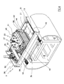
- the plant 1 for manufacturing ceramic tiles illustrated in the figures comprises a conveyor 2 which horizontally advances a sequence of platforms 10 through a series of work stations, stopping it at each of them.
- the conveyor 2 is constituted by a conveyor belt, although it might be substituted by any other suitable conveying system having the same functional characteristics.
- the work stations comprise two supply stations, respectively a decorating station 3 and a finishing station 4, which are overall aimed at realising a soft slab of ceramic powder on each platform 10.
- the decorating station 3 deposits the layer of powder material on the station which powder material is destined to remain in sight in the finished tile.
- the second station deposits a second layer of powder ceramic material above the one deposited by the decoration station 3, such as to complete the width of the soft slab.
- a compacting station 5 Downstream of the finishing station 4 is a compacting station 5, which is provided with a press 9 for compacting the soft slab in order to remove the air contained therein and to obtain a transportable compacted slab.
- a transfer station 6 in which means of known type are installed for transferring each compacted slab towards the cavity of a ceramic die 7, where it is subjected to the real pressing operation before being sent on to the drying and final firing stages.
- each platform 10 comprises a broadened base 11 at the centre of which a punch 12 is fixed, an upper face of which defines a horizontal rest surface 13 for the powder ceramic material.
- the punch 12 has a rectangular plan, but it could also be square or any other shape.
- the punch 12 is snugly inserted in a relative containing matrix 14, which is vertically mobile with respect to the underlying broadened base 11.
- the containing matrix 14 is provided with a series of vertical stems 15 projecting from the lower surface thereof, each of which stems 15 is contained in a respective hollow cylinder 16 fixed to the broadened base 11.
- the vertical stems 15 project below the broadened base 11 without interfering with the conveyor belt 2.
- Commanded means for retaining are interposed between each vertical stem 15 and the relative cylinder 16, which generate sufficient friction to prevent any undesired vertical movement of the containing matrix with respect to the punch 11.
- the vertical motions of the containing matrix 14 are caused by special raising devices 8, comprising for example a series of jacks, which are positioned below the conveyor belt 2 and act on projecting tracts of the vertical stems 15 (see figure 1).
- the raising devices 8 are located at both supply stations 3, 4 of the powder ceramic material.
- the decorating station 3 is provided with a special device for depositing the powder ceramic material, denoted in its entirety by 20.
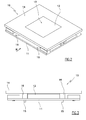
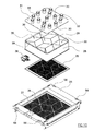
- the depositing device 20 comprises a grid-shaped body 21 which is positioned horizontally and located higher than the underlying rest surface 13 of the platform 10.
- the grid-shaped body 21 (see figure 8) comprises a grid of vertically-developing separating walls 23, which define a substantially rectangular perimeter frame 22 an internal space of which is sub-divided into a plurality of separate cells 24.
- the frame 22 exhibits, in plan view, a lateral perimeter having a same shape and substantially same dimensions as the plan-view perimeter of the punch 12 of the platform 10, such as to be snugly insertable inside the matrices 14.
- the lower edges of the separator walls 23 are all positioned at a same height, such as to contemporaneously rest on the rest surface 13.
- transversal section of the separating walls 23 exhibits a tapered lower end, such that the thickness at the lower edge is minimal, preferably around a few tenths of millimetres (see figure 9).
- the grid-shaped body 21 is fixed to a support frame 21' by which it is connected to a rigid support frame 25.
- the rigid support frame 25 is associated to means 26 for moving the shaped body 21 in a vertical direction with respect to the underlying rest surface 13.
- Means for loading are located on the support frame 25, which means for loading release a powder ceramic material into each cell 24 of the grid-shaped body 21.
- the means for loading 27 can release a different-coloured ceramic material into each cell 24, or can release ceramic material of the same colour into one or more adjacent cells 24, according to the decoration that is to be realised.
- the means for loading 27 comprise a hopper 28 for the powder ceramic material, which exhibits a profile in plan view that coincides with the plan-view profile of the perimeter frame 22 of the grid-shaped body 21 and which is located vertically above the grid-shaped body 21 itself.
- the internal volume of the hopper 28 is subdivided by a grid of separating walls 29 of a same height which define a plurality of distinct vertically-developing container cells 30, each of which contains a powder ceramic material.
- the separating walls 29 of the hopper 28 are arranged, in plan view, to form a grid having a same shape and dimensions as the grid of separating walls 23 of the grid-shaped body 21.
- the hopper 28 is superiorly closed by a cover 31 exhibiting a series of inlet holes 32, each of which opens internally of a respective container cell 30.
- Sleeves 33 are associated to the inlet holes 32, which sleeves 33, via a series of flexible spiral tubes (not illustrated), are connected to a central supply system of the powder ceramic material.
- each container cell 30 is superposed on a respective cell 24 of the grid-shaped body 21, and is open to enable outlet and direct transfer of the ceramic material internally of the cell 24.
- the hopper 28 is associated to means for selectively opening and closing the bottom of the container cells 30 of the powder ceramic material.
- the means comprise a first perforated slab 35 which closes the bottom of the hopper 28 such as to intercept all of the container cells 30, and an underlying second perforated slab 36 facing and in contact with the first perforated slab 35.
- the first and second perforated slabs 35, 36 are reciprocally slidable between an open configuration, in which they make available a plurality of passages for the powder ceramic material, and a closed position, in which they completely close the passages.
- the second perforated slab 36 is solidly fixed to the support frame 25, while the first perforated slab 35 is fixed to the hopper 28 which is mounted on the support frame 25 by means of two sliding guides 37 which enable it to move in horizontal directions.
- the movements are commanded by special actuator means 38 which move the hopper 28 alternatingly in a short run between the open and closed positions.
- the actuator means 38 comprise a pneumatic jack installed on the support frame 25, such as to act on a lateral flank of the hopper 28.
- the means for loading 27 further comprise a vibrating frame 39, located below the perforated slabs 35, 36, which vibrating frame 39 is connected to the support frame 25 by means of elastic suspension means, for example strips of soft and amorphous rubber.
- the vibrating frame 39 is substantially frame-shaped, and exhibits a shape in plan view that coincides with the plan-view shape of the frame 22 of the grid-shaped body 21, and is vertically superposed thereon.
- the vibrating frame 39 frames a sieve 40 which is therefore interposed between the outlet bottom of the container cells 30 of the powder ceramic material and the cells 24 of the grid-shaped body 21.
- the internal space of the vibrating frame 39 is subdivided by a grid of separating walls 41 into a plurality of separate areas 42, each of which communicates with a respective cell 24 of the grid-shaped body 21 and is closed by the sieve 40.
- the separating walls 41 are arranged in plan view to form a grid having the same shape and dimensions as the grid of separating walls 23 of the grid-shaped body 21, and have a vertical development which is greater than the thickness of the sieve 40, which is in an intermediate position with respect to the height thereof.
- the vibrating frame 39 is vibrated by a usual pair of vibrators 43 which generate a vertical oscillation of the frame 39 on the support frame 25.
- the vibrators 43 are electromechanical with counter-rotating cams, with a vertical and/or horizontal resultant of the centrifugal force.
- the vibration induced by the vibrators can be adjusted by acting on the angular position of the eccentric masses with respect to the rotating shaft, or by varying the rotation velocity of the motor.
- the vibrators 43 can be of the electromagnetic type with the casing fixed to the support frame 25 and the vibrating part fixed to the vibrating frame 39.
- the vibration induced by the electromagnetic vibrators can be adjusted by varying the distance between the casing and the vibrating part, or by varying the current intensity of the coil using appropriate potentiometer systems.
- the means for loading 27 comprise a vertically-developing distancing tunnel 44, having an upper end which is fixed to the support frame 25 and a lower end which is fixed to the support frame 21' of the grid-shaped body 21.
- the distancing tunnel 44 comprises an external casing 45 which exhibits a profile in plan view which coincides with the plan-view profile of the frame 21' to which it is fixed.
- the internal volume of the casing 45 is subdivided by a grid of vertical partition walls 46 of a same height which define a plurality of distinct vertically-developing drop chutes 47, each of which sets the outlet of a respective container cell 30 in communication with a respect cell 24 of the grid-shaped body 21 such as to guide the relative powder ceramic material in descent.
- partition walls 46 of the external casing 45 are arranged in plan view to form a grid having the same shape and dimensions as the grid of separating walls 23 of the grid-shaped body 21.
- the distancing tunnel 44 is transversally sub-divided into a plurality of identical superposed modular segments 48, which can be mounted and dismounted to vary the overall height of the distancing tunnel 44.
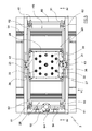
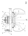
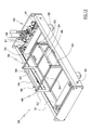
- the means 26 for moving the depositing device 20 comprise a translating group 49 on which the support frame 25 of the grid-shaped body 21 is mounted, and means for activating 50 for vertically moving the translating group 49.
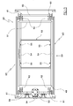
- the translating group 49 comprises a flat rectangular frame 51, internally of which a support scaffold 52 is fixed, for the support frame 25 of the grid-shaped body 21.
- the support scaffold 52 comprises four vertical columns 53 arranged substantially at the corners of the rectangle, which four columns 53 are inferiorly fixed to the flat frame 51 and are reciprocally joined at the top thereof by four horizontal beams 54.
- the support frame 25 rests on two opposite horizontal beams 54, each of which is provided with two upwardly-projecting vertical pins 55 which slidably insert in a respective through-hole 56 in the support frame 25 (see also figure 11).
- the vertical pins 55 project above the support frame 25, where they exhibit a broadened head 57 which compresses a respective elastic suspension, in the present embodiment a spring, against the upper surface of the support frame 25 (see figures 15 and 16).
- the slidable connection between the pins 55 and the holes 56 enables the support frame 25 to perform small movements in a vertical direction with respect to the support scaffold 52.
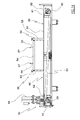
- the means for activating 50 which vertically move the translating group 49 comprise a first and a second rotating shaft, respectively 59 and 60, which are arranged parallel along two opposite sides of the flat rectangular frame 51.
- cams 61 Two identical pairs of cams 61 are keyed on the rotating shafts 59, 60, each of which cams 61 acts against a relative cam follower 62 which projects from the side of the flat frame 51 adjacent thereto.
- the cams 61 keyed on a same rotating shaft 59 are perfectly in phase with one another and are specularly arranged with respect to the cams 61 keyed on the opposite shaft 60.
- the first and the second rotating shafts 59, 60 are mechanically connected by two identical articulated systems 63.
- the articulated systems 63 are configured such as to engage the rotating shafts 59, 60 to rotate in opposite directions at equal angles.
- Both the rotating shafts 59, 60 are activated by a same motor 64, which is keyed at an intermediate point of the first rotating shaft 59.
- the platform 10 reaches the decorating station 3 with the container matrix 14 located proximal to the rest surface 13 of the punch 12, and stops exactly below the grid-shaped body 21.
- the means for moving 26 the depositing device 20 lower the grid-shaped body 21 onto the rest surface 13, locating it internally of the container matrix 14.
- the grid-shaped body 21 is lowered up until it completely rests on the rest surface 13, compensating for any small planarity irregularities thereof and enabling the device 20 to adapt to any height of the punch 11.
- the grid-shaped body 21 sub-divides the rest surface 13 into a plurality of distinct and separate zones, which are delimited by the vertically-developing separating walls 23 and by the perimeter frame 22.
- Each container cell 30 of the hopper 28 is filled with a powder ceramic material having a different colour to the colour in the adjacent container cells 30.
- the hopper 28 is shifted into the open position, so that the perforated slabs 35, 36 which intercept the outlets of the container cells 38 define a series of passages from which the powder ceramic material falls by force of gravity in a downwards direction.
- each container cell 30 passes onto the sieve 40, remaining separate from the other materials thanks to the separating walls 41 of the vibrating frame 39.
- the vibrating frame 39 is vibrated by the vibrators 43 so that the sieve 40 uniformly distributes the material over the whole of the relative area 22 and generates a plurality of substantially vertical lines of material which fall down onto the underlying rest surface 13 through the distancing tunnel 44.
- the function of the distancing tunnel 44 is to impart on the powder ceramic material a kinetic energy which is sufficient so that following the impact on the rest surface 13 it spreads over the whole area defined by the relative cell 24 of the grid-shaped body 21.
- the height of the distancing tunnel 44 therefore depends substantially on the type of powder material used and can be varied by selecting the number of modular segments 48 it is made up of.
- the powder ceramic material When the powder ceramic material reaches the rest surface 13, it creates thereon a variegate layer formed by a plurality of distinct zones located side-by-side and having different colours.
- the raising devices 8 located below the conveyor belt 2 progressively raise the container matrix 14 with respect to the punch 12 so that a lateral border is delimited for the material (see figure 19).
- the means for moving 36 raise the grid-shaped body 21 and distance it from the rest surface 13, such as to leave the variegated layer of ceramic material thereon.
- the container matrix 14 can be made to remain stationary at the level of the rest surface 13 itself.
- the means for activating could lower the punch 12 with respect to the grid-shaped body 21 which stays still, such as to distance the grid-shaped body 21 from the rest surface 13, leaving thereon the variegated layer of ceramic material.
- the conveyor belt 2 advances the platform 10 and stops it at the finishing station 4, where at least a further layer of powder ceramic material is deposited onto the variegated layer in order to complete the soft slab.
- Usual means for loading powder ceramic material can be located in the finishing station 4, for example a simple hopper provided with a closing hatch.
- the finishing layer is obtained using ceramic material having generally inferior qualities with respect to the material used to make the variegated layer, as it is destined to remain in the hidden part of the finished tile.
- the raising device 8 further raises the container matrix 14 with respect to the punch 12, in order to restrain the new powder material laterally too.
- the platform 10 with the soft slab passes on to the compacting station 5, and stops below the press which performs the compacting.
- the crossbar of the press 9 supports a press plate 90 which is larger than the container matrix 14 which, during the compression, is pushed downwards, overcoming the friction which normally keeps it in position.
- the platform 10 passes on to the transfer station 6, where the compacted slab is removed and transferred to the ceramic die 7 in order to be subjected to the true pressing process.
- Figure 23 illustrates a further embodiment of the decorating station 3, in which the depositing device 20 of the powder ceramic material is constructionally simpler and more economical and further renders the depositing stage of the ceramic material on the rest surface 13 of the platform 10 more reliable
- the depositing device 20 of this embodiment differs from the previously-described device only regarding the means for loading 27 which release the powder ceramic material internally of each cell 24 of the grid-shaped body 21.
- the means for loading 27 still comprise the vertically-developing distancing tunnel 44, which exhibits a top end which is fixed to the support frame 25 and a bottom end which is fixed to the support frame 21' of the grid-shaped body 21.
- the distancing tunnel 44 comprises an external casing 45 which exhibits a plan-view profile which coincides with the plan-view profile of the frame 21', and a volume of which is sub-divided by a net of vertical partition walls 46 of a same height in a plurality of distinct vertically-developing drop chutes 47, each of which surmounts and is set in communication with a respective cell 24 of the grid-shaped body 21.
- the distancing tunnel 44 is directly associated to a plurality of distinct devices 65 for dispensing the powder ceramic material, which devices 65 each open internally of a respective drop chute 47, where they can release a powder ceramic material having a different colour with respect to the colour released into the adjacent drop chutes 47.
- Each dispensing device 65 is associated to a respective flexible tube 66, by means of which it is connected to a centralised system (not illustrated) for supplying the powder material.
- each dispensing device 65 comprises a rigid tube 67 having a top end thereof coupled with the flexible tube 66, and a bottom end 68 thereof inserted internally of a funnel-shaped body 69, which in turn is partially inserted from above into the respective drop chute 47 of the distancing tunnel 44.
- Each dispensing device 65 further comprises a mobile obturator, in the example a tilting shutter 70, which is hinged to the body of the rigid tube 67, and is connected to a relative actuating jack 71, such as to be able to oscillate selectively between an open position and a closed position at the bottom end 68.
- a mobile obturator in the example a tilting shutter 70, which is hinged to the body of the rigid tube 67, and is connected to a relative actuating jack 71, such as to be able to oscillate selectively between an open position and a closed position at the bottom end 68.
- the tilting shutter 70 is partially contained internally of the upper mouth of the funnel body 69, which is directly fixed to the body of the relative rigid tube 67 (see figure 24).
- all the dispensing devices 65 are mounted on a single support structure 72, which is fixed to the support frame 25 in such a way that the dispensing devices 65 move solidly together with the distancing tunnel 44, during the raising and the lowering of the depositing device 20.
- the support structure 72 preferably comprises a sheet steel casing which closes and therefore protects the dispensing devices 65.
- the functioning of the loading device 20 in this embodiment is almost entirely similar to the one described herein above, with the sole difference being that the depositing of the powder ceramic material on the rest surface 13 of the platform 10 is controlled by the selective opening and closing of the tilting shutters 70 of the dispensing devices 65.
- this embodiment does not include a stage of sieving the powder ceramic material as the kinetic energy acquired by the material during the fall thereof in the drop chutes 47 is sufficient to guarantee that it will be distributed on the rest surface 13 over the whole area defined by the relative cell 24 of the grid-shaped body 21.
- the upper surface of the punch 12 of the platform 10 exhibits a recess in which a rigid plate 17 made of porous material snugly fits, which rigid plate 17 defines the whole horizontal rest surface 13 for the powder ceramic material.
- the porous plate 17 is made of an undeformable material having a mean pore diameter of generally less than the granulometry of the powder ceramic material, such as to restrain the ceramic powder on the rest surface 13, while at the same time preventing the powder from clogging the pores.
- the porous plate 17 can, for example, be made of sintered steel.
- a plurality of reciprocally-communicating channels is afforded on the bottom of the punch 12 recess, which develop uniformly over the whole extension of the lower surface of the porous plate 17.
- the grid of channels defines a closed hollow space 18 between the porous plate 17 and the punch 12.
- the hollow space 18 is set in communication with the outside through a passing conduit 19, which is afforded in the punch 12 and opens to the outside at the connection joint to which means for sourcing (not illustrated) are associated, which supply a gas to the hollow space 18.
- the means for sourcing are located at the decorating station 3 and preferably supply air.
- the means for sourcing supply air internally of the hollow space 18.
- the grid conformation of the hollow space 18 enables the air to flow and be distributed below the whole porous plate 17, then to exit freely through the pores thereof.
- the air current therefore strikes the ceramic material deposited in each cell 24 of the shaped body 21, causing a remixing of the material which distributes it homogeneously, including at the separating walls 23.
- finishing station 4 could also be located upstream of the decorating station 3.
- finishing layer of "poor” material would be deposited first and, thereafter, the variegated layer of coloured material would be laid above the said layer, in the ways described herein above, which layer of coloured material would however be destined to be the in-view part of the finished tile.
- the grid-shaped body 21 is dismountable and can therefore be easily substituted by a further similar body having a different shape, in order to obtain a different distribution and/or shape of the zones which are made up of the coloured ceramic material in the variegated layer.
- the compacting station 5 could be absent, and the transfer station 6 could be provided with means of known type for transferring the soft slab of powder ceramic material directly internally of the ceramic die 7, without the soft slab being preliminarily subjected to any compacting stage.
Landscapes
- Engineering & Computer Science (AREA)
- Chemical & Material Sciences (AREA)
- Ceramic Engineering (AREA)
- Mechanical Engineering (AREA)
- Manufacturing & Machinery (AREA)
- Compositions Of Oxide Ceramics (AREA)
- Devices For Post-Treatments, Processing, Supply, Discharge, And Other Processes (AREA)
Applications Claiming Priority (1)
| Application Number | Priority Date | Filing Date | Title |
|---|---|---|---|
| ITRE20060111 ITRE20060111A1 (it) | 2006-09-26 | 2006-09-26 | Metodo ed impianto per la fabbricazione di piastrelle ceramiche |
Publications (1)
| Publication Number | Publication Date |
|---|---|
| EP1905562A2 true EP1905562A2 (fr) | 2008-04-02 |
Family
ID=38920934
Family Applications (1)
| Application Number | Title | Priority Date | Filing Date |
|---|---|---|---|
| EP20070113814 Withdrawn EP1905562A2 (fr) | 2006-09-26 | 2007-08-03 | Procédé et installation pour fabriquer des carreaux en céramique |
Country Status (2)
| Country | Link |
|---|---|
| EP (1) | EP1905562A2 (fr) |
| IT (1) | ITRE20060111A1 (fr) |
Cited By (13)
| Publication number | Priority date | Publication date | Assignee | Title |
|---|---|---|---|---|
| CN103042587A (zh) * | 2011-10-16 | 2013-04-17 | 江西斯米克陶瓷有限公司 | 一种制作仿罗马无洞洞石纹理玻化砖的工艺及设备 |
| CN103934896B (zh) * | 2014-05-05 | 2015-12-23 | 汤凯全 | 轻质墙板的成套生产设备 |
| CN106142325A (zh) * | 2016-07-12 | 2016-11-23 | 广东丽柏特科技有限公司 | 一种卫生陶瓷注浆成型生产系统及其生产方法 |
| CN107199628A (zh) * | 2016-03-16 | 2017-09-26 | 上海悦心健康集团股份有限公司 | 仿大理石纹理、花岗岩颗粒的瓷砖制造系统及制造工艺 |
| CN109476037A (zh) * | 2016-06-13 | 2019-03-15 | 萨克米伊莫拉机械合作社合作公司 | 用于压实陶瓷粉末的机器和方法 |
| CN110116454A (zh) * | 2019-05-09 | 2019-08-13 | 广东皓明陶瓷科技有限公司 | 窄口圆形陶瓷容器制品自动成型生产线和生产工艺 |
| IT201800007414A1 (it) * | 2018-07-23 | 2020-01-23 | Dispositivo di caricamento e di distribuzione secondo disegno di materiali in polvere per decori | |
| CN111251438A (zh) * | 2020-02-08 | 2020-06-09 | 杜文雅 | 一种预制构件成型模具 |
| CN111673896A (zh) * | 2020-06-10 | 2020-09-18 | 中国科学院青海盐湖研究所 | 一种带孔固沙板的制作系统、制作方法及带孔固沙板 |
| CN112917664A (zh) * | 2021-01-25 | 2021-06-08 | 白浩浩 | 一种瓷砖的加工设备 |
| CN116373079A (zh) * | 2023-04-07 | 2023-07-04 | 南通鑫常泓石业有限公司 | 一种用于陶瓷压砖机的模具装置 |
| CN119489499A (zh) * | 2025-01-20 | 2025-02-21 | 山西锐能新材料有限公司 | 一种高铝陶瓷材料生产用压机及其使用方法 |
| CN120620415A (zh) * | 2025-08-08 | 2025-09-12 | 中南大学 | 一种陶瓷件成型的干压设备 |
-
2006
- 2006-09-26 IT ITRE20060111 patent/ITRE20060111A1/it unknown
-
2007
- 2007-08-03 EP EP20070113814 patent/EP1905562A2/fr not_active Withdrawn
Cited By (16)
| Publication number | Priority date | Publication date | Assignee | Title |
|---|---|---|---|---|
| CN103042587A (zh) * | 2011-10-16 | 2013-04-17 | 江西斯米克陶瓷有限公司 | 一种制作仿罗马无洞洞石纹理玻化砖的工艺及设备 |
| CN103042587B (zh) * | 2011-10-16 | 2015-10-21 | 江西斯米克陶瓷有限公司 | 一种制作仿罗马无洞洞石纹理玻化砖的工艺及设备 |
| CN103934896B (zh) * | 2014-05-05 | 2015-12-23 | 汤凯全 | 轻质墙板的成套生产设备 |
| CN107199628A (zh) * | 2016-03-16 | 2017-09-26 | 上海悦心健康集团股份有限公司 | 仿大理石纹理、花岗岩颗粒的瓷砖制造系统及制造工艺 |
| CN109476037A (zh) * | 2016-06-13 | 2019-03-15 | 萨克米伊莫拉机械合作社合作公司 | 用于压实陶瓷粉末的机器和方法 |
| CN106142325A (zh) * | 2016-07-12 | 2016-11-23 | 广东丽柏特科技有限公司 | 一种卫生陶瓷注浆成型生产系统及其生产方法 |
| IT201800007414A1 (it) * | 2018-07-23 | 2020-01-23 | Dispositivo di caricamento e di distribuzione secondo disegno di materiali in polvere per decori | |
| CN110116454A (zh) * | 2019-05-09 | 2019-08-13 | 广东皓明陶瓷科技有限公司 | 窄口圆形陶瓷容器制品自动成型生产线和生产工艺 |
| CN111251438A (zh) * | 2020-02-08 | 2020-06-09 | 杜文雅 | 一种预制构件成型模具 |
| CN111673896A (zh) * | 2020-06-10 | 2020-09-18 | 中国科学院青海盐湖研究所 | 一种带孔固沙板的制作系统、制作方法及带孔固沙板 |
| CN112917664A (zh) * | 2021-01-25 | 2021-06-08 | 白浩浩 | 一种瓷砖的加工设备 |
| CN116373079A (zh) * | 2023-04-07 | 2023-07-04 | 南通鑫常泓石业有限公司 | 一种用于陶瓷压砖机的模具装置 |
| CN116373079B (zh) * | 2023-04-07 | 2024-03-15 | 阳城县众利陶瓷有限公司 | 一种用于陶瓷压砖机的模具装置 |
| CN117799039A (zh) * | 2023-04-07 | 2024-04-02 | 南通鑫常泓石业有限公司 | 用于陶瓷压砖机的模具装置 |
| CN119489499A (zh) * | 2025-01-20 | 2025-02-21 | 山西锐能新材料有限公司 | 一种高铝陶瓷材料生产用压机及其使用方法 |
| CN120620415A (zh) * | 2025-08-08 | 2025-09-12 | 中南大学 | 一种陶瓷件成型的干压设备 |
Also Published As
| Publication number | Publication date |
|---|---|
| ITRE20060111A1 (it) | 2008-03-27 |
Similar Documents
| Publication | Publication Date | Title |
|---|---|---|
| EP1905562A2 (fr) | Procédé et installation pour fabriquer des carreaux en céramique | |
| EP1283097B1 (fr) | Procédé pour presser de matières pulvérentes | |
| EP0927687A2 (fr) | Procédé et dispositif pour transférer un matériau granuleux | |
| EP0793565A1 (fr) | Procede de compactage de poudres et appareil associe | |
| MXPA06007668A (es) | Metodo y planta para prearreglar polvos para formar azulejos o placas ceramicas. | |
| EP2257773A1 (fr) | Dispositif et procédé de distribution de matériau solide en vrac | |
| EP3894155B1 (fr) | Machine pour la décoration à sec de carreaux | |
| US6911167B2 (en) | Method for loading ceramic tile forming moulds, relative means for its implementation, and tiles obtained thereby | |
| WO2005090034A1 (fr) | Procede et materiel de preparation d'une couche de poudres a comprimer pour obtenir des tuiles ceramiques | |
| KR102894705B1 (ko) | 혼합물로부터 복합 석재로 이루어진 슬래브들의 생산을 위한 플랜트 및 방법 | |
| EP1273409B1 (fr) | Procédé pour le remplissage des moules d'une presse utilisée dans la fabrication de carreaux en céramique, dispositif pour la mise en oeuvre de la méthode et carreaux ainsi fabriqués | |
| EP0569070B1 (fr) | Moule pour la fabrication d'éléments en céramiques, en particulier de carreaux pressés émaillés et moyens d'alimentation de ce moule | |
| US6391236B1 (en) | Process and plant for forming ceramic tiles and the like | |
| EP1027971A1 (fr) | Dispositif automatique pour la fabrication de briques normales ou spéciales , de carreaux , de tuiles et d'éléments de carrelage de toutes formes semblables à des produits fabriqués à la main à partir d'argile humide | |
| EP0839618B1 (fr) | Dispositif d'alimentation d'argile pour presses destinées à la fabrication de carreaux en céramique | |
| EP1225016A2 (fr) | Procédé pour le remplissage des moules d'une presse utilisée dans la fabrication de carreaux en céramique, moyens de mise en oeuvre correspondants et carreaux ainsi fabriqués | |
| EP0468577B1 (fr) | Installation à productivité élevée pour la fabrication de carreaux en céramique en général | |
| EP1256428A2 (fr) | Procédé pour le remplissage des moules d'une presse utilisée dans la fabrication de carreaux en céramique, moyens de mise en oeuvre correspondants et carreaux ainsi fabriqués | |
| ES2271186T3 (es) | Procedimiento e instalacion para la formacion de baldosas o losas ceramicas. | |
| CN210126169U (zh) | 一种通体仿石纹理的大板面瓷质板材制备的布料设备 | |
| EP1097911A2 (fr) | Carreaux céramique décorés, dispositif et procédé pour les décorer | |
| EP1541308A2 (fr) | Procédé de fabrication de carreaux avec des veines semblables à celles de pierres naturelles, et installation pour sa mise en oeuvre | |
| CN110461555A (zh) | 用于向生产板件的设备供应待成形材料的装置和盒 | |
| ITRE990001A1 (it) | Carrello a doppio caricamento per stampi ceramici in genere , tipicamente per la fabbricazione di piastrelle pressosmaltate , particolarment | |
| WO2010128953A1 (fr) | Procédé et appareil de formation et de pressage de matériaux en poudre |
Legal Events
| Date | Code | Title | Description |
|---|---|---|---|
| PUAI | Public reference made under article 153(3) epc to a published international application that has entered the european phase |
Free format text: ORIGINAL CODE: 0009012 |
|
| AK | Designated contracting states |
Kind code of ref document: A2 Designated state(s): AT BE BG CH CY CZ DE DK EE ES FI FR GB GR HU IE IS IT LI LT LU LV MC MT NL PL PT RO SE SI SK TR |
|
| AX | Request for extension of the european patent |
Extension state: AL BA HR MK YU |
|
| STAA | Information on the status of an ep patent application or granted ep patent |
Free format text: STATUS: THE APPLICATION IS DEEMED TO BE WITHDRAWN |
|
| 18D | Application deemed to be withdrawn |
Effective date: 20100201 |