EP1905875A1 - Dispositif de transport de bobines pour un métiers à filer - Google Patents
Dispositif de transport de bobines pour un métiers à filer Download PDFInfo
- Publication number
- EP1905875A1 EP1905875A1 EP06020555A EP06020555A EP1905875A1 EP 1905875 A1 EP1905875 A1 EP 1905875A1 EP 06020555 A EP06020555 A EP 06020555A EP 06020555 A EP06020555 A EP 06020555A EP 1905875 A1 EP1905875 A1 EP 1905875A1
- Authority
- EP
- European Patent Office
- Prior art keywords
- plastic
- transport system
- sliding
- mounting rail
- gliding
- Prior art date
- Legal status (The legal status is an assumption and is not a legal conclusion. Google has not performed a legal analysis and makes no representation as to the accuracy of the status listed.)
- Granted
Links
Images
Classifications
-
- D—TEXTILES; PAPER
- D01—NATURAL OR MAN-MADE THREADS OR FIBRES; SPINNING
- D01H—SPINNING OR TWISTING
- D01H9/00—Arrangements for replacing or removing bobbins, cores, receptacles, or completed packages at paying-out or take-up stations ; Combination of spinning-winding machine
- D01H9/18—Arrangements for replacing or removing bobbins, cores, receptacles, or completed packages at paying-out or take-up stations ; Combination of spinning-winding machine for supplying bobbins, cores, receptacles, or completed packages to, or transporting from, paying-out or take-up stations ; Arrangements to prevent unwinding of roving from roving bobbins
- D01H9/187—Arrangements for replacing or removing bobbins, cores, receptacles, or completed packages at paying-out or take-up stations ; Combination of spinning-winding machine for supplying bobbins, cores, receptacles, or completed packages to, or transporting from, paying-out or take-up stations ; Arrangements to prevent unwinding of roving from roving bobbins on individual supports, e.g. pallets
-
- B—PERFORMING OPERATIONS; TRANSPORTING
- B65—CONVEYING; PACKING; STORING; HANDLING THIN OR FILAMENTARY MATERIAL
- B65G—TRANSPORT OR STORAGE DEVICES, e.g. CONVEYORS FOR LOADING OR TIPPING, SHOP CONVEYOR SYSTEMS OR PNEUMATIC TUBE CONVEYORS
- B65G19/00—Conveyors comprising an impeller or a series of impellers carried by an endless traction element and arranged to move articles or materials over a supporting surface or underlying material, e.g. endless scraper conveyors
- B65G19/02—Conveyors comprising an impeller or a series of impellers carried by an endless traction element and arranged to move articles or materials over a supporting surface or underlying material, e.g. endless scraper conveyors for articles, e.g. for containers
-
- B—PERFORMING OPERATIONS; TRANSPORTING
- B65—CONVEYING; PACKING; STORING; HANDLING THIN OR FILAMENTARY MATERIAL
- B65G—TRANSPORT OR STORAGE DEVICES, e.g. CONVEYORS FOR LOADING OR TIPPING, SHOP CONVEYOR SYSTEMS OR PNEUMATIC TUBE CONVEYORS
- B65G19/00—Conveyors comprising an impeller or a series of impellers carried by an endless traction element and arranged to move articles or materials over a supporting surface or underlying material, e.g. endless scraper conveyors
- B65G19/18—Details
- B65G19/28—Troughs, channels, or conduits
- B65G19/30—Troughs, channels, or conduits with supporting surface modified to facilitate movement of loads, e.g. friction reducing devices
- B65G19/303—Troughs, channels, or conduits with supporting surface modified to facilitate movement of loads, e.g. friction reducing devices for article conveyors, e.g. for container conveyors
-
- B—PERFORMING OPERATIONS; TRANSPORTING
- B65—CONVEYING; PACKING; STORING; HANDLING THIN OR FILAMENTARY MATERIAL
- B65G—TRANSPORT OR STORAGE DEVICES, e.g. CONVEYORS FOR LOADING OR TIPPING, SHOP CONVEYOR SYSTEMS OR PNEUMATIC TUBE CONVEYORS
- B65G21/00—Supporting or protective framework or housings for endless load-carriers or traction elements of belt or chain conveyors
- B65G21/02—Supporting or protective framework or housings for endless load-carriers or traction elements of belt or chain conveyors consisting essentially of struts, ties, or like structural elements
Definitions
- the invention relates to a coil or sleeve transport system of a spinning machine with a plurality of spinning stations, wherein the transport system on the support surface of a conveyor slidably guided, individual coil or sleeve carrier and a conveyor with carriers for transporting the coil or sleeve carrier on the conveyor track along the spinning stations contains.
- Coil or sleeve transport systems for the removal of the cops or the bobbins from and for feeding empty tubes to the spinning machine are well known.
- the coil or sleeve carriers are normally called peg trays, also called peg trays, which are slidably guided on conveyor tracks designed as carrier rails. Ie. the peg slides slide during their movement towards the spinning stations or away from the spinning stations on the mounting rails.
- the mounting rails take on at least a portion of the weight of the loaded with coils or sleeves peg slide.
- the conveying means are, for example, belts, in particular steel belts, cables or chains, which are guided or also driven by deflection means, in particular deflection rollers.
- deflection means in particular deflection rollers.
- the drivers which move the pintle carriages along the conveyor track, i. push, are attached to the conveyor and are moved by this.
- the conveying means must therefore be able to transport a large number of sleeve or coil carrier.
- the designer faces two problems.
- the conveying means have to move through the larger number of sleeve or coil carrier a higher total weight along the transport path.
- the static friction when starting the transport device claimed the conveyor drive extremely strong.
- Object of the present invention is therefore to propose a coil or sleeve transport system for long spinning machines, which is able to transport without complex design measures and without increasing the power of the drives and without increasing wear and a larger number of sleeve or coil carrier.
- the object is achieved in that a sliding pad of high abrasion resistance and high lubricity is arranged on or indirectly or directly above the support surface of the conveyor track.
- the slide pad is preferably made of a plastic.
- the coil or sleeve carrier (pin slide) preferably contains a sliding body, for. B. in plate form, on which a pin for receiving sleeves or coils or cops is arranged.
- the coil or sleeve carrier slides with its slider on a continuous sliding surface or on several adjoining sliding surfaces of the mounting rail. Each pin slide is preferably picked up and guided by its own driver.
- the drivers are the position-determining means, which are attached to a conveyor and moved through the web along to effect a corresponding movement of each associated with this driver pin carriage.
- the movement of the carrier caused by the conveyor is preferably effected by a traction means which extends along the path.
- the driver preferably comprises a driving part, z. B. in the form of a fork-shaped gripper, as well as a basic body.
- the driver can be modular built from these two elements or present in one piece.
- the driver can also carry a clipboard pin which receives an empty tube during the doffing process.
- the drivers can be guided along the track by means of a guide.
- This guide can z. B. may be provided on the mounting rail.
- the main body of the driver preferably contains a guide part, for. B. in the form of a shoe, which engages with one or more other guide surfaces on the support rail, z. B. below the sliding surface of the pin carriage, and on which the carrier is slidably guided.
- the driver may be integrally formed or consist of several parts which are interconnected.
- the driver and at least the main body with guide part is preferably made of plastic, more preferably of a thermoplastic material, in particular of a polyester, such as PBT (polybutylene terephthalate) or PET (polyethylene terephthalate).
- the drivers are mounted in a preferred embodiment of the invention on their body at predetermined intervals on a vertical conveyor belt, which in turn to z.
- B. four pulleys is guided to form an endless conveyor belt, which bypasses the spinning machine.
- At least one deflection roller may be associated with a drive motor which drives the belt in any conveying direction.
- the conveyor track is preferably a mounting rail in the form of a sheet metal or extrusion profile made of metal, in particular of aluminum.
- the mounting rail forms a bearing surface for the pin slides.
- the support surface is preferably flat. It may be formed horizontally or inclined, with any inclination is preferably aligned with the doffer.
- the sliding pad may consist of one or more elements in the transverse direction and / or in the longitudinal direction of the mounting rail.
- the sliding pad is with the mounting rail a fabric, force and / or positive connection.
- the sliding pad is preferably in front of a flat cover, which rests on the bearing surface of the mounting rail.
- the cover is made of a Band, which is fastened over the flat bearing surface of the mounting rail.
- Said band may laterally have longitudinally extending bending sections which lateral guide longitudinal strips on the support rail, preferably positively fit, engage around and fix in this way the tape on the support rail.
- the bending sections are preferably an integral part of the band.
- the band can also be present as a completely flat profile, which lies on the support surface of the support rail and laterally by means of separate Klammem, z. B. metal or plastic, is held on the support rail.
- the band can also, preferably longitudinally running, have projections which are pressed into the bearing surface of the mounting rail for fastening to the mounting rail in grooves, in particular undercut grooves.
- the projections can z. B. dovetailed.
- the sliding pad can be glued to the mounting rail instead of or in addition to the above-mentioned fastening techniques.
- the sliding pad can also be present as a coating applied to the support surface of the mounting rail plastic coating.
- the support rail is completely encased by a plastic sheath.
- the width of the sliding effective sliding pad preferably corresponds at least, in particular substantially, the width or the diameter of the slider of the coil or sleeve carrier.
- the sliding surface may also consist of strip-shaped or rope-shaped (plastic) elements guided in the longitudinal direction of the profile.
- a large-area bearing surface, as formed by a band-shaped sliding pad has better sliding properties, as guided on rope-shaped sliding surfaces pin slide.
- At least the slider, also called plate, and preferably the entire pin slide consist of a plastic, preferably of a thermoplastic material, such as. As a polyester (PBT or PET).
- the sliding pad is preferably made of a thermoplastic, and more preferably of a polyamide (PA), such as PA6, PA11, PA12, PA46, PA6-G or from a copolyamide or polyamide blend.
- PA polyamide
- the sliding pad is advantageously made of a PA 66.
- the polyamides mentioned may be provided with or without additionally integrated solid lubricants or lubricant additives or have a MoS 2 or graphite modification.
- amorphous plastics modified with lubricant additives such as PC, PMMA, PVC-U, ABS or PS are also suitable, even if they do not necessarily achieve the excellent sliding and wear behavior of PA 66.
- the sliding body or the peg slide consists of a polyester, in particular PBT, and the plastic sliding pad of a polyamide, in particular PA 66.
- the driver on a guide surface is slidably guided on the support rail, wherein between the guide surface of the support rail and the driver, a sliding pad, in particular made of plastic is arranged.
- the sliding pad is with the mounting rail a fabric, force and / or positive connection.
- the description of the transport system is intentionally related exclusively to aspects which are related to the sleeve or coil transport to the spinning machine.
- the spinning machine, or the conveyor supplies the carriers or the coils to a "sink” and receives carriers or sleeves from a "source”.
- the "sink” and the "source” can by a single processing unit, for. B. a winder, be formed. But they can also be formed by entry or exit points of a transport system that can work automatically, semi-automatically or even hand-operated.
- the transport system delivers z. B. coils to predetermined or indefinite points and receives sleeves from the same or even from other places. It goes without saying that further support rails for further transport of the pin slide, z. B. to winders, also with an inventive sliding pad can be provided.
- the sliding pad according to the invention considerably reduces the friction between the carrier rail and the trunnion carriage, so that despite an increase of moving trunnion carriages in the case of long spinning machines, no increase in the drive power is required and the energy consumption can be further optimized.
- the good sliding properties of the wear-resistant sliding pad are maintained over a long service life.
- damage or destruction of the oxide layer takes place in the course of time, which leads to a noticeable increase in the friction between the journal slide and the mounting rail.
- the friction coefficient of more than 0.4 ⁇ , in particular 0.44 ⁇ can be reduced to less than 0.3 ⁇ , in particular to 0.23 ⁇ .
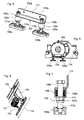
- Fig. 9 a side view of the doffer motor in the machine longitudinal direction.
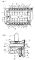
- FIG. 1 shows a schematic plan view of a ring spinning machine 1 with an endless conveyor guided around the ring spinning machine.
- the ring spinning machine 1 has on opposite machine sides parallel to each other spinning stations groups 12a and 12b, each consisting of only schematically indicated spinning stations 11.
- the same as possible Spinnstellenabstand is designated 9. Further details of the ring spinning machine 1, in particular the machine heads are not shown, because it is so far the usual and known arrangements. The number of spinning units 11 is reproduced greatly reduced for the sake of clarity.
- the two spinning station groups 12a, 12b is designed as an endless conveyor conveyor 8 guided around in the form of a vertically extending steel strip.
- the steel strip is placed around deflection rollers 13, 14, 15, 16 with a vertical axis at the two ends of the parallel and in alignment with each other spin groups 12a, 12b.
- deflection rollers 13, 14, 15, 16 with a vertical axis at the two ends of the parallel and in alignment with each other spin groups 12a, 12b.
- the conveying means 8 designed as a vertical steel belt, aligned with the individual spinning stations 11, are fastened to the outside from the endless conveyor 8, each having a carrier finger 5 extending perpendicularly to the conveying direction.
- the mounting rails need not be guided around the ring spinning machine.
- the driver 3 pin slide 2 which according to FIG. 2 of a circular disk-shaped sliding body 6 (plate) and a vertically disposed sleeve pin 4 consist of plastic are preferably made in one piece , And preferably in the region of an arranged between the sleeve pin 4 and the slider 6 widened foot 18 are engaged behind by the drivers 3.
- sleeve changing devices 10 On both sides of the machine indicated by dashed lines in Fig. 1 sleeve changing devices 10 are indicated, which may be formed as in classic Doffern and serve to remove from the spindles of the spinning units 11 full sleeves (cops or coils) and instead choirstecken empty tubes on the spindles, which means the endless conveyor 8 have been brought to the individual spinning stations 11.
- the guide rollers 15, 16 are connected by a in the direction of the double arrows in the machine longitudinal direction movably held clamping bar 17 with each other, which is set by a supported on the machine frame clamping device under the endless conveyor 8 exciting bias.
- a cleaning station with blowing or suction nozzles and / or brushes to clean the driver 3 and the conveyor belt 8 of fiber fly.
- a cleaning element for example in the form of a plaster disk to be mounted, which slides on a circulation of the endless conveyor 8 on the support rail 7 along and cleans them.
- a conveying connection (not shown) to a winding unit or a cop removing and receiving unit can be provided.
- the guide rail 7 is arranged on or on the machine frame.
- the preferably formed as a hollow profile guide rail 7 comprises a flat, horizontally oriented guide or support surface 29, on which a band-shaped plastic slide pad 20 is arranged, on which the pin slide 2 slidably rests with his slider 6 and is guided (Fig. 2).
- the plastic sliding pad 20 has on both sides longitudinally running U-shaped bent sections 28a, 28b, which respectively engage around a guide longitudinal strip 19a, 19b on the guide rail 7 in a form-fitting manner and thus fix the plastic sliding pad 20 on the guide rail 7.
- the pin slide 2 has between the pin 4 and the slider 6 a slightly opposite the pin 4 widened foot 18, which is engaged behind by a driver finger 5.
- the driver finger 5 is connected via a holding arm with the main body of the driver 3, which is fastened with fastening means 24 on the vertical conveyor belt 8. From the opposite side of the foot 18 is acted upon by a jaw (not shown), which is attached via a spring on the support arm or directly to the driver 3. As a result, the pin slides 2 are also guided laterally.
- the guide rail 7 further includes a rearwardly extending guide projection 21 having upper and lower curved guide surfaces 22, 23 formed as vertically extending guide beads extending in the machine longitudinal direction. These are structurally combined with the guide rail 7.
- the driver 3 In its front region, the driver 3 has a guide recess 25 which extends in the longitudinal direction of the machine and is bounded above and below by the guide surfaces 22, 23 which engage around correspondingly curved resilient tongues 26, 27.
- the guide surfaces 22, 23 are complementary to the mating surfaces in the manner shown in FIG. 2 rounded off. In this way, the driver 3 is aligned relative to the machine frame exactly and tilt-proof and only in the longitudinal direction of the machine, which is perpendicular to the plane of the drawing of Fig. 2, defined slidably in the sliding seat.
- the guide beads form-fitting embracing plastic slide pad 30 is applied.
- the example according to FIG. 2 can also be designed without a plastic sliding pad 30.
- the driver 3 is displaced accordingly and slides in the longitudinal direction of the machine on the guide rail 7.
- the driving finger 5 takes with the peg slide 2 with a movement of the conveyor belt 8, which is unguided except on the pulleys , which slides over the bearing surface of the support rail 7 along.
- the guide projection 21 with the guide surfaces 22, 23 is located below the guide surface of the support rail 7 and is approximately at the same height as the conveyor belt 8, so that there is only a comparatively thin body of the driver 3 therebetween
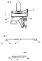
- FIG. 3 shows a further embodiment of a plastic sliding pad 50a, 50b.
- This consists of elongated plastic strips 50a, 50b, which are pressed for attachment to the support rail 47 in longitudinally running, undercut grooves in the support surface of the support rail 47.
- the slide carriages 42 which are guided via drivers 43 slide on these plastic sliding supports 50a, 50b projecting like rails from the support surface of the carrier rail.
- the plastic sliding pad can also be designed as a plastic band with projections for pressing in grooves of a mounting rail.
- the plastic sliding pad consists of a flat plastic band 67 fastened laterally by means of clamps 69a, 69b on the bearing surface of the mounting rail 70.
- FIG. 5 shows a band-shaped plastic sliding pad 87 according to FIG. 2 in cross-section.
- the plastic slide backing 87 has laterally longitudinal U-shaped, resilient bending sections 81a, 81b with essentially horizontally extending end sections.
- the bending section 81a lying toward the doffer has, following the essentially horizontal end section, an obliquely downwardly directed tongue 82, which serves as an assembly aid.
- the angle of the tongue 82 is designed so that it protrudes in the mounted state of the guide rail 19 a and so well tangible
- the plastic sliding pad 20, 87 is hooked during assembly with its inner bending portion 28 b, 81 b in the guide rail 19 b and lowered onto the support surface 29.
- the plastic sliding pad 20, 87 is clipped with its outer bending portion 28a on the guide bar 19a, wherein the bending portion 28a is temporarily resiliently expanded by means of the handle 82 on the tongue 82 for the purpose of over-slipping over the guide bar.
- Said drive serves to move a lifting device, in particular a scissor lever system with gripper bars. He stands in a known manner via a gearbox with a threaded spindle in operative connection, via which the gripper bar is raised or lowered by horizontal guidance of the scissor lever.
- the drive is rigidly attached to the machine frame.
- the transmission of the drive power is done via a not described in detail here transmission with z.
- the operating principle of said Doffers is z. B. in the published patent application DE 42 10 494 B4 and DE 42 05 215 C2 explained in more detail.
- the drive which is preferably an electric motor
- the drive is additionally supported on the floor via spring-loaded support means in order to damp vibration.
- the fasteners may be designed so that the mass weight of the electric motor is largely borne either by the machine frame or by the supporting device.
- the drive is preferably aligned with its shaft in the longitudinal direction of the spinning machine and on the side on which the transmission decreases the drive power from the shaft attached to the machine frame. Accordingly, the drive is preferably resilient on the opposite side in the longitudinal direction of the spinning machine side supported.
- the support device preferably includes means for adjusting the height of the support legs, means for adjusting the suspension hardness and / or means for adjusting the spring travel.
- the drive 101 in the form of an electric motor is connected via its housing, on the one hand, to the machine frame 103 and, on the other hand, to a supporting device 102 and supported by the latter on the ground (FIGS. 8 and 9).
- the drive 101 is preferably fastened to a profile section, in particular to a cross member or intermediate plate or to a cross member 104 within the machine frame 103.
- Gear elements which are in operative connection with a shaft of the electric motor (not shown) are preferably also attached to this traverse or the like.
- the electric motor is aligned with its shaft in the machine longitudinal direction 114.
- the supporting device 102 comprises two support feet 105a, 105b which are spaced apart from one another and are connected to one another via a transverse profile 111.
- the transverse profile 111 is formed in the form of an angle profile and contains openings 112a, 112b for fixing the transverse profile on the housing of the electric motor 101, z. B. by means of screw.
- the support device 102 includes two disc springs 108 held relative to each other for the purpose of vibration damping assemblies.
- the first assembly comprises a support foot 105a, 105b which is connected to a cylindrical support leg 113a, 113b.
- the support leg 113a, 113b includes an annular disc 115 held by means of screws 107a, 107b on the support leg 113a, 113b, on which plate spring elements 108 are mounted.
- the second assembly comprises the transverse profile 111 with the connection points 112a, 112b for the drive 101.
- a cylindrical guide bush 106a, 106b which is open towards the bottom is arranged which laterally guides the plate spring elements and the annular disk 115.
- the guide bushing 106a, 106b may be attached to the transverse profile 111 or designed as an independent component.
- the support leg 113a, 113b is passed through the annular disc 115 and the disc spring elements 108, leaves the guide bush 106a, 106b through an upper hole opening and leads through an opening in the transverse profile 111.
- the support leg 113a, 113b is mounted relative to the guide bushing 106a, 106b, the transverse profile 111 and the plate spring elements 108 so as to be displaceable relative to one another.
- the support leg 113a, 113b preferably includes a height adjustment device, which allows to adjust the distance between the support foot 105a, 105b and cross profile 111 and, correspondingly, the height position of the transverse profile 111 relative to the ground.
- the height adjustment device may for example be provided on the support foot 105a, 105b or on the transverse profile 111 and comprise a known screw mechanism.
- Themaynverstelleinheimtung can also be formed by a guided in the support leg 113a, 143b further profile, which leads to the support foot and a screw mechanism relative to the support leg 113a, 113b is height adjustable.
- the vertical vibrations of the electric motor caused during operation are transmitted via the transverse profile 111 to the guide bushes 106a, 106b, which in turn act on the disc springs 108 and compress them by the vibration-related downward movement and relax upward movement.
- the guide bushes 106a, 106b thus perform a relative movement to the plate spring elements 108 supporting annular disc 115 on the support leg.
- the height of the annular disc 115 and thus the spring hardness can be adjusted.
- the sprung support devices absorb vibrations generated by the doffer drive and ensure that they are not introduced into the machine frame and cause vibrations there.
Landscapes
- Engineering & Computer Science (AREA)
- Mechanical Engineering (AREA)
- Textile Engineering (AREA)
- Spinning Or Twisting Of Yarns (AREA)
- Replacing, Conveying, And Pick-Finding For Filamentary Materials (AREA)
Priority Applications (4)
| Application Number | Priority Date | Filing Date | Title |
|---|---|---|---|
| DE200650006402 DE502006006402D1 (de) | 2006-09-29 | 2006-09-29 | Spulen- bzw. Hülsentransportvorrichtung einer Spinnmaschine |
| EP20060020555 EP1905875B1 (fr) | 2006-09-29 | 2006-09-29 | Dispositif de transport de bobines pour un métier à filer |
| CN2007101545104A CN101153419B (zh) | 2006-09-29 | 2007-09-17 | 用于纺纱机的纱筒和纱管输送装置 |
| JP2007257973A JP2008088623A (ja) | 2006-09-29 | 2007-10-01 | ボビンもしくは巻管搬送装置 |
Applications Claiming Priority (1)
| Application Number | Priority Date | Filing Date | Title |
|---|---|---|---|
| EP20060020555 EP1905875B1 (fr) | 2006-09-29 | 2006-09-29 | Dispositif de transport de bobines pour un métier à filer |
Publications (2)
| Publication Number | Publication Date |
|---|---|
| EP1905875A1 true EP1905875A1 (fr) | 2008-04-02 |
| EP1905875B1 EP1905875B1 (fr) | 2010-03-10 |
Family
ID=37846229
Family Applications (1)
| Application Number | Title | Priority Date | Filing Date |
|---|---|---|---|
| EP20060020555 Ceased EP1905875B1 (fr) | 2006-09-29 | 2006-09-29 | Dispositif de transport de bobines pour un métier à filer |
Country Status (4)
| Country | Link |
|---|---|
| EP (1) | EP1905875B1 (fr) |
| JP (1) | JP2008088623A (fr) |
| CN (1) | CN101153419B (fr) |
| DE (1) | DE502006006402D1 (fr) |
Cited By (1)
| Publication number | Priority date | Publication date | Assignee | Title |
|---|---|---|---|---|
| CN112805423A (zh) * | 2018-10-12 | 2021-05-14 | 特吕茨施勒有限及两合公司 | 用于纺织机器的基座 |
Families Citing this family (14)
| Publication number | Priority date | Publication date | Assignee | Title |
|---|---|---|---|---|
| DE102008017256A1 (de) * | 2008-04-04 | 2009-10-08 | Oerlikon Textile Gmbh & Co. Kg | Vorbereitungseinrichtung für Spinnkopse |
| IT1403277B1 (it) * | 2010-12-20 | 2013-10-17 | Savio Macchine Tessili Spa | Dispositivo e procedimento per il controllo e l'alimentazione ad una roccatrice automatica di spole provenienti alla rinfusa dalla filatura |
| CN102704071A (zh) * | 2012-06-09 | 2012-10-03 | 山西经纬合力机械制造有限公司四厂 | 细纱机中的粗纱循环装置 |
| CN102719943B (zh) * | 2012-06-21 | 2014-08-13 | 青岛城阳华祥纺织机械厂 | 环锭纺自动落纱机行走装置 |
| CN103726144A (zh) * | 2013-12-27 | 2014-04-16 | 浙江日发纺织机械股份有限公司 | 转杯纺纱机纸管输送存储装置 |
| CH710526A2 (de) * | 2014-12-16 | 2016-06-30 | Rieter Ag Maschf | Transporteinrichtung für leere oder bewickelte Hülsen einer Spinnmaschine. |
| CN105316817A (zh) * | 2015-11-04 | 2016-02-10 | 经纬纺织机械股份有限公司 | 一种环锭细纱机集体落纱齿块钢带导向机构 |
| CN105506797B (zh) * | 2016-01-12 | 2023-08-01 | 经纬智能纺织机械有限公司 | 环锭细纱机集体落纱满纱提升同步装置 |
| CN109457341B (zh) * | 2016-12-06 | 2021-08-06 | 海宁市盛祥线业有限公司 | 一种纱线包覆机上的纱锭驱动机构 |
| IT201600127912A1 (it) * | 2016-12-19 | 2018-06-19 | Savio Macch Tessili Spa | Apparato di filatura di tipo open-end e metodo di scarico di una rocca da un apparato di filatura di tipo open-end |
| DE102017105034A1 (de) * | 2017-03-09 | 2018-09-13 | Maschinenfabrik Rieter Ag | Spinnereimaschine |
| DE102017106319A1 (de) * | 2017-03-23 | 2018-09-27 | Maschinenfabrik Rieter Ag | Spinnereimaschine sowie ein Verfahren zum Betreiben von Hülsentransportvorrichtungen an einer Spinnereimaschine |
| CN110217649B (zh) * | 2019-07-04 | 2020-12-29 | 海宁市冯氏科技股份有限公司 | 一种纱筒更换装置中的取筒机构 |
| KR102198836B1 (ko) * | 2019-07-29 | 2021-01-05 | 고재갑 | 정방기용 보빈 스핀들의 이탈방지장치 |
Citations (4)
| Publication number | Priority date | Publication date | Assignee | Title |
|---|---|---|---|---|
| DE3729130A1 (de) * | 1987-09-01 | 1989-03-09 | Schlafhorst & Co W | Einrichtung zum transport von kopsen und huelsen |
| DE3924712A1 (de) * | 1989-07-26 | 1991-01-31 | Zinser Textilmaschinen Gmbh | Transportvorrichtung zum bereitstellen von leeren spulenhuelsen an die spinnstellen und zum abtransportieren von vollen spinnspulen von den spinnstellen einer doppelseitigen spinnmaschine |
| EP0450662A1 (fr) * | 1988-09-24 | 1991-10-09 | Maschinenfabrik Rieter Ag | Métier à filer |
| EP0518817A1 (fr) * | 1991-06-02 | 1992-12-16 | Maschinenfabrik Rieter Ag | Transport de bobines et tubes de bobine dans les métiers à filer |
-
2006
- 2006-09-29 DE DE200650006402 patent/DE502006006402D1/de active Active
- 2006-09-29 EP EP20060020555 patent/EP1905875B1/fr not_active Ceased
-
2007
- 2007-09-17 CN CN2007101545104A patent/CN101153419B/zh active Active
- 2007-10-01 JP JP2007257973A patent/JP2008088623A/ja not_active Withdrawn
Patent Citations (4)
| Publication number | Priority date | Publication date | Assignee | Title |
|---|---|---|---|---|
| DE3729130A1 (de) * | 1987-09-01 | 1989-03-09 | Schlafhorst & Co W | Einrichtung zum transport von kopsen und huelsen |
| EP0450662A1 (fr) * | 1988-09-24 | 1991-10-09 | Maschinenfabrik Rieter Ag | Métier à filer |
| DE3924712A1 (de) * | 1989-07-26 | 1991-01-31 | Zinser Textilmaschinen Gmbh | Transportvorrichtung zum bereitstellen von leeren spulenhuelsen an die spinnstellen und zum abtransportieren von vollen spinnspulen von den spinnstellen einer doppelseitigen spinnmaschine |
| EP0518817A1 (fr) * | 1991-06-02 | 1992-12-16 | Maschinenfabrik Rieter Ag | Transport de bobines et tubes de bobine dans les métiers à filer |
Cited By (2)
| Publication number | Priority date | Publication date | Assignee | Title |
|---|---|---|---|---|
| CN112805423A (zh) * | 2018-10-12 | 2021-05-14 | 特吕茨施勒有限及两合公司 | 用于纺织机器的基座 |
| CN112805423B (zh) * | 2018-10-12 | 2022-06-28 | 特吕茨施勒集团欧洲公司 | 用于纺织机器的基座 |
Also Published As
| Publication number | Publication date |
|---|---|
| JP2008088623A (ja) | 2008-04-17 |
| CN101153419B (zh) | 2011-01-05 |
| CN101153419A (zh) | 2008-04-02 |
| EP1905875B1 (fr) | 2010-03-10 |
| DE502006006402D1 (de) | 2010-04-22 |
Similar Documents
| Publication | Publication Date | Title |
|---|---|---|
| DE102017108572B4 (de) | Lineartransportsystem | |
| EP1905875A1 (fr) | Dispositif de transport de bobines pour un métiers à filer | |
| EP2107143A2 (fr) | Support de bobine ou de tube pour un dispositif de transport de bobine ou de tube sur une machine textile | |
| DE3241924A1 (de) | Vorrichtung zum fuehren von flexiblen versorgungsleitungen | |
| DE1901453A1 (de) | Antrieb fuer schnellaufende Spinnorgane | |
| EP0541850A1 (fr) | Transporteur à palettes curviligne | |
| DE60013439T2 (de) | Förderer für kleiderbügel | |
| DE69201379T2 (de) | Galette. | |
| EP3446953B1 (fr) | Dispositif de transport permettant de transporter des pièces à usiner dans une installation de traitement de surface | |
| DD287538A5 (de) | Haengefoerdersystem | |
| WO1995025056A1 (fr) | Convoyeur aerien a simple voie ou a double voie | |
| DE202007011954U1 (de) | Streckwerk und Unterwalzen-Lagerschlitten | |
| EP0506994A1 (fr) | Transporteur à rouleaux entraîné par courroie | |
| DE19947806B4 (de) | Kettenziehmaschine zum kontinuierlichen Ziehen von Ziehgut | |
| CH689920A5 (de) | Vorrichtung zum Ent- und Versorgen einer Kreuzspulen herstellenden Maschine. | |
| DE3407804A1 (de) | Spulentransportvorrichtung | |
| DE3510955A1 (de) | Selbsttaetige transportvorrichtung fuer eine haengefoerdervorrichtung | |
| DE102012103531B4 (de) | Textilmaschine mit einer Aufnahmevorrichtung für eine zweite Schleppkettenführung | |
| EP1673497A1 (fr) | Banc d'etirage comprenant des cylindres superieurs delivreurs jumeles, autour desquels passent des lanieres | |
| EP2437992B1 (fr) | Dispositif de transport destiné à transporter des marchandises | |
| DE10044612A1 (de) | Kippstation für Stückgutförderer | |
| DE19612708A1 (de) | Spinnmaschine mit Endlosförderer für Hülsenzapfen tragende Zapfenträger | |
| DE19540177C2 (de) | Fördersystem | |
| DE102020102828A1 (de) | Raupenantrieb für Lagerfahrzeug | |
| EP2546175B1 (fr) | Dispositif de transport |
Legal Events
| Date | Code | Title | Description |
|---|---|---|---|
| PUAI | Public reference made under article 153(3) epc to a published international application that has entered the european phase |
Free format text: ORIGINAL CODE: 0009012 |
|
| AK | Designated contracting states |
Kind code of ref document: A1 Designated state(s): AT BE BG CH CY CZ DE DK EE ES FI FR GB GR HU IE IS IT LI LT LU LV MC NL PL PT RO SE SI SK TR |
|
| AX | Request for extension of the european patent |
Extension state: AL BA HR MK YU |
|
| 17P | Request for examination filed |
Effective date: 20080819 |
|
| 17Q | First examination report despatched |
Effective date: 20081006 |
|
| AKX | Designation fees paid |
Designated state(s): CH DE LI |
|
| GRAP | Despatch of communication of intention to grant a patent |
Free format text: ORIGINAL CODE: EPIDOSNIGR1 |
|
| GRAS | Grant fee paid |
Free format text: ORIGINAL CODE: EPIDOSNIGR3 |
|
| GRAA | (expected) grant |
Free format text: ORIGINAL CODE: 0009210 |
|
| AK | Designated contracting states |
Kind code of ref document: B1 Designated state(s): CH DE LI |
|
| REG | Reference to a national code |
Ref country code: CH Ref legal event code: EP |
|
| REF | Corresponds to: |
Ref document number: 502006006402 Country of ref document: DE Date of ref document: 20100422 Kind code of ref document: P |
|
| PLBE | No opposition filed within time limit |
Free format text: ORIGINAL CODE: 0009261 |
|
| STAA | Information on the status of an ep patent application or granted ep patent |
Free format text: STATUS: NO OPPOSITION FILED WITHIN TIME LIMIT |
|
| 26N | No opposition filed |
Effective date: 20101213 |
|
| REG | Reference to a national code |
Ref country code: CH Ref legal event code: PL |
|
| PG25 | Lapsed in a contracting state [announced via postgrant information from national office to epo] |
Ref country code: LI Free format text: LAPSE BECAUSE OF NON-PAYMENT OF DUE FEES Effective date: 20100930 Ref country code: CH Free format text: LAPSE BECAUSE OF NON-PAYMENT OF DUE FEES Effective date: 20100930 |
|
| PGFP | Annual fee paid to national office [announced via postgrant information from national office to epo] |
Ref country code: DE Payment date: 20130919 Year of fee payment: 8 |
|
| REG | Reference to a national code |
Ref country code: DE Ref legal event code: R119 Ref document number: 502006006402 Country of ref document: DE |
|
| PG25 | Lapsed in a contracting state [announced via postgrant information from national office to epo] |
Ref country code: DE Free format text: LAPSE BECAUSE OF NON-PAYMENT OF DUE FEES Effective date: 20150401 |