EP1905876B1 - Hochgeschwindigkeitsrundstrickmaschine mit einer Faserabfällenluftblas- und Wärmeabfuhrvorrichtung - Google Patents
Hochgeschwindigkeitsrundstrickmaschine mit einer Faserabfällenluftblas- und Wärmeabfuhrvorrichtung Download PDFInfo
- Publication number
- EP1905876B1 EP1905876B1 EP06121568A EP06121568A EP1905876B1 EP 1905876 B1 EP1905876 B1 EP 1905876B1 EP 06121568 A EP06121568 A EP 06121568A EP 06121568 A EP06121568 A EP 06121568A EP 1905876 B1 EP1905876 B1 EP 1905876B1
- Authority
- EP
- European Patent Office
- Prior art keywords
- air
- floss
- cylinder
- circular knitting
- knitting machine
- Prior art date
- Legal status (The legal status is an assumption and is not a legal conclusion. Google has not performed a legal analysis and makes no representation as to the accuracy of the status listed.)
- Not-in-force
Links
- 241000628997 Flos Species 0.000 title claims abstract description 39
- 238000009940 knitting Methods 0.000 title claims abstract description 38
- 238000007664 blowing Methods 0.000 title claims abstract description 24
- 238000001816 cooling Methods 0.000 abstract description 10
- 230000000694 effects Effects 0.000 abstract description 9
- 239000004744 fabric Substances 0.000 description 4
- 238000007796 conventional method Methods 0.000 description 2
- 238000009825 accumulation Methods 0.000 description 1
- 230000005465 channeling Effects 0.000 description 1
- 238000010276 construction Methods 0.000 description 1
- 230000007547 defect Effects 0.000 description 1
- 230000002950 deficient Effects 0.000 description 1
- 238000012986 modification Methods 0.000 description 1
- 230000004048 modification Effects 0.000 description 1
- 238000004804 winding Methods 0.000 description 1
Images





Classifications
-
- D—TEXTILES; PAPER
- D04—BRAIDING; LACE-MAKING; KNITTING; TRIMMINGS; NON-WOVEN FABRICS
- D04B—KNITTING
- D04B35/00—Details of, or auxiliary devices incorporated in, knitting machines, not otherwise provided for
- D04B35/30—Devices for controlling temperature of machine parts
Definitions
- the present invention relates to a high speed circular knitting machine having a floss blowing and heat dissipating apparatus according to the preamble of claim 1.
- Operation of a conventional circular knitting machine generally includes the steps of yarn supplying, knitting and fabric winding.
- the cylinder rotates about the center of the circular knitting machine.
- cams surrounding the cylinder that have tracks to direct needles located in the needle troughs of the cylinder to move up and down.
- sinkers are moved forwards in correspondance to the needles to proceed with the knitting operation.
- the supplying yarns In order to smooth the knitting operation, the supplying yarns must be stretched tightly.
- the yarns often generate lint or floss during operations of yarn sinking, yarn directing and yarn feeding. If the floss is not removed, it tends to clog various elements of the circular knitting machine and affect the smoothness of knitting operation, and even shorten the life span of the circular knitting machine.
- U.S. patent No. 5,737,942 entitled “MEANS FOR DETERRING LINT AND DEBRIS ACCUMULATION ON THE KNITTING ELEMENTS OF A CIRCULAR KNITTING MACHINE” has a curved plate interposed between a horizontal frame plate and a circular frame plate and a straddle seat to form an air chamber. Through an air pump and an air supply hose, pressurized air is delivered into the air chamber. The pressurized air is dispersed naturally to the cylinder and other elements through an annular gap formed between the straddle seat and the circular frame plate to blow away the floss and achieve a cooling effect.
- U.S. patent No. 6,199,408 entitled “Cooling apparatus for knitting components” includes a cover located between an intermediate ring and a lower ring, and a cylindrical chamber formed between a needle-selecting actuator and the cover. There is a ventilator fan located on the cover to draw external air into the chamber. Channeling by an opening of the chamber enables dispelling heat generated on the cylinder and the surrounding operation elements.
- U.S. patent No. 5,737,942 but fares even worse in terms of the effect of floss blowing and cooling effect. All the problems of the conventional techniques, such as poor floss blowing and cooling effect, and overloading of the air pump, are still pending to be resolved.
- a high speed circular knitting machine having a floss blowing and heat dissipating apparatus.
- the high speed circular knitting machine has a plurality of air vents to converge pressurized air to generate strong airflow to blow away the floss from those locations where the floss most likely accumulates such as the straddle seats, cylinder and needles.
- usage of the pressurized air can be reduced, and the life span of the airflow generator can be extended.
- Temperature generated due to friction between the cylinder troughs and needles is lower. An optimal cooling effect can be achieved.
- the floss blowing and heat dissipating apparatus for high speed circular knitting machines has a cylinder in a circular knitting machine rotating about a axis in the center.
- the cylinder has a plurality of needle troughs. Each needle trough holds a needle or a sinker.
- the cylinder is surrounded by a circular frame plate mounted onto a frame plate bracket and a plurality of straddle seats mounted onto a horizontal frame plate. Each of the straddle seats has a cam to guide and direct the needle to move up and down to perform a knitting operation.
- the floss blowing and heat dissipating apparatus includes an airflow generator to generate pressurized air which is delivered through an air directing hose, and a plurality of annular ducts located on the periphery of the cylinder and the straddle seats.
- the annular ducts have a passage with openings on two ends and a plurality of air vents close to the cylinder and the straddle seats.
- the air vents communicate with the passage.
- At least one air intake connector is provided to bridge the annular ducts to channel the pressurized air to the passage. Thereby the pressurized air can be ejected through the air vents and blow forcefully towards the straddle seats, cylinder and needles to carry away the floss and heat accumulated thereon.
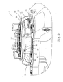
- FIGS. 1 through 6 Please refer to FIGS. 1 through 6 for a first embodiment of a circular knitting machine having a floss blowing and heat dissipating apparatus according to the invention.
- the circular knitting machine 1 has a cylinder 16 which can rotate about a center axis.
- the cylinder 16 has a plurality of needle troughs 18, and each of the needle troughs 18 holds a needle 17 or a sinker (not shown in the drawings).
- the cylinder 16 is surrounded by a circular frame plate 13 mounted onto a frame plate bracket 12 and a plurality of straddle seats 11 mounted onto a horizontal frame plate 14.
- the frame plate bracket 12 is mounted onto a holding ring 15.
- Each of the straddle seats 11 has a cam (not shown in the drawings).
- the floss blowing and heat dissipating apparatus 10 includes an airflow generator 60 which may be a blower or an air pump to generate pressurized air to be delivered through an air directing hose 61, a plurality of annular ducts 20 which are located on the periphery of the cylinder 16 and straddle seats 11, and mounted beneath the circular frame plate 13 through an anchor rack 21.
- the annular ducts 20 have a passage 40 with two open ends.
- the annular ducts 20 close to the cylinder 16 and straddle seats 11 have a plurality of air vents 22 communicating with the passage 40.
- At least one air intake connector 30 is provided to bridge the annular ducts 20.
- the air intake connector 30 has an air inlet 31 to channel the pressurized air into the passage 40.
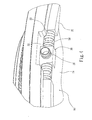
- the junctures of the air intake connector 30 and the annular ducts 20 have connection ports 32 and 33 that are coupled through a connection duct 50 (referring FIG. 4 ). Aside from connecting the annular ducts 20 through the air intake connector 30, they also may be coupled directly through the connection duct 50.
- the pressurized air can be ejected forcefully through the air vents 22 towards the straddle seats 11, cylinder 16 and needles 17 to carry away the accumulating floss and heat.
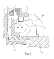
- the pressurized air ejected through the air vents 22 mainly is directed to an upper inclined surface of the straddle seats 11 so that the pressurized air can be diverted or refracted upwards towards the cylinder 16 and needles 17 to carry away the floss and heat accumulating on the straddle seats 11, cylinder 16 and needles 17.
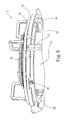
- FIG. 8 for a second embodiment which serves to improve the understanding of the invention.
- the embodiment differs from the first embodiment in that the air inlet 31 is formed directly on one annular duct 20, and in that the annular ducts 20 are coupled tightly by a connection duct 50. Hence the pressurized air can be ejected forcefully through the air vents 22 towards the straddle seats 11, cylinder 16 and needles 17 to carry away the floss and heat accumulating thereon.
- FIG. 9 for a third embodiment which serves to improve the understanding of the invention.
- This embodiment differs from the first embodiment in that only one annular duct 20 is provided beneath the circular frame plate 13.
- the annular duct 20 also has an air inlet 31 to channel the pressurized air to the air vents 22 for ejection forcefully towards the straddle seats 11, cylinder 16 and needles 17 to carry away the floss and heat accumulating thereon.
Landscapes
- Engineering & Computer Science (AREA)
- Textile Engineering (AREA)
- Knitting Machines (AREA)
- Treatment Of Fiber Materials (AREA)
Claims (6)
- Hochgeschwindigkeits-Rundstrickmaschine mit einer Faserabfälle-Blasvorrichtung und Wärmeabführvorrichtung, welche Hochgeschwindigkeits-Rundstrickmaschine (1) einen Zylinder (16) aufweist, der sich um eine zentrale Achse dreht, wobei der Zylinder (16) eine Mehrzahl von Nadelwannen, die jeweils eine Stricknadel (17) oder eine Einschließplaline aufnehmen und von einem kreisförmigen Rahmenblech (13) umgeben sind, das auf einen Rahmenblech-Träger (12) montiert ist, und eine Mehrzahl von Klammersitzen (11) aufweist, die auf ein horizontales Rahmenbleeh (14) montiert sind, wobei jeder der Klammersitze (11) einen Nocken- bzw. Steuerkörper aufweist, um die Nadel (17) aufwärts und abwärts zu treiben, während sich der Zylinder (16) dreht, um einen Strickvorgang auszuführen, welche Faserablälle-Blasvorrichtung und Wärmeabführvorrichtung umfasst:einen Luftströmungserzeuger (60), um Druckluft zu erzeugen, die über einen Lulileitschlauch (61) angegeben wird; undeine Mehrzahl von ringförmigen Röhren (20), die sich auf dem Umfang des Zylinders (16) und den Klammersitzen (11) befinden und einen Kanal (40) aufweisen, der zwei offene Enden aufweist, und die eine Mehrzahl von Luftauslasslöehem (22) auf den ringförmigen Röhren (20) in der Nähe des Zylinders (16) und der Klammersitze (11) aufweisen, welche mit dem Kanal (40) in Verbindung stehen;dadurch gekennzeichnet, dass die Faserabllille-Blasvonichtung und Wärmeabführvorrichtung außerdem zumindest ein Lufteinlass-Verbindungsstück (30) umfasst, welches die ringförmigen Röhren (20) miteinander verbindet und einen Lufteinlass (31) aufweist, um die Druckluft in den Kanal (40) durchzulassen;
wobei die Druckluft über die Luflauslasslöcher (22) ausgestoßen wird, um kräftig gegen die Klammersitze (11), den Zylinder (16) und die Nadeln (17) zu blasen, um Faserabfälle und eine Wärmeansammlung darauf zu beseitigen. - Hochgeschwindigkeits-Rundstrickmaschine mit einer Faserabfälle-Blasvorrichtung und Warmeabführvorrichtung nach Anspruch 1, wobei das Lufteinlass-Verbindungsstück (30) und die ringförmigen Röhren (20) über ein Verbindungsrohr (50) miteinander verbunden sind.
- Hochgeschwindigkeits-Rundstrickmaschine mit einer Faserablälle-Blasvorrichtung und Wärmeablührvarrichtung nach Anspruch 1, wobei die ringförmigen Röhren (20) über ein Verbindungsrohr (50) miteinander verbunden sind.
- HochgeschwindigkeiLs-Rundstrickmaschine mit einer Faserabfälle-Blasvorrichtung und Wärmeabführvorrichtung nach einem der vorherigen Ansprüche, wobei die Druckluft, die über die Luftauslasslöcher (22) ausgestoßen wird, auf eine obere geneigte Fläche der Klammersitze (11) gerichtet ist, so dass die Druckluft aufwärts zu dem Zylinder (16) und der Nadel (17) umgelenkt wird, um die Faserabfälle und Wärmeansammlung darauf abzuführen.
- Hochgeschwindigkeit,-Rundstrickmaschine mit einer Fascrabfälle-Blasvorrichtung und Wärmeabführvorrichtung nach einem der vorherigen Ansprüche, wobei die ringförmigen Röhren (20) unterhalb des kreisförmigen Rahmenblechs (13) mit Hilfe eines Befestigungsgestells (21) montiert sind.
- Hochgeschwindigkeits-Rundstrickmaschine mit einer Fascrabfälle-Blasvorrichtung und Wärmeabführvorrichtung nach einem der vorhergehenden Ansprüche, wobei der Luftströmungserzeuger (60) wahlweise ein Gebläse oder eine Luftpumpeinrichtung ist.
Priority Applications (3)
| Application Number | Priority Date | Filing Date | Title |
|---|---|---|---|
| EP06121568A EP1905876B1 (de) | 2006-09-29 | 2006-09-29 | Hochgeschwindigkeitsrundstrickmaschine mit einer Faserabfällenluftblas- und Wärmeabfuhrvorrichtung |
| AT06121568T ATE448344T1 (de) | 2006-09-29 | 2006-09-29 | Hochgeschwindigkeitsrundstrickmaschine mit einer faserabfällenluftblas- und wärmeabfuhrvorrichtung |
| DE602006010394T DE602006010394D1 (de) | 2006-09-29 | 2006-09-29 | Hochgeschwindigkeitsrundstrickmaschine mit einer Faserabfällenluftblas- und Wärmeabfuhrvorrichtung |
Applications Claiming Priority (1)
| Application Number | Priority Date | Filing Date | Title |
|---|---|---|---|
| EP06121568A EP1905876B1 (de) | 2006-09-29 | 2006-09-29 | Hochgeschwindigkeitsrundstrickmaschine mit einer Faserabfällenluftblas- und Wärmeabfuhrvorrichtung |
Publications (2)
| Publication Number | Publication Date |
|---|---|
| EP1905876A1 EP1905876A1 (de) | 2008-04-02 |
| EP1905876B1 true EP1905876B1 (de) | 2009-11-11 |
Family
ID=37497874
Family Applications (1)
| Application Number | Title | Priority Date | Filing Date |
|---|---|---|---|
| EP06121568A Not-in-force EP1905876B1 (de) | 2006-09-29 | 2006-09-29 | Hochgeschwindigkeitsrundstrickmaschine mit einer Faserabfällenluftblas- und Wärmeabfuhrvorrichtung |
Country Status (3)
| Country | Link |
|---|---|
| EP (1) | EP1905876B1 (de) |
| AT (1) | ATE448344T1 (de) |
| DE (1) | DE602006010394D1 (de) |
Families Citing this family (1)
| Publication number | Priority date | Publication date | Assignee | Title |
|---|---|---|---|---|
| CN114351346A (zh) * | 2022-01-17 | 2022-04-15 | 信泰(福建)科技有限公司 | 一种编织设备定向恒温装置及编织设备 |
Family Cites Families (4)
| Publication number | Priority date | Publication date | Assignee | Title |
|---|---|---|---|---|
| DD159439B1 (de) * | 1981-06-04 | 1986-08-13 | Dieter Rothe | Vorrichtung zum abblasen von staub- und flusen fuer strickmaschinen, insbesondere rundstrickmaschinen |
| US5737942A (en) * | 1996-07-03 | 1998-04-14 | Alandale Industries, Inc. | Means for deterring lint and debris accumulation on the knitting elements of a circular knitting machine |
| JP2000008258A (ja) * | 1998-06-16 | 2000-01-11 | Precision Fukuhara Works Ltd | 編成部品冷却装置 |
| DE102004049001A1 (de) * | 2004-10-06 | 2006-04-13 | Sipra Patententwicklungs- Und Beteiligungsgesellschaft Mbh | Rundstrickmaschine mit einer Entstaubungseinrichtung |
-
2006
- 2006-09-29 AT AT06121568T patent/ATE448344T1/de not_active IP Right Cessation
- 2006-09-29 DE DE602006010394T patent/DE602006010394D1/de active Active
- 2006-09-29 EP EP06121568A patent/EP1905876B1/de not_active Not-in-force
Also Published As
| Publication number | Publication date |
|---|---|
| ATE448344T1 (de) | 2009-11-15 |
| DE602006010394D1 (de) | 2009-12-24 |
| EP1905876A1 (de) | 2008-04-02 |
Similar Documents
| Publication | Publication Date | Title |
|---|---|---|
| EP0742852B1 (de) | Verfahren und vorrichtung zur herstellung von faserband-hochflor-gestrick mit umgekehrten schlaufen | |
| US5737942A (en) | Means for deterring lint and debris accumulation on the knitting elements of a circular knitting machine | |
| KR102295703B1 (ko) | 린트제거장치를 구비한 환편기 | |
| EP0510508B1 (de) | Vorrichtung zum Sammeln und Entfernen von Flockenstaub an eine Strickmaschine | |
| JP4858869B2 (ja) | 塵除去デバイスを備えた丸編み機 | |
| JPS6269852A (ja) | 編針及び引下げシンカを持つ丸編機 | |
| US7269977B1 (en) | Floss blowing and heat dissipating apparatus for high speed circular knitting machines | |
| US6199408B1 (en) | Cooling apparatus for knitting components | |
| EP1905876A1 (de) | Faserabfällenluftblas- und Wärmeabfuhrvorrichtung für eine Rundstrickmaschine | |
| CN1869310B (zh) | 缝纫机 | |
| KR100811960B1 (ko) | 고속 원형 편물기용 프로스 브로잉 및 열 분산 장치 | |
| JP2004538392A (ja) | 高速形成ヘッド | |
| CN101153427A (zh) | 高速圆编机的吹絮及散热装置 | |
| JP2007063679A (ja) | 糸条冷却装置 | |
| JP4717583B2 (ja) | スプライサ装置のクリーナー | |
| KR100998345B1 (ko) | 편직기용 사도 조립체 | |
| KR100729963B1 (ko) | 편면 환편기의 섬유 송풍 및 열 소산 시스템 | |
| US20070125131A1 (en) | Knitting machines with air feed | |
| KR101121378B1 (ko) | 원형 편물기용 실 공급 플레이트 양방향 플로스 블로잉 장치 | |
| JP2010511803A (ja) | 解撚繊維質材料を使用して編み地を製造する丸編み機 | |
| EP2343405A1 (de) | Vorrichtung für Rundstrickmaschinen zum beidseitigen Abblasen von Flusen vom Fadenführer | |
| JP3352726B2 (ja) | メリヤス編機用除塵装置 | |
| US7784308B1 (en) | Yarn feeding plate double-sided floss blowing apparatus for circular knitting machines | |
| JP4971090B2 (ja) | ダブル編用丸編機及びダブル生地の編成方法 | |
| EP1559819B1 (de) | Platinen für Rundstrickmaschine für Polware |
Legal Events
| Date | Code | Title | Description |
|---|---|---|---|
| PUAI | Public reference made under article 153(3) epc to a published international application that has entered the european phase |
Free format text: ORIGINAL CODE: 0009012 |
|
| AK | Designated contracting states |
Kind code of ref document: A1 Designated state(s): AT BE BG CH CY CZ DE DK EE ES FI FR GB GR HU IE IS IT LI LT LU LV MC NL PL PT RO SE SI SK TR |
|
| AX | Request for extension of the european patent |
Extension state: AL BA HR MK YU |
|
| AKX | Designation fees paid | ||
| RBV | Designated contracting states (corrected) |
Designated state(s): AT BE BG CH CY CZ LI |
|
| 17P | Request for examination filed |
Effective date: 20070531 |
|
| RBV | Designated contracting states (corrected) |
Designated state(s): AT BE BG CH CY CZ DE DK EE ES FI FR GB GR HU IE IS IT LI LT LU LV MC NL PL PT RO SE SI SK TR |
|
| REG | Reference to a national code |
Ref country code: DE Ref legal event code: 8566 |
|
| RTI1 | Title (correction) |
Free format text: HIGH SPEED CIRCULAR KNITTING MACHINE WITH A FLOSS BLOWING AND HEAT DISSIPATING APPARATUS |
|
| GRAP | Despatch of communication of intention to grant a patent |
Free format text: ORIGINAL CODE: EPIDOSNIGR1 |
|
| GRAS | Grant fee paid |
Free format text: ORIGINAL CODE: EPIDOSNIGR3 |
|
| GRAA | (expected) grant |
Free format text: ORIGINAL CODE: 0009210 |
|
| AK | Designated contracting states |
Kind code of ref document: B1 Designated state(s): AT BE BG CH CY CZ DE DK EE ES FI FR GB GR HU IE IS IT LI LT LU LV MC NL PL PT RO SE SI SK TR |
|
| REG | Reference to a national code |
Ref country code: GB Ref legal event code: FG4D |
|
| REG | Reference to a national code |
Ref country code: CH Ref legal event code: EP |
|
| REG | Reference to a national code |
Ref country code: IE Ref legal event code: FG4D |
|
| REF | Corresponds to: |
Ref document number: 602006010394 Country of ref document: DE Date of ref document: 20091224 Kind code of ref document: P |
|
| NLV1 | Nl: lapsed or annulled due to failure to fulfill the requirements of art. 29p and 29m of the patents act | ||
| LTIE | Lt: invalidation of european patent or patent extension |
Effective date: 20091111 |
|
| PG25 | Lapsed in a contracting state [announced via postgrant information from national office to epo] |
Ref country code: PT Free format text: LAPSE BECAUSE OF FAILURE TO SUBMIT A TRANSLATION OF THE DESCRIPTION OR TO PAY THE FEE WITHIN THE PRESCRIBED TIME-LIMIT Effective date: 20100311 Ref country code: SE Free format text: LAPSE BECAUSE OF FAILURE TO SUBMIT A TRANSLATION OF THE DESCRIPTION OR TO PAY THE FEE WITHIN THE PRESCRIBED TIME-LIMIT Effective date: 20091111 Ref country code: IS Free format text: LAPSE BECAUSE OF FAILURE TO SUBMIT A TRANSLATION OF THE DESCRIPTION OR TO PAY THE FEE WITHIN THE PRESCRIBED TIME-LIMIT Effective date: 20100311 Ref country code: LT Free format text: LAPSE BECAUSE OF FAILURE TO SUBMIT A TRANSLATION OF THE DESCRIPTION OR TO PAY THE FEE WITHIN THE PRESCRIBED TIME-LIMIT Effective date: 20091111 Ref country code: FI Free format text: LAPSE BECAUSE OF FAILURE TO SUBMIT A TRANSLATION OF THE DESCRIPTION OR TO PAY THE FEE WITHIN THE PRESCRIBED TIME-LIMIT Effective date: 20091111 Ref country code: ES Free format text: LAPSE BECAUSE OF FAILURE TO SUBMIT A TRANSLATION OF THE DESCRIPTION OR TO PAY THE FEE WITHIN THE PRESCRIBED TIME-LIMIT Effective date: 20100222 |
|
| PG25 | Lapsed in a contracting state [announced via postgrant information from national office to epo] |
Ref country code: LV Free format text: LAPSE BECAUSE OF FAILURE TO SUBMIT A TRANSLATION OF THE DESCRIPTION OR TO PAY THE FEE WITHIN THE PRESCRIBED TIME-LIMIT Effective date: 20091111 Ref country code: CY Free format text: LAPSE BECAUSE OF FAILURE TO SUBMIT A TRANSLATION OF THE DESCRIPTION OR TO PAY THE FEE WITHIN THE PRESCRIBED TIME-LIMIT Effective date: 20091111 Ref country code: PL Free format text: LAPSE BECAUSE OF FAILURE TO SUBMIT A TRANSLATION OF THE DESCRIPTION OR TO PAY THE FEE WITHIN THE PRESCRIBED TIME-LIMIT Effective date: 20091111 Ref country code: SI Free format text: LAPSE BECAUSE OF FAILURE TO SUBMIT A TRANSLATION OF THE DESCRIPTION OR TO PAY THE FEE WITHIN THE PRESCRIBED TIME-LIMIT Effective date: 20091111 |
|
| PG25 | Lapsed in a contracting state [announced via postgrant information from national office to epo] |
Ref country code: BE Free format text: LAPSE BECAUSE OF FAILURE TO SUBMIT A TRANSLATION OF THE DESCRIPTION OR TO PAY THE FEE WITHIN THE PRESCRIBED TIME-LIMIT Effective date: 20091111 Ref country code: AT Free format text: LAPSE BECAUSE OF FAILURE TO SUBMIT A TRANSLATION OF THE DESCRIPTION OR TO PAY THE FEE WITHIN THE PRESCRIBED TIME-LIMIT Effective date: 20091111 |
|
| PG25 | Lapsed in a contracting state [announced via postgrant information from national office to epo] |
Ref country code: EE Free format text: LAPSE BECAUSE OF FAILURE TO SUBMIT A TRANSLATION OF THE DESCRIPTION OR TO PAY THE FEE WITHIN THE PRESCRIBED TIME-LIMIT Effective date: 20091111 Ref country code: DK Free format text: LAPSE BECAUSE OF FAILURE TO SUBMIT A TRANSLATION OF THE DESCRIPTION OR TO PAY THE FEE WITHIN THE PRESCRIBED TIME-LIMIT Effective date: 20091111 Ref country code: RO Free format text: LAPSE BECAUSE OF FAILURE TO SUBMIT A TRANSLATION OF THE DESCRIPTION OR TO PAY THE FEE WITHIN THE PRESCRIBED TIME-LIMIT Effective date: 20091111 Ref country code: BG Free format text: LAPSE BECAUSE OF FAILURE TO SUBMIT A TRANSLATION OF THE DESCRIPTION OR TO PAY THE FEE WITHIN THE PRESCRIBED TIME-LIMIT Effective date: 20100211 |
|
| PG25 | Lapsed in a contracting state [announced via postgrant information from national office to epo] |
Ref country code: SK Free format text: LAPSE BECAUSE OF FAILURE TO SUBMIT A TRANSLATION OF THE DESCRIPTION OR TO PAY THE FEE WITHIN THE PRESCRIBED TIME-LIMIT Effective date: 20091111 Ref country code: CZ Free format text: LAPSE BECAUSE OF FAILURE TO SUBMIT A TRANSLATION OF THE DESCRIPTION OR TO PAY THE FEE WITHIN THE PRESCRIBED TIME-LIMIT Effective date: 20091111 |
|
| PLBE | No opposition filed within time limit |
Free format text: ORIGINAL CODE: 0009261 |
|
| STAA | Information on the status of an ep patent application or granted ep patent |
Free format text: STATUS: NO OPPOSITION FILED WITHIN TIME LIMIT |
|
| 26N | No opposition filed |
Effective date: 20100812 |
|
| PG25 | Lapsed in a contracting state [announced via postgrant information from national office to epo] |
Ref country code: GR Free format text: LAPSE BECAUSE OF FAILURE TO SUBMIT A TRANSLATION OF THE DESCRIPTION OR TO PAY THE FEE WITHIN THE PRESCRIBED TIME-LIMIT Effective date: 20100212 |
|
| PGFP | Annual fee paid to national office [announced via postgrant information from national office to epo] |
Ref country code: IT Payment date: 20100924 Year of fee payment: 5 |
|
| PGFP | Annual fee paid to national office [announced via postgrant information from national office to epo] |
Ref country code: DE Payment date: 20100929 Year of fee payment: 5 |
|
| PG25 | Lapsed in a contracting state [announced via postgrant information from national office to epo] |
Ref country code: MC Free format text: LAPSE BECAUSE OF NON-PAYMENT OF DUE FEES Effective date: 20100930 |
|
| REG | Reference to a national code |
Ref country code: CH Ref legal event code: PL |
|
| GBPC | Gb: european patent ceased through non-payment of renewal fee |
Effective date: 20100929 |
|
| REG | Reference to a national code |
Ref country code: FR Ref legal event code: ST Effective date: 20110531 |
|
| PG25 | Lapsed in a contracting state [announced via postgrant information from national office to epo] |
Ref country code: CH Free format text: LAPSE BECAUSE OF NON-PAYMENT OF DUE FEES Effective date: 20100930 Ref country code: IE Free format text: LAPSE BECAUSE OF NON-PAYMENT OF DUE FEES Effective date: 20100929 Ref country code: LI Free format text: LAPSE BECAUSE OF NON-PAYMENT OF DUE FEES Effective date: 20100930 Ref country code: FR Free format text: LAPSE BECAUSE OF NON-PAYMENT OF DUE FEES Effective date: 20100930 |
|
| PG25 | Lapsed in a contracting state [announced via postgrant information from national office to epo] |
Ref country code: GB Free format text: LAPSE BECAUSE OF NON-PAYMENT OF DUE FEES Effective date: 20100929 |
|
| PGFP | Annual fee paid to national office [announced via postgrant information from national office to epo] |
Ref country code: TR Payment date: 20110922 Year of fee payment: 6 |
|
| PG25 | Lapsed in a contracting state [announced via postgrant information from national office to epo] |
Ref country code: HU Free format text: LAPSE BECAUSE OF FAILURE TO SUBMIT A TRANSLATION OF THE DESCRIPTION OR TO PAY THE FEE WITHIN THE PRESCRIBED TIME-LIMIT Effective date: 20100512 Ref country code: LU Free format text: LAPSE BECAUSE OF NON-PAYMENT OF DUE FEES Effective date: 20100929 Ref country code: NL Free format text: LAPSE BECAUSE OF FAILURE TO SUBMIT A TRANSLATION OF THE DESCRIPTION OR TO PAY THE FEE WITHIN THE PRESCRIBED TIME-LIMIT Effective date: 20091111 |
|
| PG25 | Lapsed in a contracting state [announced via postgrant information from national office to epo] |
Ref country code: DE Free format text: LAPSE BECAUSE OF NON-PAYMENT OF DUE FEES Effective date: 20130403 |
|
| PG25 | Lapsed in a contracting state [announced via postgrant information from national office to epo] |
Ref country code: IT Free format text: LAPSE BECAUSE OF NON-PAYMENT OF DUE FEES Effective date: 20120929 |
|
| REG | Reference to a national code |
Ref country code: DE Ref legal event code: R119 Ref document number: 602006010394 Country of ref document: DE Effective date: 20130403 |
|
| PG25 | Lapsed in a contracting state [announced via postgrant information from national office to epo] |
Ref country code: TR Free format text: LAPSE BECAUSE OF NON-PAYMENT OF DUE FEES Effective date: 20120929 |