EP1905916B1 - Dispositif de fixation d'objets plats au plafond, particulièrement de feuilles de verre comme protection contre la fumée - Google Patents
Dispositif de fixation d'objets plats au plafond, particulièrement de feuilles de verre comme protection contre la fumée Download PDFInfo
- Publication number
- EP1905916B1 EP1905916B1 EP06024354A EP06024354A EP1905916B1 EP 1905916 B1 EP1905916 B1 EP 1905916B1 EP 06024354 A EP06024354 A EP 06024354A EP 06024354 A EP06024354 A EP 06024354A EP 1905916 B1 EP1905916 B1 EP 1905916B1
- Authority
- EP
- European Patent Office
- Prior art keywords
- clamping
- arrangement
- flat objects
- bolt
- hollow profile
- Prior art date
- Legal status (The legal status is an assumption and is not a legal conclusion. Google has not performed a legal analysis and makes no representation as to the accuracy of the status listed.)
- Not-in-force
Links
- 239000011521 glass Substances 0.000 title description 19
- 239000000779 smoke Substances 0.000 title description 5
- 229910052782 aluminium Inorganic materials 0.000 description 2
- XAGFODPZIPBFFR-UHFFFAOYSA-N aluminium Chemical compound [Al] XAGFODPZIPBFFR-UHFFFAOYSA-N 0.000 description 2
- 238000003780 insertion Methods 0.000 description 2
- 230000037431 insertion Effects 0.000 description 2
- 230000002093 peripheral effect Effects 0.000 description 2
- 229910000831 Steel Inorganic materials 0.000 description 1
- 239000002131 composite material Substances 0.000 description 1
- 238000009434 installation Methods 0.000 description 1
- 229910052751 metal Inorganic materials 0.000 description 1
- 239000002184 metal Substances 0.000 description 1
- 239000004033 plastic Substances 0.000 description 1
- 230000001681 protective effect Effects 0.000 description 1
- 239000005336 safety glass Substances 0.000 description 1
- 239000010959 steel Substances 0.000 description 1
- 239000000725 suspension Substances 0.000 description 1
- 230000007704 transition Effects 0.000 description 1
Images

Classifications
-
- E—FIXED CONSTRUCTIONS
- E04—BUILDING
- E04B—GENERAL BUILDING CONSTRUCTIONS; WALLS, e.g. PARTITIONS; ROOFS; FLOORS; CEILINGS; INSULATION OR OTHER PROTECTION OF BUILDINGS
- E04B9/00—Ceilings; Construction of ceilings, e.g. false ceilings; Ceiling construction with regard to insulation
- E04B9/008—Ceilings; Construction of ceilings, e.g. false ceilings; Ceiling construction with regard to insulation with means for connecting partition walls or panels to the ceilings
-
- F—MECHANICAL ENGINEERING; LIGHTING; HEATING; WEAPONS; BLASTING
- F16—ENGINEERING ELEMENTS AND UNITS; GENERAL MEASURES FOR PRODUCING AND MAINTAINING EFFECTIVE FUNCTIONING OF MACHINES OR INSTALLATIONS; THERMAL INSULATION IN GENERAL
- F16B—DEVICES FOR FASTENING OR SECURING CONSTRUCTIONAL ELEMENTS OR MACHINE PARTS TOGETHER, e.g. NAILS, BOLTS, CIRCLIPS, CLAMPS, CLIPS OR WEDGES; JOINTS OR JOINTING
- F16B2/00—Friction-grip releasable fastenings
- F16B2/02—Clamps, i.e. with gripping action effected by positive means other than the inherent resistance to deformation of the material of the fastening
- F16B2/18—Clamps, i.e. with gripping action effected by positive means other than the inherent resistance to deformation of the material of the fastening using cams, levers, eccentrics, or toggles
Definitions
- the invention relates to a ceiling mounting profile arrangement for flat objects, in particular vertically suspended glass panes as smoke aprons according to the preamble of claim 1.
- a ceiling mounting profile arrangement is already known with a profile rail for supporting the individual elements of suspended false ceilings with an open at the bottom receiving space for accommodating a guide rail for a vertical slatted curtain ( DE 24 35 301 A1 ).
- the profile rail is a rail hollow profile with two horizontal cheeks, of which two legs extend vertically downwards and form between them the downwardly open receiving space, in which the guide rail can be used.
- the guide rail has on its upper side about a vertical axis pivotable holding members in the form of elongated crossbars, which are pivoted by means of screws designed as actuators.
- the crossbars extend in an open position only in a longitudinal slot, through which they can be inserted into a channel of the rail.
- the crossbar on the horizontal cheeks of the rail hollow profile of the rail In a closed position, the crossbar on the horizontal cheeks of the rail hollow profile of the rail. To the underside of the crossbars each a clamping approach is formed, which is pressed in the open position in a respective slot of the guide rail, not to pivot when inserting the guide rail. To be pivotable after insertion, the crossbars are pressed with a screwdriver up and tightened after pivoting in the closed position. - However, the screws are accessible only with the screwdriver, as far as the guide rail inserted into the rail is open at the bottom in a central area, that is not closed or covered by the slatted curtain.
- a rail hollow profile which has internally at least one substantially horizontal cheek, from which a first leg is angled vertically downwards, wherein parallel to the first leg and at a clear distance to this a second substantially vertical leg is provided delimited together with the first leg an interior with a bottom open side.
- the interior is referred to as Klemm Kunststofffactraum, because in it at least one clamping piece can be used, which is adapted to pinch an edge region of the sheet-like object.
- the flat object may in particular be a glass pane or a composite of two glass panes which consists of two glued-together panes and is known by the name VSG pane.
- the panes are dimensioned in particular as smoke aprons, which are to ensure that smoke is limited to one room and does not affect adjacent rooms.
- Such a clamping piece further comprises a latch pivotable about a vertical axis and an actuator of the latch operable on the open side of the clamping piece receiving space.
- the latch can assume two defined positions, an open position and a closed position, to which it is adjusted with the actuating element.
- the latch In the open position, the latch is pivoted so that it does not protrude laterally beyond the clamping piece or only between the legs of the rail hollow profile or in a extends vertically over the legs extended head portion of the rail hollow profile adjacent to the cheek.
- the clamping pieces can be inserted together with the flat object, at the edge region they are clamped in the rail hollow profile, in particular from below, or be removed from this.
- the closed position of the bolt these are pivoted so that they rest on the cheek in the rail hollow profile and thus carry the corresponding clamping piece together with the clamped flat object. After such mounting the flat object protrudes down from the open side of the rail hollow profile.
- the actuating element of the bolt can be pivoted at least in the closed position between the two legs of the rail hollow profile, as will be explained below.
- the open position and the closed position can be set with the bolt already when it rests in the closed position only on a lateral horizontal cheek or is moved away in the open position of this, and if the rail hollow profile and the clamping pieces are dimensioned so that the clamping pieces in the rail hollow valve not tilt significantly despite one-sided support or when the clamping pieces are aligned by adjusting means straight.
- the associated latch is designed and arranged so that it rests in the closed position on both cheeks and thus the object, which is clamped in the clamping pieces, easily vertically aligned.
- the rail profile is in particular for the above symmetrical design with two horizontal cheeks according to claim 9 integrally formed approximately ⁇ -shaped, with the two at a distance from each other arranged legs which define an open bottom side, with the top laterally adjoin the legs horizontal cheeks, over which an extended cavity expands.
- the rail hollow profile is expedient according to claim 10, an extruded aluminum, which is easily manufactured so that it follows the contour of the flat object to be used.
- the bolt of the clamping piece is biased by a spring so that it tries to pivot in the closed position, if no further force or no further moment for manually pivoting the bolt on this acts.
- the cooperating with the latch actuator is designed as a two-armed lever which is pivotable about a horizontal axis on a longitudinal side of the clamping piece, wherein an upper lever arm abuts the latch on such that this by manually pivoting the lever in the open position against the spring force is moved, for which a lower lever arm on the open side of the rail hollow profile can be actuated.
- manual operation may require a tool as indicated below.
- the actuating element particularly advantageously comprises according to claim 2, a knee-shaped lever plate, which is designed and arranged so that the bolt rests in the closed position on an edge of the upper lever arm from which the latch is released during pivoting of the lever plate in the open position, wherein it is pressed against a flat longitudinal side of the upper lever arm by the spring, by which - as stated above - is biased.
- the preloaded latch snaps back against the edge of the upper lever arm and can follow this until it reaches the closed position.
- Unintentional opening of the clamping piece by pivoting the bolt in the open position is prevented by an actuating surface is angled laterally such that the actuating surface in the closed position of the bolt rests against a lower side of the clamping piece according to claim 3 of the lower lever arm of the lever plate.
- the adjacent lower lever arm in the open bottom side of the rail hollow profile can not be easily grasped easily.
- a gap is formed for actuating the actuating element to the open position at the bottom of the clamping piece according to claim 4, on which the actuating surface can be engaged with a tool to pivot the actuating element against the force of the spring of the bolt.
- the clamping piece is composed according to claim 5 of a clamping profile and a clamping plate, including a vertical clamping plane.
- the clamping profile and the clamping plate include a clamping space into which a peripheral portion of the object can be clamped.
- Within a head of the clamping profile of the bolt is mounted, which extends in the closed position by a first horizontal slot of the clamping profile.
- the clamping plate may be provided on the first slot in the head portion of the clamping profile opposite side with a corresponding second horizontal slot through which the bolt also extends in the closed position to project substantially symmetrically on both sides and a uniform bearing on the cheeks of Rail hollow profile to form.
- the lever plate is expediently connected approximately pivotally mounted approximately centrally on a bolt about the horizontal pivot axis, wherein the bolt passes through opposing bores of the clamping piece and the clamping plate and the object clamped between them.
- the bolt can pass through a hole in the flat object and this additionally wear for clamping or secure against slipping out.
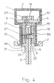
- 1 denotes a section of a rail hollow profile, which - as in FIG. 4 indicated - can be mounted in a ceiling 2 of a building and has a length corresponding to a length of a glass pane 3 to be clamped, here a laminated safety glass, which is shaped as a smoke skirt.
- the rail hollow profile has two parallel legs 4, 5, which define an open side 6 at the bottom and transition into an enlarged head section 7 at the top. The two legs extend with a mutual clearance parallel to each other. They go up into the extended head section with lateral horizontal cheeks 8 and 9.
- clamping pieces For storage of partially insertable between the legs 4, 5 of the rail hollow profile glass 3, this is in its upper, not designated Edge area clamped in clamping pieces, one of which is designated 10.
- the clamping pieces are shorter in the longitudinal direction than the glass sheet 3, which can be held by a plurality of such clamping pieces in a longer rail hollow section section.
- the clamping pieces are to be inserted into a clamping piece receiving space 11 of the rail hollow profile from below, as in FIG. 4 shown.
- clamping piece 10 is described in more detail:
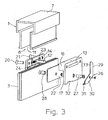
- clamping profile 15 which, with the exception of a laterally projecting head 16 has a flat wall portion 17, and a clamping plate 18, which covers the flat wall portion and the head 16 of the clamping profile laterally, leaving a bottom open clamping space 19, which is suitable to receive the edge portion of the glass sheet 3, see in particular Figures 3 and 4 ,
- Slits 13, 14 are formed, which extend in the longitudinal direction of the head piece according to the main direction of the rail hollow profile and through which the latch 12 'can pass, if it is not retracted within the slots 13, 14.
- the clamping profile 15 and the clamping plate 18 can be firmly held together with the inclusion of the glass sheet 3 by means of countersunk screws 20, 21 or compressed.
- a peripheral portion protective elastic pad 22 for example made of rubber, see FIG. 4 ,
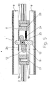
- the provided for supporting the clamping piece 10 in the rail hollow section 1 bolt 12 'and 12 is pivotally mounted with a cylindrical pin 23 as a vertical axis of rotation in the head 16 of the clamping profile 15, see in particular FIG. 4 , He is under the bias of a likewise housed in the head 16 tension spring 24, which according to FIG. 5 at a shoulder 25 of the bolt 12 'engages and the latch 12' seeks to pivot in the closed position.
- a lever plate 26 is arranged on the outside of the flat wall portion 17 of the clamping profile 15, which is approximately centered around a pin 27, i. a horizontal pivot axis is pivotable.
- the bolt 27 extends through the flat wall portion 17, the glass sheet 3 and the clamping plate 18 therethrough.
- the unspecified hole in the glass pane, through which the bolt 27 extends from steel, is protected by a sleeve 28 made of plastic or rubber.
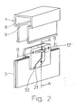
- the shape of the knee-shaped lever plate 26 is best from the Figures 1 - 3 out.
- the lever plate has an upper lever arm 29 which coincides with the Bar 12 and 12 'cooperates, and a lower lever arm 30 which may rest against the clamping profile 15 below, see in particular FIG. 2 ,
- an actuating surface 31 is angled from the lower lever arm.
- the actuating surface 31 after lifting out of the gap continue to operate directly without tools, which also applies to the pivoting back to the gap in the clockwise direction.
- the latch and the lever plate have the following functions:
- the lever plate is first levered by a tool from the gap and then manually pivoted counterclockwise, whereby its edge 33, the latch 12 'entrains and pivots in the closed position.
- the edge 33 slides off the latch, which is then pressed laterally by the tension spring 24 against the upper lever arm 29 of the lever plate 26, so that this position is stable when the lever plate is released.
- the clamping piece 10 with the glass sheet 3 can be easily inserted into the clamping piece receiving space 11.
- the latch 12 is first released so that it can swing out of the slots 13 and 14 and the edge 33 of the lever plate 26 can follow until it reaches the open position in which it rests stable on the horizontal cheeks 8 and 9.
Landscapes
- Engineering & Computer Science (AREA)
- Architecture (AREA)
- Physics & Mathematics (AREA)
- Electromagnetism (AREA)
- Civil Engineering (AREA)
- Structural Engineering (AREA)
- Mutual Connection Of Rods And Tubes (AREA)
- Securing Of Glass Panes Or The Like (AREA)
- Curtains And Furnishings For Windows Or Doors (AREA)
- Building Environments (AREA)
Claims (11)
- Structure de profilé de fixation au plafond pour des objets plats, en particulier pour des panneaux de verre (3) suspendus pour former des pare-fumée, comprenant un profilé creux formant rail (1) qui peut être attaché à un plafond et au moins un élément de pincement (10), le profilé creux formant rail (1) présentant intérieurement au moins une joue (8) sensiblement horizontale d'où part une première branche (4) rabattue verticalement vers le bas, le profilé creux formant rail (1) comprenant, parallèlement à la première branche (4) et à une distance de dégagement de celle-ci, une seconde branche (5) sensiblement verticale (5) qui délimite avec la première branche un espace (11) de logement de l'élément de pincement présentant un côté inférieur ouvert (6) dans lequel peut être inséré ledit au moins un élément de pincement (10) qui est éventuellement approprié pour pincer une région de bord de l'objet plat, l'élément de pincement présentant un verrou (12, 12') capable de pivoter autour d'un axe vertical (23) et un élément d'actionnement (26) du verrou (12, 12') qui peut être actionné au niveau du côté ouvert (6) de l'espace (11) de logement de l'élément de pincement, et le verrou ainsi que l'élément d'actionnement étant constitués et disposés de telle sorte que, dans une position d'ouverture, le verrou (12) s'étend seulement entre les branches (4, 5) ou dans un segment de tête (7) du profilé creux forant rail (1) qui est élargi au-dessus des branches, à côté de la joue (8), tandis que, dans une position de fermeture, il prend cependant appui sur la joue (8), caractérisée en ce que le verrou (12') est précontraint dans la position de fermeture par un ressort (24), en ce que l'élément d'actionnement (26) est constitué par un levier à deux bras qui peut pivoter autour d'un axe horizontal (27), le long d'un côté longitudinal (17) de l'élément de pincement, en ce qu'un bras de levier supérieur (29) est adjacent au verrou (12') de telle sorte que ce dernier peut être amené par pivotement dans la position d'ouverture par pivotement du levier, et en ce qu'un bras de levier inférieur (30) peut être actionné manuellement au niveau du côté ouvert (16) du profilé creux formant rail.
- Structure de profilé de fixation au plafond selon la revendication 1, caractérisée en ce que l'élément d'actionnement (26) comprend une plaque de tôle levier de forme coudée, qui est constituée et disposée de telle sorte que, dans la position de fermeture ainsi que lors du pivotement en position d'ouverture, le verrou (12 ou 12') est adjacent à une arête (33) du bras de levier supérieur (29) et que, lorsque la position d'ouverture est atteinte, il s'écarte de l'arête (33) et est pressé contre un côté longitudinal plat du bras de levier supérieur (29), position d'ouverture d'où le bras de levier supérieur (29) revient brusquement en position adjacente à l'arête (33) du verrou (12, 12') lors du pivotement en position de fermeture.
- Structure de profilé de fixation au plafond selon la revendication 2, caractérisée en ce que, du bras de levier inférieur (30) part une surface d'actionnement (31) rabattue latéralement de telle sorte que, dans la position de fermeture du verrou, la surface d'actionnement est adjacente à un côté inférieur de l'élément de pincement (10).
- Structure de profile de fixation au plafond selon la revendication 3, caractérisée en ce que, le long du côté inférieur de l'élément de pincement (10), est formée une fente (32) au niveau de laquelle la surface d'actionnement (31) peut être tirée vers le bas pour l'actionnement en position d'ouverture.
- Structure de profilé de fixation au plafond selon l'une des revendications précédentes, caractérisée en ce que l'élément de pincement (10) comportant un profilé de pincement (15) et une plaque de pincement (18) est assemblé le long d'un plan de pincement vertical de telle sorte que ces éléments délimitent un espace de pincement (19) le long de ses côtés longitudinaux et que le verrou (12 ou 12') est monté à l'intérieur d'une tête (16) du profilé de pincement (15) qui présente latéralement une première fente horizontale (13) à travers laquelle le verrou (12') passe dans la position de fermeture.
- Structure de profilé de fixation au plafond selon la revendication 5, caractérisée en ce que la plaque de pincement (18) est dotée, sur le côté opposé à la première fente (13) prévue dans la tête du profilé de pincement (15), d'une seconde fente horizontale correspondante (14) à travers laquelle le verrou (12') passe dans la position de fermeture.
- Structure de profilé de fixation au plafond selon l'une des revendications précédentes, caractérisée en ce qu'à peu près en son milieu, la plaque de tôle levier (26) est tourillonnée sur une vis (27) pour tourner autour de l'axe de rotation horizontal, et en ce que la vis (27) traverse des perçages mutuellement opposés du profilé de pincement (15) et de la plaque de pincement (18), ainsi que l'objet pincé entre ces éléments.
- Structure de profilé de fixation au plafond selon l'une des revendications précédentes, caractérisée en ce que le profilé creux formant rail (1) présente intérieurement deux joues horizontales (8, 9) situées à une distance de dégagement l'une de l'autre et d'où partent les première et seconde branches (4, 5) qui sont rabattues verticalement vers le bas en conservant la distance de dégagement, et en ce que le verrou (12') est constitué et disposé de telle sorte que, dans la position de fermeture, il prend appui sur les deux joues (8, 9).
- Structure de profilé de fixation au plafond selon l'une des revendications précédentes, caractérisée en ce que le profilé creux formant rail (1) est constitué en une seule pièce à peu près en forme de Ω.
- Structure de profilé de fixation au plafond selon l'une des revendications précédentes, caractérisée en ce que le profilé creux formant rail (1) est un profilé d'aluminium filé à la presse.
- Structure de profilé de fixation au plafond selon l'une des revendications précédentes, caractérisée en ce que l'élément de pincement (10) s'étend seulement sur un segment de la longueur du profilé creux formant rail (1).
Applications Claiming Priority (1)
| Application Number | Priority Date | Filing Date | Title |
|---|---|---|---|
| DE202006015058U DE202006015058U1 (de) | 2006-09-29 | 2006-09-29 | Deckenbefestigungsprofilanordnung für flächige Objekte, insbesondere vertikal aufgehängte Glasscheiben als Rauchschürzen |
Publications (2)
| Publication Number | Publication Date |
|---|---|
| EP1905916A1 EP1905916A1 (fr) | 2008-04-02 |
| EP1905916B1 true EP1905916B1 (fr) | 2011-06-15 |
Family
ID=37545558
Family Applications (1)
| Application Number | Title | Priority Date | Filing Date |
|---|---|---|---|
| EP06024354A Not-in-force EP1905916B1 (fr) | 2006-09-29 | 2006-11-24 | Dispositif de fixation d'objets plats au plafond, particulièrement de feuilles de verre comme protection contre la fumée |
Country Status (4)
| Country | Link |
|---|---|
| EP (1) | EP1905916B1 (fr) |
| AT (1) | ATE513093T1 (fr) |
| DE (1) | DE202006015058U1 (fr) |
| ES (1) | ES2363785T3 (fr) |
Cited By (1)
| Publication number | Priority date | Publication date | Assignee | Title |
|---|---|---|---|---|
| TWI813495B (zh) * | 2022-11-07 | 2023-08-21 | 寰奇機電有限公司 | 可單片拆裝之防煙垂壁裝置 |
Families Citing this family (4)
| Publication number | Priority date | Publication date | Assignee | Title |
|---|---|---|---|---|
| IT1391041B1 (it) † | 2008-07-11 | 2011-10-27 | Gemino Srl | Trave con dispositivo d'illuminazione, di un sistema integrato di partizione d'interni con controsoffitti e pareti divisorie. |
| ITVI20120162A1 (it) * | 2012-07-06 | 2014-01-07 | Vetroin S R L | Sistema per la partizione di ambienti |
| WO2016172685A1 (fr) * | 2015-04-24 | 2016-10-27 | Worthington Armstrong Venture | Canal pour panneau de verre intérieur |
| GB2545789B (en) | 2015-11-02 | 2020-04-01 | Autex Industries Ltd | Panel fixing assembly |
Family Cites Families (3)
| Publication number | Priority date | Publication date | Assignee | Title |
|---|---|---|---|---|
| US3619960A (en) * | 1969-11-04 | 1971-11-16 | Walter W Thompson | Combination ceiling grid and partition receiver |
| AT332066B (de) * | 1971-06-01 | 1976-09-10 | Norema As | Anordnung bei herabhangender decke |
| DE2435301C2 (de) | 1974-07-23 | 1985-01-10 | Riloga-Werk Julius Schmidt, 5630 Remscheid | Tragschiene für Unterdecken |
-
2006
- 2006-09-29 DE DE202006015058U patent/DE202006015058U1/de not_active Expired - Lifetime
- 2006-11-24 AT AT06024354T patent/ATE513093T1/de active
- 2006-11-24 ES ES06024354T patent/ES2363785T3/es active Active
- 2006-11-24 EP EP06024354A patent/EP1905916B1/fr not_active Not-in-force
Cited By (1)
| Publication number | Priority date | Publication date | Assignee | Title |
|---|---|---|---|---|
| TWI813495B (zh) * | 2022-11-07 | 2023-08-21 | 寰奇機電有限公司 | 可單片拆裝之防煙垂壁裝置 |
Also Published As
| Publication number | Publication date |
|---|---|
| ATE513093T1 (de) | 2011-07-15 |
| ES2363785T3 (es) | 2011-08-16 |
| EP1905916A1 (fr) | 2008-04-02 |
| DE202006015058U1 (de) | 2006-11-30 |
Similar Documents
| Publication | Publication Date | Title |
|---|---|---|
| EP1833133B1 (fr) | Dispositif de montage pour un caniveau de câbles et caniveau de câbles | |
| DE202013101519U1 (de) | Duschtür-Baugruppe | |
| EP0862873A1 (fr) | Ferrure pour fixation | |
| AT511046B1 (de) | Rahmensystem eines partikelschutzgitters | |
| EP1905916B1 (fr) | Dispositif de fixation d'objets plats au plafond, particulièrement de feuilles de verre comme protection contre la fumée | |
| DE102013100922B4 (de) | Laufteil zum Führen eines Möbelteils in einer Führungsrichtung über eine Führungsschiene und Möbelbeschlag | |
| EP2407604A1 (fr) | Dispositif de connexion | |
| EP1662627B1 (fr) | Dispositif pour la fixation détachable d'un boîtier d'appareil à un rail profilé | |
| EP3564589B1 (fr) | Dispositif d'aération | |
| EP1134490B1 (fr) | Dispositif de montage pour luminaire encastré et luminaire correspondant | |
| DE19930949B4 (de) | Verriegelungsmechanismus für ortsveränderliche Wand | |
| EP1505705B1 (fr) | Dispositif de montage pour canalisation pour cable . | |
| DE10109098A1 (de) | Bandaufnahmevorrichtung zur Anbringung an einem Tür- oder Fensterflügel oder an einer Zarge | |
| DE10101722A1 (de) | Lamelle für Beschattungs- und/oder Lichtleiteinrichtungen für Gebäude | |
| DE20112435U1 (de) | Punkthalter für Verbundsicherheitsglasplatte | |
| DE29617597U1 (de) | Verriegelungsvorrichtung für ein in einer Zarge bewegbares Tür- oder Torblatt | |
| DE102020000182A1 (de) | Zusatzverriegelung mit Spaltlüftungsfunktion | |
| EP1777363B1 (fr) | Dispositif d'arrêt pour une porte d'un boîtier | |
| AT510643B1 (de) | Projektionswandbefestigungsvorrichtung | |
| DE2632711A1 (de) | Rolladensicherung | |
| DE10142470C1 (de) | Fehlbedienungssicherung für Treibstangenbeschläge | |
| EP3768929A1 (fr) | Joint de porte pourvu d'un élément de fixation | |
| WO2019161424A1 (fr) | Support de montage pour rails de guidage | |
| AT407334B (de) | Befestigungsbeschlag | |
| DE2707484C2 (fr) |
Legal Events
| Date | Code | Title | Description |
|---|---|---|---|
| PUAI | Public reference made under article 153(3) epc to a published international application that has entered the european phase |
Free format text: ORIGINAL CODE: 0009012 |
|
| AK | Designated contracting states |
Kind code of ref document: A1 Designated state(s): AT BE BG CH CY CZ DE DK EE ES FI FR GB GR HU IE IS IT LI LT LU LV MC NL PL PT RO SE SI SK TR |
|
| AX | Request for extension of the european patent |
Extension state: AL BA HR MK YU |
|
| 17P | Request for examination filed |
Effective date: 20081002 |
|
| 17Q | First examination report despatched |
Effective date: 20081030 |
|
| AKX | Designation fees paid |
Designated state(s): AT BE BG CH CY CZ DE DK EE ES FI FR GB GR HU IE IS IT LI LT LU LV MC NL PL PT RO SE SI SK TR |
|
| GRAP | Despatch of communication of intention to grant a patent |
Free format text: ORIGINAL CODE: EPIDOSNIGR1 |
|
| GRAS | Grant fee paid |
Free format text: ORIGINAL CODE: EPIDOSNIGR3 |
|
| GRAA | (expected) grant |
Free format text: ORIGINAL CODE: 0009210 |
|
| AK | Designated contracting states |
Kind code of ref document: B1 Designated state(s): AT BE BG CH CY CZ DE DK EE ES FI FR GB GR HU IE IS IT LI LT LU LV MC NL PL PT RO SE SI SK TR |
|
| REG | Reference to a national code |
Ref country code: GB Ref legal event code: FG4D Free format text: NOT ENGLISH Ref country code: CH Ref legal event code: EP |
|
| REG | Reference to a national code |
Ref country code: CH Ref legal event code: NV Representative=s name: BOHEST AG |
|
| REG | Reference to a national code |
Ref country code: IE Ref legal event code: FG4D Free format text: LANGUAGE OF EP DOCUMENT: GERMAN |
|
| REG | Reference to a national code |
Ref country code: DE Ref legal event code: R096 Ref document number: 502006009650 Country of ref document: DE Effective date: 20110728 |
|
| REG | Reference to a national code |
Ref country code: ES Ref legal event code: FG2A Ref document number: 2363785 Country of ref document: ES Kind code of ref document: T3 Effective date: 20110816 |
|
| REG | Reference to a national code |
Ref country code: NL Ref legal event code: T3 |
|
| PG25 | Lapsed in a contracting state [announced via postgrant information from national office to epo] |
Ref country code: LT Free format text: LAPSE BECAUSE OF FAILURE TO SUBMIT A TRANSLATION OF THE DESCRIPTION OR TO PAY THE FEE WITHIN THE PRESCRIBED TIME-LIMIT Effective date: 20110615 Ref country code: SE Free format text: LAPSE BECAUSE OF FAILURE TO SUBMIT A TRANSLATION OF THE DESCRIPTION OR TO PAY THE FEE WITHIN THE PRESCRIBED TIME-LIMIT Effective date: 20110615 |
|
| PG25 | Lapsed in a contracting state [announced via postgrant information from national office to epo] |
Ref country code: SI Free format text: LAPSE BECAUSE OF FAILURE TO SUBMIT A TRANSLATION OF THE DESCRIPTION OR TO PAY THE FEE WITHIN THE PRESCRIBED TIME-LIMIT Effective date: 20110615 Ref country code: GR Free format text: LAPSE BECAUSE OF FAILURE TO SUBMIT A TRANSLATION OF THE DESCRIPTION OR TO PAY THE FEE WITHIN THE PRESCRIBED TIME-LIMIT Effective date: 20110916 Ref country code: FI Free format text: LAPSE BECAUSE OF FAILURE TO SUBMIT A TRANSLATION OF THE DESCRIPTION OR TO PAY THE FEE WITHIN THE PRESCRIBED TIME-LIMIT Effective date: 20110615 Ref country code: LV Free format text: LAPSE BECAUSE OF FAILURE TO SUBMIT A TRANSLATION OF THE DESCRIPTION OR TO PAY THE FEE WITHIN THE PRESCRIBED TIME-LIMIT Effective date: 20110615 Ref country code: CY Free format text: LAPSE BECAUSE OF FAILURE TO SUBMIT A TRANSLATION OF THE DESCRIPTION OR TO PAY THE FEE WITHIN THE PRESCRIBED TIME-LIMIT Effective date: 20110615 |
|
| REG | Reference to a national code |
Ref country code: IE Ref legal event code: FD4D |
|
| PG25 | Lapsed in a contracting state [announced via postgrant information from national office to epo] |
Ref country code: CZ Free format text: LAPSE BECAUSE OF FAILURE TO SUBMIT A TRANSLATION OF THE DESCRIPTION OR TO PAY THE FEE WITHIN THE PRESCRIBED TIME-LIMIT Effective date: 20110615 Ref country code: IS Free format text: LAPSE BECAUSE OF FAILURE TO SUBMIT A TRANSLATION OF THE DESCRIPTION OR TO PAY THE FEE WITHIN THE PRESCRIBED TIME-LIMIT Effective date: 20111015 Ref country code: EE Free format text: LAPSE BECAUSE OF FAILURE TO SUBMIT A TRANSLATION OF THE DESCRIPTION OR TO PAY THE FEE WITHIN THE PRESCRIBED TIME-LIMIT Effective date: 20110615 Ref country code: IE Free format text: LAPSE BECAUSE OF FAILURE TO SUBMIT A TRANSLATION OF THE DESCRIPTION OR TO PAY THE FEE WITHIN THE PRESCRIBED TIME-LIMIT Effective date: 20110615 Ref country code: PT Free format text: LAPSE BECAUSE OF FAILURE TO SUBMIT A TRANSLATION OF THE DESCRIPTION OR TO PAY THE FEE WITHIN THE PRESCRIBED TIME-LIMIT Effective date: 20111017 |
|
| PGFP | Annual fee paid to national office [announced via postgrant information from national office to epo] |
Ref country code: FR Payment date: 20111130 Year of fee payment: 6 Ref country code: ES Payment date: 20111124 Year of fee payment: 6 |
|
| PG25 | Lapsed in a contracting state [announced via postgrant information from national office to epo] |
Ref country code: RO Free format text: LAPSE BECAUSE OF FAILURE TO SUBMIT A TRANSLATION OF THE DESCRIPTION OR TO PAY THE FEE WITHIN THE PRESCRIBED TIME-LIMIT Effective date: 20110615 Ref country code: SK Free format text: LAPSE BECAUSE OF FAILURE TO SUBMIT A TRANSLATION OF THE DESCRIPTION OR TO PAY THE FEE WITHIN THE PRESCRIBED TIME-LIMIT Effective date: 20110615 Ref country code: PL Free format text: LAPSE BECAUSE OF FAILURE TO SUBMIT A TRANSLATION OF THE DESCRIPTION OR TO PAY THE FEE WITHIN THE PRESCRIBED TIME-LIMIT Effective date: 20110615 |
|
| PLBE | No opposition filed within time limit |
Free format text: ORIGINAL CODE: 0009261 |
|
| STAA | Information on the status of an ep patent application or granted ep patent |
Free format text: STATUS: NO OPPOSITION FILED WITHIN TIME LIMIT |
|
| 26N | No opposition filed |
Effective date: 20120316 |
|
| PG25 | Lapsed in a contracting state [announced via postgrant information from national office to epo] |
Ref country code: MC Free format text: LAPSE BECAUSE OF NON-PAYMENT OF DUE FEES Effective date: 20111130 Ref country code: DK Free format text: LAPSE BECAUSE OF FAILURE TO SUBMIT A TRANSLATION OF THE DESCRIPTION OR TO PAY THE FEE WITHIN THE PRESCRIBED TIME-LIMIT Effective date: 20110615 |
|
| REG | Reference to a national code |
Ref country code: DE Ref legal event code: R097 Ref document number: 502006009650 Country of ref document: DE Effective date: 20120316 |
|
| PG25 | Lapsed in a contracting state [announced via postgrant information from national office to epo] |
Ref country code: LU Free format text: LAPSE BECAUSE OF NON-PAYMENT OF DUE FEES Effective date: 20111124 |
|
| PG25 | Lapsed in a contracting state [announced via postgrant information from national office to epo] |
Ref country code: BG Free format text: LAPSE BECAUSE OF FAILURE TO SUBMIT A TRANSLATION OF THE DESCRIPTION OR TO PAY THE FEE WITHIN THE PRESCRIBED TIME-LIMIT Effective date: 20110915 |
|
| REG | Reference to a national code |
Ref country code: FR Ref legal event code: ST Effective date: 20130731 |
|
| PG25 | Lapsed in a contracting state [announced via postgrant information from national office to epo] |
Ref country code: IT Free format text: LAPSE BECAUSE OF NON-PAYMENT OF DUE FEES Effective date: 20121124 |
|
| PG25 | Lapsed in a contracting state [announced via postgrant information from national office to epo] |
Ref country code: TR Free format text: LAPSE BECAUSE OF FAILURE TO SUBMIT A TRANSLATION OF THE DESCRIPTION OR TO PAY THE FEE WITHIN THE PRESCRIBED TIME-LIMIT Effective date: 20110615 |
|
| PG25 | Lapsed in a contracting state [announced via postgrant information from national office to epo] |
Ref country code: HU Free format text: LAPSE BECAUSE OF FAILURE TO SUBMIT A TRANSLATION OF THE DESCRIPTION OR TO PAY THE FEE WITHIN THE PRESCRIBED TIME-LIMIT Effective date: 20110615 |
|
| PG25 | Lapsed in a contracting state [announced via postgrant information from national office to epo] |
Ref country code: FR Free format text: LAPSE BECAUSE OF NON-PAYMENT OF DUE FEES Effective date: 20121130 |
|
| REG | Reference to a national code |
Ref country code: ES Ref legal event code: FD2A Effective date: 20140527 |
|
| PG25 | Lapsed in a contracting state [announced via postgrant information from national office to epo] |
Ref country code: ES Free format text: LAPSE BECAUSE OF NON-PAYMENT OF DUE FEES Effective date: 20121125 |
|
| REG | Reference to a national code |
Ref country code: CH Ref legal event code: PCAR Free format text: NEW ADDRESS: HOLBEINSTRASSE 36-38, 4051 BASEL (CH) |
|
| PGFP | Annual fee paid to national office [announced via postgrant information from national office to epo] |
Ref country code: NL Payment date: 20151119 Year of fee payment: 10 Ref country code: BE Payment date: 20151126 Year of fee payment: 10 |
|
| PG25 | Lapsed in a contracting state [announced via postgrant information from national office to epo] |
Ref country code: BE Free format text: LAPSE BECAUSE OF NON-PAYMENT OF DUE FEES Effective date: 20161130 |
|
| REG | Reference to a national code |
Ref country code: NL Ref legal event code: MM Effective date: 20161201 |
|
| REG | Reference to a national code |
Ref country code: DE Ref legal event code: R082 Ref document number: 502006009650 Country of ref document: DE Representative=s name: KEIL & SCHAAFHAUSEN PATENTANWAELTE PARTGMBB, DE Ref country code: DE Ref legal event code: R082 Ref document number: 502006009650 Country of ref document: DE Representative=s name: KEIL & SCHAAFHAUSEN PATENT- UND RECHTSANWAELTE, DE |
|
| PG25 | Lapsed in a contracting state [announced via postgrant information from national office to epo] |
Ref country code: NL Free format text: LAPSE BECAUSE OF NON-PAYMENT OF DUE FEES Effective date: 20161201 |
|
| REG | Reference to a national code |
Ref country code: BE Ref legal event code: MM Effective date: 20161130 |
|
| PGFP | Annual fee paid to national office [announced via postgrant information from national office to epo] |
Ref country code: DE Payment date: 20181129 Year of fee payment: 13 Ref country code: AT Payment date: 20181120 Year of fee payment: 13 |
|
| PGFP | Annual fee paid to national office [announced via postgrant information from national office to epo] |
Ref country code: GB Payment date: 20181126 Year of fee payment: 13 Ref country code: CH Payment date: 20181126 Year of fee payment: 13 |
|
| REG | Reference to a national code |
Ref country code: DE Ref legal event code: R119 Ref document number: 502006009650 Country of ref document: DE |
|
| REG | Reference to a national code |
Ref country code: CH Ref legal event code: PL |
|
| PG25 | Lapsed in a contracting state [announced via postgrant information from national office to epo] |
Ref country code: CH Free format text: LAPSE BECAUSE OF NON-PAYMENT OF DUE FEES Effective date: 20191130 Ref country code: LI Free format text: LAPSE BECAUSE OF NON-PAYMENT OF DUE FEES Effective date: 20191130 |
|
| REG | Reference to a national code |
Ref country code: AT Ref legal event code: MM01 Ref document number: 513093 Country of ref document: AT Kind code of ref document: T Effective date: 20191124 |
|
| GBPC | Gb: european patent ceased through non-payment of renewal fee |
Effective date: 20191124 |
|
| PG25 | Lapsed in a contracting state [announced via postgrant information from national office to epo] |
Ref country code: DE Free format text: LAPSE BECAUSE OF NON-PAYMENT OF DUE FEES Effective date: 20200603 Ref country code: GB Free format text: LAPSE BECAUSE OF NON-PAYMENT OF DUE FEES Effective date: 20191124 |
|
| PG25 | Lapsed in a contracting state [announced via postgrant information from national office to epo] |
Ref country code: AT Free format text: LAPSE BECAUSE OF NON-PAYMENT OF DUE FEES Effective date: 20191124 |