EP1905932A2 - Porte coulissante - Google Patents
Porte coulissante Download PDFInfo
- Publication number
- EP1905932A2 EP1905932A2 EP07019098A EP07019098A EP1905932A2 EP 1905932 A2 EP1905932 A2 EP 1905932A2 EP 07019098 A EP07019098 A EP 07019098A EP 07019098 A EP07019098 A EP 07019098A EP 1905932 A2 EP1905932 A2 EP 1905932A2
- Authority
- EP
- European Patent Office
- Prior art keywords
- sliding door
- fastening
- drive unit
- motor vehicle
- drive
- Prior art date
- Legal status (The legal status is an assumption and is not a legal conclusion. Google has not performed a legal analysis and makes no representation as to the accuracy of the status listed.)
- Granted
Links
Images


Classifications
-
- E—FIXED CONSTRUCTIONS
- E05—LOCKS; KEYS; WINDOW OR DOOR FITTINGS; SAFES
- E05F—DEVICES FOR MOVING WINGS INTO OPEN OR CLOSED POSITION; CHECKS FOR WINGS; WING FITTINGS NOT OTHERWISE PROVIDED FOR, CONCERNED WITH THE FUNCTIONING OF THE WING
- E05F15/00—Power-operated mechanisms for wings
- E05F15/60—Power-operated mechanisms for wings using electrical actuators
- E05F15/603—Power-operated mechanisms for wings using electrical actuators using rotary electromotors
- E05F15/632—Power-operated mechanisms for wings using electrical actuators using rotary electromotors for horizontally-sliding wings
- E05F15/643—Power-operated mechanisms for wings using electrical actuators using rotary electromotors for horizontally-sliding wings operated by flexible elongated pulling elements, e.g. belts, chains or cables
- E05F15/646—Power-operated mechanisms for wings using electrical actuators using rotary electromotors for horizontally-sliding wings operated by flexible elongated pulling elements, e.g. belts, chains or cables allowing or involving a secondary movement of the wing, e.g. rotational or transversal
-
- E—FIXED CONSTRUCTIONS
- E05—LOCKS; KEYS; WINDOW OR DOOR FITTINGS; SAFES
- E05Y—INDEXING SCHEME ASSOCIATED WITH SUBCLASSES E05D AND E05F, RELATING TO CONSTRUCTION ELEMENTS, ELECTRIC CONTROL, POWER SUPPLY, POWER SIGNAL OR TRANSMISSION, USER INTERFACES, MOUNTING OR COUPLING, DETAILS, ACCESSORIES, AUXILIARY OPERATIONS NOT OTHERWISE PROVIDED FOR, APPLICATION THEREOF
- E05Y2201/00—Constructional elements; Accessories therefor
- E05Y2201/20—Brakes; Disengaging means; Holders; Stops; Valves; Accessories therefor
- E05Y2201/218—Holders
- E05Y2201/22—Locks
-
- E—FIXED CONSTRUCTIONS
- E05—LOCKS; KEYS; WINDOW OR DOOR FITTINGS; SAFES
- E05Y—INDEXING SCHEME ASSOCIATED WITH SUBCLASSES E05D AND E05F, RELATING TO CONSTRUCTION ELEMENTS, ELECTRIC CONTROL, POWER SUPPLY, POWER SIGNAL OR TRANSMISSION, USER INTERFACES, MOUNTING OR COUPLING, DETAILS, ACCESSORIES, AUXILIARY OPERATIONS NOT OTHERWISE PROVIDED FOR, APPLICATION THEREOF
- E05Y2201/00—Constructional elements; Accessories therefor
- E05Y2201/60—Suspension or transmission members; Accessories therefor
- E05Y2201/622—Suspension or transmission members elements
- E05Y2201/71—Toothed gearing
- E05Y2201/72—Planetary gearing
-
- E—FIXED CONSTRUCTIONS
- E05—LOCKS; KEYS; WINDOW OR DOOR FITTINGS; SAFES
- E05Y—INDEXING SCHEME ASSOCIATED WITH SUBCLASSES E05D AND E05F, RELATING TO CONSTRUCTION ELEMENTS, ELECTRIC CONTROL, POWER SUPPLY, POWER SIGNAL OR TRANSMISSION, USER INTERFACES, MOUNTING OR COUPLING, DETAILS, ACCESSORIES, AUXILIARY OPERATIONS NOT OTHERWISE PROVIDED FOR, APPLICATION THEREOF
- E05Y2400/00—Electronic control; Electrical power; Power supply; Power or signal transmission; User interfaces
- E05Y2400/10—Electronic control
- E05Y2400/30—Electronic control of motors
- E05Y2400/3013—Electronic control of motors during manual wing operation
-
- E—FIXED CONSTRUCTIONS
- E05—LOCKS; KEYS; WINDOW OR DOOR FITTINGS; SAFES
- E05Y—INDEXING SCHEME ASSOCIATED WITH SUBCLASSES E05D AND E05F, RELATING TO CONSTRUCTION ELEMENTS, ELECTRIC CONTROL, POWER SUPPLY, POWER SIGNAL OR TRANSMISSION, USER INTERFACES, MOUNTING OR COUPLING, DETAILS, ACCESSORIES, AUXILIARY OPERATIONS NOT OTHERWISE PROVIDED FOR, APPLICATION THEREOF
- E05Y2900/00—Application of doors, windows, wings or fittings thereof
- E05Y2900/50—Application of doors, windows, wings or fittings thereof for vehicles
- E05Y2900/53—Type of wing
- E05Y2900/531—Doors
Definitions
- the invention relates to a sliding door for a motor vehicle, with at least one drive unit.
- sliding doors are known from practice and are used, inter alia, in the DE 10 2004 021 555 A1 described.
- a guide device which is composed essentially of the drive unit and a guideway.
- the sliding door may be guided by means of rollers which are fastened to the sliding door.
- the drive unit generally has an electrically operating drive motor, which operates via an optionally interposed gear on a cable drum, which receives attached to the sliding door ropes.
- the attachment of the drive unit is usually inside the body of the vehicle to protect it from the weather. Only the one or more side or generally flexible drive means are guided through the body to the outside and anchored there with the sliding door.
- the drive motor the prior art according to the DE 298 21 465 U1 for example, before it is attached to a pivoting arm of a running in a central guide rail car.
- the flexible drive means passes through said pivot arm through to a sprocket.
- the state of the art can not convincingly convince, in particular as regards the attachment of the drive unit to the body of the motor vehicle. Because the assembly is expensive. In addition, sealing problems can occur. Here, the invention aims to provide a total remedy.
- the invention is based on the technical problem of further developing a sliding door of the embodiment described above so that the assembly is simplified and a reliable operation is ensured.
- a generic sliding door is in the context of the invention characterized in that the drive unit is wholly or partly fixed by means of at least one body opening by means of a comprehensive fastening means on the vehicle.
- the drive unit has a drive motor, optionally a transmission and a deflection device for a flexible drive means, such as a rope.
- the drive motor and the optional gear and the deflection advantageously together take a compact installation module.
- This compact built-in module can now be anchored to the vehicle only with the help of one (single) fastener. Accordingly, no further fasteners are required except for the thus singular fastening means.
- the installation of the module in question requires only the attachment of the fastener on the vehicle or in the associated body opening.
- the drive unit already finds its position for a perfect function.
- the fastening means not only defines the drive unit or the previously described compact installation module in the body opening, but at the same time seals the body opening.
- the fastener thus takes on a dual function. On the one hand, it serves to fix the drive unit or the compact installation module to the body of the motor vehicle. On the other hand, the obligatory body opening is sealed at the same time in this attachment or assembly.
- the fastener may have a hollow bore through which the flexible drive means is guided.
- this hollow bore regularly provides a grommet. Because the hollow bore is closed by the aforementioned and preferably tapered grommet with passage opening for the drive means.
- This two-part fastening means is essentially composed of a fastening pin arranged on the drive unit and a fastening nut cooperating with the fastening pin.
- the fastening pin passes through the body opening, while the fastening nut defines the vehicle body opening by cross-fixing pins on the motor vehicle.
- the mounting pin is advantageously connected to a housing. If the housing is made of plastic, a one-piece connection is recommended, that is, that the mounting pin and the housing are integrally formed.
- the housing may not be limited to the baffle housing, that is, the housing which encloses the baffle for the flexible drive means. In principle, however, the mounting pin can also be connected in one piece to a drive motor housing, a transmission housing or the like.
- the ratchet teeth and the Rasteinformungen leave only a combination of mounting pin and mounting nut in a direction of rotation, the mounting direction, and act against this mounting direction as a barrier, so that the fastening nut can not accidentally come off the mounting pin. This contributes to functional reliability.
- the grommet is advantageously equipped with a fastening pin on the head side superior clamping edge.
- This clamping edge engages in a rule in a clamping recess in the fastening nut.
- the grommet is fixed, namely, when the fastening nut is screwed onto the mounting pin and engages in this process, the clamping edge in the clamping recess. Since the fastening nut can not be solved automatically by the mounting pin, the assembly not only leads to a perfect fit of the drive unit on the motor vehicle, but at the same time that a defined and permanent seal using the fixed grommet is achieved.
- the fastening nut can advantageously be made of plastic - such as the mounting pin. As a result, the production costs can be kept low, at the same time a flawless operation is given.
- a sliding door for a motor vehicle is presented, which is characterized by a particularly simple structural design or a functionally appropriate attachment of the drive unit.
- the drive unit can be set to save space and as it were only by a single assembly step on the body of the vehicle. For this it is only necessary that the drive unit or the compact installation module is anchored to the body opening with the aid of the fastening means. In this as it were single assembly step is also taken care of a reliable seal the body opening.
- the main benefits are the main benefits.
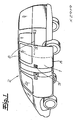
- a sliding door 1 for a motor vehicle 2 is shown.
- the sliding door 1 can be transferred from a closed position indicated by dashed lines in an open position, as indicated. This can be done manually or by motor. To do this, a motor vehicle door lock 3 assigned to the sliding door 1 must first be unlocked and opened.
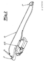
- the sliding door 1 is moved into the open and the closed position with the aid of a drive unit 4, 5, 6, 7 to be recognized in FIG. 2.
- the drive unit 4, 5, 6, 7 has an electromotive drive motor 4, a transmission 5 following the drive motor 4 as well as ropes 6 and finally deflection devices 7 for the two ropes 6.
- the sliding door 1 is connected to the two cables 6, the respective length of which is changed by means of the drive motor 4 including the transmission 5 with the interposition of a cable drum to be recognized in FIG.
- the sliding door 1 is reciprocated along a guideway 8 indicated only in FIG.
- 8 guided rollers are attached to the sliding door 1 in the guideway.
- This guide device 4, 5, 6, 7, 8 is of course also then Use, for example, if the drive motor 4 should have failed and the sliding door 1 manually (emergency) must be pressed.
- FIG. 1 Details of the drive unit 4, 5 are shown in FIG.
- a clutch actuator 5a can be seen which has a translationally displaceable boom 5b, which in turn acts on a clutch lever 5c of the gearbox 5.
- the transmission 5 is a planetary gear.
- the drive motor 4 When the drive motor 4 is energized, its rotation is transmitted to a drive worm 9 provided on the output side of the drive motor 4, which drives the transmission 5 and thus the cable drum already provided on the output side of the transmission 5. Since the planet carrier of the transmission 5 is blocked by a locking lever 10, the rotational movement introduced via the drive motor 4 is transmitted to a ring gear of the planetary gear, that in turn is connected to the cable drum. As a result, the respective cable 6 is wound up and unwound, so that the sliding door 2 performs the mentioned movement in its closed position or open position.
- a sensor not shown, is arranged, with the aid of the speed and direction of rotation of the cable drum can be detected and evaluated.
- the locking lever 10 With the aid of the clutch actuator 5a, the locking lever 10 can be brought into engagement and out of engagement with the planet carrier of the transmission 5.
- the cable drum and with it the sliding door 1 by means of the drive motor 4 is reciprocated. If, however, the locking lever 10 is not in engagement with the planet, so the sliding door 1 can be moved manually. Because in this case, the rotatably connected to the cable drum ring gear rolls over the planet gears, so that the planet carrier is moved with.
- the sun gear connected to the drive motor 4, like the drive motor 4, remains unaffected by this movement initiation. In this way, the manual movement of the sliding door 2 is not unnecessarily difficult.
- the locking lever 10 is associated with a spring, not shown, which loads the locking lever 10 in its "uncoupled” position.
- the locking lever 10 is acted upon by the coupling actuator 5a via the boom 5b or the clutch lever 5c. So you will always proceed when the sliding door 1 is to be moved by motor with the help of the drive motor 4.
- the spring ensures the "uncoupled” position of the locking lever 10, so that the sliding door 1 can move manually with reduced force, because the drive motor 4 does not need to be moved.
- the fastening means 12, 13 not only ensures that the drive unit 4, 5, 6, 7 is fixed to the body or the motor vehicle 2, but at the same time for the fact that the body opening 11 is sealed.
- two seals 14, 15 are provided in the core, namely a sealing ring 14 formed as a seal 14 and a tapered sealing grommet 15th
- the fastening means 12, 13 is equipped with a hollow bore 16 through which the flexible drive means or cable 6 is passed.
- the hollow bore 16 in question is closed by means of the sealing grommet 15 tapering in the direction of the installation module 4, 5, 7. It is understood that the grommet 15 with a in Figs. 5 and 6a, 6b not expressly to recognizing bushing opening for the drive means 6 is equipped.
- the passage opening is adapted from its inner diameter to the outer diameter of the flexible drive means or rope 6 and sealingly conforms to the outer periphery of the drive means 6.
- the fastening means 12, 13 is formed in two parts. In fact, there is a on the drive unit 4, 5, 6, 7 or, the compact mounting module 4, 5, 7 arranged mounting pin 12 which cooperates with a fastening nut 13.
- the fastening pin 12 passes through the body opening 11 and is arranged on a housing 17.
- This housing 17 is not limited to the Umlenk Anlagensgephaseuse 17, so the housing 17, which receives in its interior the deflection device 7 for the cable or flexible drive means 6.
- the Umlenk stressessgephase 17 and the mounting pins 12 are integrally formed of plastic. This is not mandatory.
- the fastening nut 13 is advantageously made of plastic. 6a and 6b it can be seen that the mounting pin 12 is equipped with outer peripheral side Rasteinformmaschine 18, in which in the fastening nut 13 provided inner peripheral locking teeth 19 engage in the union of mounting pin 12 and mounting nut 13.
- the arrangement of on the one hand the Rasteinformungen 18 on the mounting pin 12 and on the other hand, the locking teeth 19 in the mounting nut 13 is selected so that the fastening nut 13 can be screwed only in one direction of rotation on the mounting pin 12 and secured against reverse rotation. For movements of the fastening nut 13 against the drawn in Fig. 6a assembly direction of rotation are not allowed, because in this case the ratchet teeth 19 can not overlap the locking notices 18 acting as barbs.
- the grommet 15 has a clamping edge 15a projecting over or over the fastening pin 12 on the head side.
- This clamping edge 15a is received in a clamping recess 13a in the fastening nut 13 for fixing the grommet 15 when screwed onto the mounting pin 12 fastening nut 13.
- a disc 20 made of plastic which is arranged between the fastening nut 13 and an edge of the body opening 11. This plastic disc 20 ensures that the fastening nut 13 can be properly fixed on the mounting pin 12, namely by the friction between a head of the fastening nut 13 and the edge of the body opening 11 is reduced.
- said head of the fastening nut 13 would slide without the disc 20 made of plastic directly on the usually made of steel body or the motor vehicle 2, which is unfavorable in terms of friction and possibly could lead to damage and thus rust. That is, the disc 20 made of plastic not only ensures defined and favorable friction conditions between the mounting nut 13 and the edge of the mounting hole 11, but at the same time prevents any corrosion at this point.
Landscapes
- Power-Operated Mechanisms For Wings (AREA)
Applications Claiming Priority (1)
| Application Number | Priority Date | Filing Date | Title |
|---|---|---|---|
| DE202006015068U DE202006015068U1 (de) | 2006-09-30 | 2006-09-30 | Schiebetür |
Publications (3)
| Publication Number | Publication Date |
|---|---|
| EP1905932A2 true EP1905932A2 (fr) | 2008-04-02 |
| EP1905932A3 EP1905932A3 (fr) | 2009-05-13 |
| EP1905932B1 EP1905932B1 (fr) | 2012-08-29 |
Family
ID=38828566
Family Applications (1)
| Application Number | Title | Priority Date | Filing Date |
|---|---|---|---|
| EP07019098A Active EP1905932B1 (fr) | 2006-09-30 | 2007-09-28 | Porte coulissante |
Country Status (2)
| Country | Link |
|---|---|
| EP (1) | EP1905932B1 (fr) |
| DE (1) | DE202006015068U1 (fr) |
Families Citing this family (2)
| Publication number | Priority date | Publication date | Assignee | Title |
|---|---|---|---|---|
| DE202017100346U1 (de) | 2017-02-06 | 2017-02-10 | Kiekert Ag | Vorrichtung zur Einführung eines Führungsseils |
| DE102019131053A1 (de) * | 2019-11-18 | 2021-05-20 | Kiekert Aktiengesellschaft | Kraftfahrzeugtürantrieb, insbesondere Kraftfahrzeugschiebetürantrieb |
Citations (2)
| Publication number | Priority date | Publication date | Assignee | Title |
|---|---|---|---|---|
| DE29821465U1 (de) | 1998-11-27 | 1999-12-23 | Lunke Ventra Automotive Gmbh | Schiebetür mit Mittelschienenführung |
| DE102004021555A1 (de) | 2004-05-03 | 2005-12-01 | Daimlerchrysler Ag | Schiebetür für ein Kraftfahrzeug |
Family Cites Families (4)
| Publication number | Priority date | Publication date | Assignee | Title |
|---|---|---|---|---|
| US5319881A (en) * | 1993-01-25 | 1994-06-14 | General Motors Corporation | Sliding door closed loop cable closure system with balanced cable length and varying diameter pulleys |
| US6408572B1 (en) * | 1998-06-03 | 2002-06-25 | Mitsuba Corporation | Driving gear |
| US7243461B2 (en) * | 2003-03-19 | 2007-07-17 | Rogers Jr Lloyd W | Hinge mechanism for a sliding door |
| DE10350739A1 (de) * | 2003-10-30 | 2005-06-02 | Valeo Sicherheitssysteme Gmbh | Vorrichtung zum Verschieben der Schiebetür eines Kraftfahrzeuges |
-
2006
- 2006-09-30 DE DE202006015068U patent/DE202006015068U1/de not_active Expired - Lifetime
-
2007
- 2007-09-28 EP EP07019098A patent/EP1905932B1/fr active Active
Patent Citations (2)
| Publication number | Priority date | Publication date | Assignee | Title |
|---|---|---|---|---|
| DE29821465U1 (de) | 1998-11-27 | 1999-12-23 | Lunke Ventra Automotive Gmbh | Schiebetür mit Mittelschienenführung |
| DE102004021555A1 (de) | 2004-05-03 | 2005-12-01 | Daimlerchrysler Ag | Schiebetür für ein Kraftfahrzeug |
Also Published As
| Publication number | Publication date |
|---|---|
| EP1905932B1 (fr) | 2012-08-29 |
| EP1905932A3 (fr) | 2009-05-13 |
| DE202006015068U1 (de) | 2008-02-21 |
Similar Documents
| Publication | Publication Date | Title |
|---|---|---|
| EP3899179B1 (fr) | Dispositif d'installation pour une porte de véhicule automobile | |
| EP3347556B1 (fr) | Entraînement de porte coulissante de véhicule automobile | |
| EP0708218B1 (fr) | Dispositif de mise en oeuvre du processus de fermeture et d'ouverture d'une fenêtre basculante | |
| DE2758874A1 (de) | Verbesserungen an mit drahtzug arbeitenden fensterhebern, insbesondere fuer kraftfahrzeuge | |
| DE4401413C2 (de) | Fahrzeugtür | |
| EP2857616B1 (fr) | Agencement d'entraînement pour une serrure de véhicule automobile | |
| DE102019115304A1 (de) | Aufstellvorrichtung für ein Kraftfahrzeugtürelement | |
| EP1905629A2 (fr) | Porte coulissante | |
| EP2146032B1 (fr) | Dispositif destiné à ouvrir et/ou fermer ainsi qu'à verrouiller un état fermé d'un dispositif de fermeture destiné à fermer une ouverture de salle ainsi que dispositif de fermeture doté d'un tel dispositif | |
| EP1905932B1 (fr) | Porte coulissante | |
| EP1317594A1 (fr) | Systeme d'ouverture de porte destine notamment a des vehicules | |
| WO2023006144A1 (fr) | Dispositif de positionnement pour une portière de véhicule automobile | |
| EP1760239A2 (fr) | Dispositif et procédé d'actionnement d'une pièce de carrosserie de véhicule automobile | |
| EP1879767B1 (fr) | Dispositif pour permettre l'acces a une ouverture dans la carrosserie d'un vehicule et la verrouiller | |
| DE29817616U1 (de) | Torwellenantriebsaggregat für Tore mit einer Antriebs- und/oder Torsionsfeder-Welle | |
| EP1908907A2 (fr) | Porte coulissante pour véhicule automobile | |
| EP3822444A1 (fr) | Entrainement d'une porte de véhicule, en particulier porte coulissante | |
| DE102004027419A1 (de) | Entfernungs-Kraftübertragungsmittel | |
| DE69702008T2 (de) | Fenster mit einem Treibstangenschloss und einer Auftriebsvorrichtung | |
| DE102009020350B4 (de) | Dachschiebefenster | |
| DE10327973B4 (de) | Heckklappen- oder Türverschluss | |
| DE10008497B4 (de) | Feststellmechanismus für Schiebetür | |
| DE7021751U (de) | Getriebeanordnung fuer fensterheber. | |
| DE10328475B4 (de) | Kraftfahrzeugtürverschluss | |
| DE102007030139B4 (de) | Verstellantrieb zur Bewegung eines Funktionselementes in oder an einer Kraftfahrzeugkarosserie |
Legal Events
| Date | Code | Title | Description |
|---|---|---|---|
| PUAI | Public reference made under article 153(3) epc to a published international application that has entered the european phase |
Free format text: ORIGINAL CODE: 0009012 |
|
| AK | Designated contracting states |
Kind code of ref document: A2 Designated state(s): AT BE BG CH CY CZ DE DK EE ES FI FR GB GR HU IE IS IT LI LT LU LV MC MT NL PL PT RO SE SI SK TR |
|
| AX | Request for extension of the european patent |
Extension state: AL BA HR MK YU |
|
| PUAL | Search report despatched |
Free format text: ORIGINAL CODE: 0009013 |
|
| AK | Designated contracting states |
Kind code of ref document: A3 Designated state(s): AT BE BG CH CY CZ DE DK EE ES FI FR GB GR HU IE IS IT LI LT LU LV MC MT NL PL PT RO SE SI SK TR |
|
| AX | Request for extension of the european patent |
Extension state: AL BA HR MK RS |
|
| 17P | Request for examination filed |
Effective date: 20091110 |
|
| AKX | Designation fees paid |
Designated state(s): AT BE BG CH CY CZ DE DK EE ES FI FR GB GR HU IE IS IT LI LT LU LV MC MT NL PL PT RO SE SI SK TR |
|
| 17Q | First examination report despatched |
Effective date: 20100107 |
|
| RAP1 | Party data changed (applicant data changed or rights of an application transferred) |
Owner name: KIEKERT AKTIENGESELLSCHAFT |
|
| GRAP | Despatch of communication of intention to grant a patent |
Free format text: ORIGINAL CODE: EPIDOSNIGR1 |
|
| GRAS | Grant fee paid |
Free format text: ORIGINAL CODE: EPIDOSNIGR3 |
|
| GRAA | (expected) grant |
Free format text: ORIGINAL CODE: 0009210 |
|
| AK | Designated contracting states |
Kind code of ref document: B1 Designated state(s): AT BE BG CH CY CZ DE DK EE ES FI FR GB GR HU IE IS IT LI LT LU LV MC MT NL PL PT RO SE SI SK TR |
|
| REG | Reference to a national code |
Ref country code: GB Ref legal event code: FG4D Free format text: NOT ENGLISH |
|
| REG | Reference to a national code |
Ref country code: CH Ref legal event code: EP |
|
| REG | Reference to a national code |
Ref country code: AT Ref legal event code: REF Ref document number: 573204 Country of ref document: AT Kind code of ref document: T Effective date: 20120915 |
|
| REG | Reference to a national code |
Ref country code: IE Ref legal event code: FG4D Free format text: LANGUAGE OF EP DOCUMENT: GERMAN |
|
| REG | Reference to a national code |
Ref country code: DE Ref legal event code: R096 Ref document number: 502007010444 Country of ref document: DE Effective date: 20121018 |
|
| REG | Reference to a national code |
Ref country code: NL Ref legal event code: VDEP Effective date: 20120829 |
|
| REG | Reference to a national code |
Ref country code: LT Ref legal event code: MG4D Effective date: 20120829 |
|
| PG25 | Lapsed in a contracting state [announced via postgrant information from national office to epo] |
Ref country code: IS Free format text: LAPSE BECAUSE OF FAILURE TO SUBMIT A TRANSLATION OF THE DESCRIPTION OR TO PAY THE FEE WITHIN THE PRESCRIBED TIME-LIMIT Effective date: 20121229 Ref country code: FI Free format text: LAPSE BECAUSE OF FAILURE TO SUBMIT A TRANSLATION OF THE DESCRIPTION OR TO PAY THE FEE WITHIN THE PRESCRIBED TIME-LIMIT Effective date: 20120829 Ref country code: LT Free format text: LAPSE BECAUSE OF FAILURE TO SUBMIT A TRANSLATION OF THE DESCRIPTION OR TO PAY THE FEE WITHIN THE PRESCRIBED TIME-LIMIT Effective date: 20120829 Ref country code: CY Free format text: LAPSE BECAUSE OF FAILURE TO SUBMIT A TRANSLATION OF THE DESCRIPTION OR TO PAY THE FEE WITHIN THE PRESCRIBED TIME-LIMIT Effective date: 20120829 |
|
| PG25 | Lapsed in a contracting state [announced via postgrant information from national office to epo] |
Ref country code: LV Free format text: LAPSE BECAUSE OF FAILURE TO SUBMIT A TRANSLATION OF THE DESCRIPTION OR TO PAY THE FEE WITHIN THE PRESCRIBED TIME-LIMIT Effective date: 20120829 Ref country code: PT Free format text: LAPSE BECAUSE OF FAILURE TO SUBMIT A TRANSLATION OF THE DESCRIPTION OR TO PAY THE FEE WITHIN THE PRESCRIBED TIME-LIMIT Effective date: 20121231 Ref country code: GR Free format text: LAPSE BECAUSE OF FAILURE TO SUBMIT A TRANSLATION OF THE DESCRIPTION OR TO PAY THE FEE WITHIN THE PRESCRIBED TIME-LIMIT Effective date: 20121130 Ref country code: SI Free format text: LAPSE BECAUSE OF FAILURE TO SUBMIT A TRANSLATION OF THE DESCRIPTION OR TO PAY THE FEE WITHIN THE PRESCRIBED TIME-LIMIT Effective date: 20120829 Ref country code: SE Free format text: LAPSE BECAUSE OF FAILURE TO SUBMIT A TRANSLATION OF THE DESCRIPTION OR TO PAY THE FEE WITHIN THE PRESCRIBED TIME-LIMIT Effective date: 20120829 |
|
| BERE | Be: lapsed |
Owner name: KIEKERT A.G. Effective date: 20120930 |
|
| PG25 | Lapsed in a contracting state [announced via postgrant information from national office to epo] |
Ref country code: RO Free format text: LAPSE BECAUSE OF FAILURE TO SUBMIT A TRANSLATION OF THE DESCRIPTION OR TO PAY THE FEE WITHIN THE PRESCRIBED TIME-LIMIT Effective date: 20120829 Ref country code: EE Free format text: LAPSE BECAUSE OF FAILURE TO SUBMIT A TRANSLATION OF THE DESCRIPTION OR TO PAY THE FEE WITHIN THE PRESCRIBED TIME-LIMIT Effective date: 20120829 Ref country code: DK Free format text: LAPSE BECAUSE OF FAILURE TO SUBMIT A TRANSLATION OF THE DESCRIPTION OR TO PAY THE FEE WITHIN THE PRESCRIBED TIME-LIMIT Effective date: 20120829 Ref country code: CZ Free format text: LAPSE BECAUSE OF FAILURE TO SUBMIT A TRANSLATION OF THE DESCRIPTION OR TO PAY THE FEE WITHIN THE PRESCRIBED TIME-LIMIT Effective date: 20120829 Ref country code: NL Free format text: LAPSE BECAUSE OF FAILURE TO SUBMIT A TRANSLATION OF THE DESCRIPTION OR TO PAY THE FEE WITHIN THE PRESCRIBED TIME-LIMIT Effective date: 20120829 Ref country code: MC Free format text: LAPSE BECAUSE OF NON-PAYMENT OF DUE FEES Effective date: 20120930 Ref country code: ES Free format text: LAPSE BECAUSE OF FAILURE TO SUBMIT A TRANSLATION OF THE DESCRIPTION OR TO PAY THE FEE WITHIN THE PRESCRIBED TIME-LIMIT Effective date: 20121210 |
|
| REG | Reference to a national code |
Ref country code: CH Ref legal event code: PL |
|
| PG25 | Lapsed in a contracting state [announced via postgrant information from national office to epo] |
Ref country code: SK Free format text: LAPSE BECAUSE OF FAILURE TO SUBMIT A TRANSLATION OF THE DESCRIPTION OR TO PAY THE FEE WITHIN THE PRESCRIBED TIME-LIMIT Effective date: 20120829 Ref country code: PL Free format text: LAPSE BECAUSE OF FAILURE TO SUBMIT A TRANSLATION OF THE DESCRIPTION OR TO PAY THE FEE WITHIN THE PRESCRIBED TIME-LIMIT Effective date: 20120829 Ref country code: IT Free format text: LAPSE BECAUSE OF FAILURE TO SUBMIT A TRANSLATION OF THE DESCRIPTION OR TO PAY THE FEE WITHIN THE PRESCRIBED TIME-LIMIT Effective date: 20120829 |
|
| REG | Reference to a national code |
Ref country code: IE Ref legal event code: MM4A |
|
| PLBE | No opposition filed within time limit |
Free format text: ORIGINAL CODE: 0009261 |
|
| STAA | Information on the status of an ep patent application or granted ep patent |
Free format text: STATUS: NO OPPOSITION FILED WITHIN TIME LIMIT |
|
| GBPC | Gb: european patent ceased through non-payment of renewal fee |
Effective date: 20121129 |
|
| PG25 | Lapsed in a contracting state [announced via postgrant information from national office to epo] |
Ref country code: BE Free format text: LAPSE BECAUSE OF NON-PAYMENT OF DUE FEES Effective date: 20120930 Ref country code: IE Free format text: LAPSE BECAUSE OF NON-PAYMENT OF DUE FEES Effective date: 20120928 Ref country code: CH Free format text: LAPSE BECAUSE OF NON-PAYMENT OF DUE FEES Effective date: 20120930 Ref country code: BG Free format text: LAPSE BECAUSE OF FAILURE TO SUBMIT A TRANSLATION OF THE DESCRIPTION OR TO PAY THE FEE WITHIN THE PRESCRIBED TIME-LIMIT Effective date: 20121129 Ref country code: LI Free format text: LAPSE BECAUSE OF NON-PAYMENT OF DUE FEES Effective date: 20120930 |
|
| REG | Reference to a national code |
Ref country code: FR Ref legal event code: ST Effective date: 20130628 |
|
| 26N | No opposition filed |
Effective date: 20130530 |
|
| PG25 | Lapsed in a contracting state [announced via postgrant information from national office to epo] |
Ref country code: FR Free format text: LAPSE BECAUSE OF NON-PAYMENT OF DUE FEES Effective date: 20121029 |
|
| REG | Reference to a national code |
Ref country code: DE Ref legal event code: R097 Ref document number: 502007010444 Country of ref document: DE Effective date: 20130530 |
|
| REG | Reference to a national code |
Ref country code: AT Ref legal event code: MM01 Ref document number: 573204 Country of ref document: AT Kind code of ref document: T Effective date: 20120928 |
|
| PG25 | Lapsed in a contracting state [announced via postgrant information from national office to epo] |
Ref country code: GB Free format text: LAPSE BECAUSE OF NON-PAYMENT OF DUE FEES Effective date: 20121129 Ref country code: MT Free format text: LAPSE BECAUSE OF FAILURE TO SUBMIT A TRANSLATION OF THE DESCRIPTION OR TO PAY THE FEE WITHIN THE PRESCRIBED TIME-LIMIT Effective date: 20120829 |
|
| PG25 | Lapsed in a contracting state [announced via postgrant information from national office to epo] |
Ref country code: AT Free format text: LAPSE BECAUSE OF NON-PAYMENT OF DUE FEES Effective date: 20120928 |
|
| PG25 | Lapsed in a contracting state [announced via postgrant information from national office to epo] |
Ref country code: TR Free format text: LAPSE BECAUSE OF FAILURE TO SUBMIT A TRANSLATION OF THE DESCRIPTION OR TO PAY THE FEE WITHIN THE PRESCRIBED TIME-LIMIT Effective date: 20120829 |
|
| PG25 | Lapsed in a contracting state [announced via postgrant information from national office to epo] |
Ref country code: LU Free format text: LAPSE BECAUSE OF NON-PAYMENT OF DUE FEES Effective date: 20120928 |
|
| PG25 | Lapsed in a contracting state [announced via postgrant information from national office to epo] |
Ref country code: HU Free format text: LAPSE BECAUSE OF FAILURE TO SUBMIT A TRANSLATION OF THE DESCRIPTION OR TO PAY THE FEE WITHIN THE PRESCRIBED TIME-LIMIT Effective date: 20070928 |
|
| P01 | Opt-out of the competence of the unified patent court (upc) registered |
Effective date: 20230529 |
|
| PGFP | Annual fee paid to national office [announced via postgrant information from national office to epo] |
Ref country code: DE Payment date: 20250919 Year of fee payment: 19 |