EP1905955B1 - Rotor de turbine avec plaques de verrouillage et procédé d'assemblage associé - Google Patents
Rotor de turbine avec plaques de verrouillage et procédé d'assemblage associé Download PDFInfo
- Publication number
- EP1905955B1 EP1905955B1 EP06020048A EP06020048A EP1905955B1 EP 1905955 B1 EP1905955 B1 EP 1905955B1 EP 06020048 A EP06020048 A EP 06020048A EP 06020048 A EP06020048 A EP 06020048A EP 1905955 B1 EP1905955 B1 EP 1905955B1
- Authority
- EP
- European Patent Office
- Prior art keywords
- locking plates
- rotor
- rotor disc
- locking
- blades
- Prior art date
- Legal status (The legal status is an assumption and is not a legal conclusion. Google has not performed a legal analysis and makes no representation as to the accuracy of the status listed.)
- Active
Links
Images

Classifications
-
- F—MECHANICAL ENGINEERING; LIGHTING; HEATING; WEAPONS; BLASTING
- F01—MACHINES OR ENGINES IN GENERAL; ENGINE PLANTS IN GENERAL; STEAM ENGINES
- F01D—NON-POSITIVE DISPLACEMENT MACHINES OR ENGINES, e.g. STEAM TURBINES
- F01D5/00—Blades; Blade-carrying members; Heating, heat-insulating, cooling or antivibration means on the blades or the members
- F01D5/30—Fixing blades to rotors; Blade roots ; Blade spacers
- F01D5/3007—Fixing blades to rotors; Blade roots ; Blade spacers of axial insertion type
- F01D5/3015—Fixing blades to rotors; Blade roots ; Blade spacers of axial insertion type with side plates
-
- Y—GENERAL TAGGING OF NEW TECHNOLOGICAL DEVELOPMENTS; GENERAL TAGGING OF CROSS-SECTIONAL TECHNOLOGIES SPANNING OVER SEVERAL SECTIONS OF THE IPC; TECHNICAL SUBJECTS COVERED BY FORMER USPC CROSS-REFERENCE ART COLLECTIONS [XRACs] AND DIGESTS
- Y10—TECHNICAL SUBJECTS COVERED BY FORMER USPC
- Y10S—TECHNICAL SUBJECTS COVERED BY FORMER USPC CROSS-REFERENCE ART COLLECTIONS [XRACs] AND DIGESTS
- Y10S416/00—Fluid reaction surfaces, i.e. impellers
- Y10S416/50—Vibration damping features
-
- Y—GENERAL TAGGING OF NEW TECHNOLOGICAL DEVELOPMENTS; GENERAL TAGGING OF CROSS-SECTIONAL TECHNOLOGIES SPANNING OVER SEVERAL SECTIONS OF THE IPC; TECHNICAL SUBJECTS COVERED BY FORMER USPC CROSS-REFERENCE ART COLLECTIONS [XRACs] AND DIGESTS
- Y10—TECHNICAL SUBJECTS COVERED BY FORMER USPC
- Y10T—TECHNICAL SUBJECTS COVERED BY FORMER US CLASSIFICATION
- Y10T29/00—Metal working
- Y10T29/49—Method of mechanical manufacture
- Y10T29/49316—Impeller making
- Y10T29/4932—Turbomachine making
- Y10T29/49321—Assembling individual fluid flow interacting members, e.g., blades, vanes, buckets, on rotary support member
Definitions
- the invention relates to a turbine rotor and a blade locking arrangement.
- Rotor blades are mounted on the periphery of a turbine rotor disc by profiled blade roots fitted into corresponding slots in the rotor disc.
- the profile takes up the radially directed forces occurring during the operation of a gas turbine.
- One arrangement known from the state of the art is to use segmental plates fitted between blade roots and rotor disc and mounted in respective annular grooves in the blade roots and the rotor disc to provide axial retention.
- Such an arrangement usually only allows for small manufacturing tolerances since it is important that the loading due to the centrifugal forces of the locking plates onto the blades above it and the damping of blade vibrations through the locking plates is consistent.
- the locking plates must be free to articulate to cope with deviations in manufacturing tolerances of the grooves in the disc, holding the plates, the deviations causing a radial or rotational movement of the plate.
- GB 2 258 273 A describes a rotor blade locking assembly having plates trapped between retaining hooks integral with rotor disc and blade roots. The plate covers and seals the space between blade roots and rotor disc.
- EP 1 657 404 A1 describes a rotor of gas turbine having the rotor blades anchored by in axial slots in the body of the rotor and secured by locking plates.
- the locking plates have a kite-like and especially a parallelogram or rhomboid-like base contour and are fitted in a position between the rotor body and rotor blades and then in an assembly position rotated relative to the inserted position into the annular grooves formed in the rotor body and in the blades.
- An object of the invention is to provide a new turbine rotor having a locking assembly with improved loading and damping properties onto the blades and a better sealing behind the blades.
- An inventive turbine rotor comprises a rotor disc having slots arranged on the rotor disc and rotor blades having blade roots arranged in the slots.
- An annular groove in the periphery of the rotor disc and complementary grooves in the blades are adapted to trap between them a plurality of locking plates.
- the locking plates extend circumferentially over at least two neighbouring halves of blade roots and radially in the plane of the rotor disc to cover the space between blade roots and the rotor disc and space between blades.
- the locking plates have the contour of a sector of a circle where the tip in the form of another sector of a circle has been removed so that the border of the locking plates has two opposing concentric circular arcs and two opposing non-parallel straight lines.
- the taper of the locking plates is intentionally such that the gaps formed between neighbouring locking plates on the outer edge relative to the axis of rotation of the rotor disc are smaller than the corresponding inner gaps. This allows for articulation of the locking plates to cope with tolerances and minimizes gap spaces between locking plates for a better sealing without locking up during transients/start-up of the turbine. The better the articulation is, the more balanced is the loading onto the blades and the more consistent is the damping of blade vibrations. Smaller gap spaces reduce leakage and increase the performance of the turbine engine.
- the centrifugal forces effect an outward loading or movement of the locking plates, as a result of which the locking plate is positioned in the groove of the rotor disc.
- the blade root is accurately positioned relative to the rotor disc during operation.
- Figure 1 shows a part of a conventional gas turbine rotor 1, including rotor disc 2, blades 5 and locking plates 8.
- a blade 5 comprises a platform 7 and a blade root 6.
- the blade roots 6 are fitted in an axial direction in the slots 3 of the rotor disc 2.
- the locking plates 8 are in position on an axial rotor disc face 17 and extend over two neighbouring halves of blade roots 6. They are retained in an annular groove 12 in the periphery 14 of the rotor disc 2 and complementary grooves 13 in the blades 5.
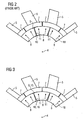
- Figure 2 shows an arrangement of prior art locking plates 8 around an axis of rotation 4 of a rotor disc 2, having gap spaces 11 with parallel longitudinal sides, thus the first and second gaps 9,10 at the ends of the gap spaces are equal.
- the locking plates exert a centrifugal force 18 directed away from the center of rotation upon the annular grooves 13 of the blades 5 and align with the corresponding blades.
- the gap spaces 11 should be close enough to reduce leakage. But they also should allow for articulation.
- On the left side of Figure 2 the gap space is large and leakage is high.
- the gap space is small and does not allow for articulation.
- the locking plates cannot cope with transients and will lock up (dashed lines).
- Figure 3 shows an arrangement of the inventive locking plates 8 around an axis of rotation 4. Assembly and positioning of locking plates is as in prior art. However, the longitudinal sides of gaps spaces 11 formed by two neighbouring inventive locking plates 8 are not parallel but tapered so that smaller gaps 9 are on the radially outside edges and larger gaps 10 on the radially inside edges. The locking plates are allowed to articulate and to align (dashed lines) with the corresponding blades 5 without locking up.
Landscapes
- Engineering & Computer Science (AREA)
- Mechanical Engineering (AREA)
- General Engineering & Computer Science (AREA)
- Turbine Rotor Nozzle Sealing (AREA)
Claims (6)
- Rotor de turbine (1), comprenant :un disque de rotor (2) ;une pluralité de fentes (3) agencées sur le disque de rotor (2) ;une pluralité d'ailettes (5) ayant des emplantures (6) d'ailettes et agencées dans les fentes (3) ; etune pluralité de plaques de verrouillage (8) disposées dans une position entre le disque de rotor (2) et les ailettes (5), dans lequel des premiers espaces (9) sur des extrémités radialement extérieures et des deuxièmes espaces (10) sur des extrémités radialement intérieures, par rapport à un axe de rotation (4) du disque de rotor (2), sont formés entre plaques de verrouillage (8) voisines, au moins un des premiers espaces (9) étant plus petit que le deuxième espace (10) correspondant.
- Rotor de turbine (1) selon la revendication 1, dans lequel le rapport d'au moins un deuxième espace (10) sur un premier espace (9) correspondant est dans la plage entre 1,1:1 à 10:1.
- Rotor de turbine (1) selon la revendication 1, dans lequel la majorité, en particulier la totalité, des premiers espaces (9) sont plus petits que les deuxièmes espaces (10) correspondants.
- Rotor de turbine (1) selon la revendication 1, dans lequel les plaques de verrouillage (8) s'étendent circonférentiellement par-dessus au moins deux moitiés voisines d'emplantures (6) d'ailettes, les plaques de verrouillage (8) étant dimensionnées et configurées pour recouvrir et fermer de façon étanche des espaces entre les emplantures (6) d'ailettes et le disque de rotor (2).
- Rotor de turbine (1) selon la revendication 1, dans lequel les plaques de verrouillage (8) sont, dans la position assemblée, agencées entre des rainures annulaires de maintien (12, 13) agencées dans le disque de rotor (2) et les ailettes (5).
- Procédé d'agencement de plaques de verrouillage (8) sur un disque de rotor (2), comprenant :l'agencement d'une première plaque de verrouillage (8) sur une périphérie (14) du disque de rotor (2) ; etl'agencement d'une deuxième plaque de verrouillage (8) immédiatement à côté de la première plaque de verrouillage (8), dans lequel un espace (11) entre la première et la deuxième plaque de verrouillage (8) est formé, l'espace (11) ayant une extrémité étroite et une extrémité large (15, 16), l'extrémité large (16) étant agencée plus près de la périphérie (14) que l'extrémité étroite (15).
Priority Applications (8)
| Application Number | Priority Date | Filing Date | Title |
|---|---|---|---|
| DE602006006452T DE602006006452D1 (de) | 2006-09-25 | 2006-09-25 | Turbinenrotor mit Verschlussplatten und entsprechendes Montageverfahren |
| ES06020048T ES2321862T3 (es) | 2006-09-25 | 2006-09-25 | Rotor de turbina con placas de bloqueo y correspondiente procedimiento de montaje. |
| EP06020048A EP1905955B1 (fr) | 2006-09-25 | 2006-09-25 | Rotor de turbine avec plaques de verrouillage et procédé d'assemblage associé |
| PCT/EP2007/058740 WO2008037550A1 (fr) | 2006-09-25 | 2007-08-22 | Rotor de turbine avec des plaques de verrouillage et procédé d'assemblage correspondant |
| CN201510077460.9A CN104727859B (zh) | 2006-09-25 | 2007-08-22 | 具有锁定板的涡轮转子及相应的组装方法 |
| CN200780035333.6A CN101517200A (zh) | 2006-09-25 | 2007-08-22 | 具有锁定板的涡轮转子及相应的组装方法 |
| RU2009115699/06A RU2403404C1 (ru) | 2006-09-25 | 2007-08-22 | Ротор турбины со стопорными пластинками и соответствующий способ сборки |
| US12/311,255 US8128373B2 (en) | 2006-09-25 | 2007-08-22 | Turbine rotor with locking plates and corresponding assembly method |
Applications Claiming Priority (1)
| Application Number | Priority Date | Filing Date | Title |
|---|---|---|---|
| EP06020048A EP1905955B1 (fr) | 2006-09-25 | 2006-09-25 | Rotor de turbine avec plaques de verrouillage et procédé d'assemblage associé |
Publications (2)
| Publication Number | Publication Date |
|---|---|
| EP1905955A1 EP1905955A1 (fr) | 2008-04-02 |
| EP1905955B1 true EP1905955B1 (fr) | 2009-04-22 |
Family
ID=37632332
Family Applications (1)
| Application Number | Title | Priority Date | Filing Date |
|---|---|---|---|
| EP06020048A Active EP1905955B1 (fr) | 2006-09-25 | 2006-09-25 | Rotor de turbine avec plaques de verrouillage et procédé d'assemblage associé |
Country Status (7)
| Country | Link |
|---|---|
| US (1) | US8128373B2 (fr) |
| EP (1) | EP1905955B1 (fr) |
| CN (2) | CN101517200A (fr) |
| DE (1) | DE602006006452D1 (fr) |
| ES (1) | ES2321862T3 (fr) |
| RU (1) | RU2403404C1 (fr) |
| WO (1) | WO2008037550A1 (fr) |
Families Citing this family (21)
| Publication number | Priority date | Publication date | Assignee | Title |
|---|---|---|---|---|
| EP1916389A1 (fr) * | 2006-10-26 | 2008-04-30 | Siemens Aktiengesellschaft | Assemblage d'aubes de turbine |
| FR2918106B1 (fr) * | 2007-06-27 | 2011-05-06 | Snecma | Dispositif de retenue axiale d'aubes montees sur un disque de rotor de turbomachine. |
| US20100232939A1 (en) * | 2009-03-12 | 2010-09-16 | General Electric Company | Machine Seal Assembly |
| US8523529B2 (en) | 2009-11-11 | 2013-09-03 | General Electric Company | Locking spacer assembly for a circumferential entry airfoil attachment system |
| US9109457B2 (en) * | 2010-09-03 | 2015-08-18 | Siemens Energy, Inc. | Axial locking seals for aft removable turbine blade |
| US9127563B2 (en) * | 2011-04-05 | 2015-09-08 | General Electric Company | Locking device arrangement for a rotating bladed stage |
| US8764402B2 (en) * | 2011-06-09 | 2014-07-01 | General Electric Company | Turbomachine blade locking system |
| US9605552B2 (en) | 2013-06-10 | 2017-03-28 | General Electric Company | Non-integral segmented angel-wing seal |
| EP2940249A1 (fr) * | 2014-04-29 | 2015-11-04 | Siemens Aktiengesellschaft | Agencement de disque de roue et procédé de montage d'un agencement de disque de roue |
| US10371884B2 (en) * | 2014-08-04 | 2019-08-06 | Dolby Laboratories Licensing Corporation | Tiled assemblies for a high dynamic range display panel |
| CN106271378B (zh) * | 2015-06-09 | 2018-08-21 | 上海汽轮机厂有限公司 | 汽轮机转子上的动叶片装配方法 |
| CN105134303B (zh) * | 2015-09-15 | 2017-01-04 | 北京航空航天大学 | 一种成对矩形齿配合的涡轮叶片缘板 |
| CN108049921B (zh) * | 2017-11-27 | 2019-07-16 | 大连理工大学 | 一种航空发动机低压涡轮轴-盘组件的装配方法 |
| CN109707464A (zh) * | 2018-12-14 | 2019-05-03 | 北京全四维动力科技有限公司 | 用于保护蒸汽轮机叶片叶根和轮槽的组合装置 |
| CN110578557A (zh) * | 2019-10-29 | 2019-12-17 | 北京动力机械研究所 | 一种涡轮叶片锁紧装置及其装配方法 |
| US11565352B2 (en) * | 2019-11-15 | 2023-01-31 | Rolls-Royce Corporation | Techniques and assemblies for joining components using solid retainer materials |
| CN111561394B (zh) * | 2020-05-25 | 2021-07-09 | 中国航发沈阳发动机研究所 | 一种发动机进气机匣的结构及其装配方法 |
| CN114076000B (zh) * | 2020-08-17 | 2024-05-07 | 中国航发商用航空发动机有限责任公司 | 叶片轴向限位装置、叶盘结构以及燃气轮机 |
| US11168615B1 (en) * | 2020-08-25 | 2021-11-09 | Raytheon Technologies Corporation | Double ring axial sealing design |
| US11592362B2 (en) * | 2020-09-24 | 2023-02-28 | General Electric Company | System and method for full-scale sampling to conduct material tests on a steam turbine rotor |
| CN116624231A (zh) * | 2023-07-18 | 2023-08-22 | 中国航发燃气轮机有限公司 | 一种涡轮叶片及其设计方法 |
Family Cites Families (16)
| Publication number | Priority date | Publication date | Assignee | Title |
|---|---|---|---|---|
| GB806033A (en) * | 1955-09-26 | 1958-12-17 | Rolls Royce | Improvements in or relating to fluid machines having bladed rotors |
| US3318573A (en) * | 1964-08-19 | 1967-05-09 | Director Of Nat Aerospace Lab | Apparatus for maintaining rotor disc of gas turbine engine at a low temperature |
| US3748060A (en) * | 1971-09-14 | 1973-07-24 | Westinghouse Electric Corp | Sideplate for turbine blade |
| US3853425A (en) * | 1973-09-07 | 1974-12-10 | Westinghouse Electric Corp | Turbine rotor blade cooling and sealing system |
| SU533738A1 (ru) | 1974-04-29 | 1976-10-30 | Предприятие П/Я Г-4561 | Устройство дл фиксации лопаток в диске турбомашины |
| GB1479332A (en) * | 1974-11-06 | 1977-07-13 | Rolls Royce | Means for retaining blades to a disc or like structure |
| GB1512882A (en) * | 1976-02-11 | 1978-06-01 | Rolls Royce | Bladed rotor assembly for a gas turbine engine |
| US4275990A (en) * | 1977-12-17 | 1981-06-30 | Rolls-Royce Limited | Disc channel for cooling rotor blade roots |
| FR2419389A1 (fr) * | 1978-03-08 | 1979-10-05 | Snecma | Perfectionnements aux flasques de rotors de turbomachines |
| CA1198986A (fr) * | 1983-12-22 | 1986-01-07 | United Technologies Corporation | Rotor a refroidissement double passe en racine des aubes |
| US4915587A (en) * | 1988-10-24 | 1990-04-10 | Westinghouse Electric Corp. | Apparatus for locking side entry blades into a rotor |
| GB2258273B (en) * | 1991-08-02 | 1994-08-10 | Ruston Gas Turbines Ltd | Rotor blade locking arrangement |
| US5211407A (en) * | 1992-04-30 | 1993-05-18 | General Electric Company | Compressor rotor cross shank leak seal for axial dovetails |
| GB2302711A (en) * | 1995-06-26 | 1997-01-29 | Bmw Rolls Royce Gmbh | A turbine disc with blade seal plates |
| GB9517369D0 (en) * | 1995-08-24 | 1995-10-25 | Rolls Royce Plc | Bladed rotor |
| DE102004054930A1 (de) * | 2004-11-13 | 2006-05-18 | Mtu Aero Engines Gmbh | Rotor einer Turbomaschine, insbesondere Gasturbinenrotor |
-
2006
- 2006-09-25 DE DE602006006452T patent/DE602006006452D1/de active Active
- 2006-09-25 ES ES06020048T patent/ES2321862T3/es active Active
- 2006-09-25 EP EP06020048A patent/EP1905955B1/fr active Active
-
2007
- 2007-08-22 US US12/311,255 patent/US8128373B2/en active Active
- 2007-08-22 CN CN200780035333.6A patent/CN101517200A/zh active Pending
- 2007-08-22 WO PCT/EP2007/058740 patent/WO2008037550A1/fr not_active Ceased
- 2007-08-22 RU RU2009115699/06A patent/RU2403404C1/ru active
- 2007-08-22 CN CN201510077460.9A patent/CN104727859B/zh active Active
Also Published As
| Publication number | Publication date |
|---|---|
| DE602006006452D1 (de) | 2009-06-04 |
| CN104727859A (zh) | 2015-06-24 |
| US8128373B2 (en) | 2012-03-06 |
| ES2321862T3 (es) | 2009-06-12 |
| WO2008037550A1 (fr) | 2008-04-03 |
| CN104727859B (zh) | 2019-02-05 |
| US20100014978A1 (en) | 2010-01-21 |
| RU2403404C1 (ru) | 2010-11-10 |
| EP1905955A1 (fr) | 2008-04-02 |
| CN101517200A (zh) | 2009-08-26 |
Similar Documents
| Publication | Publication Date | Title |
|---|---|---|
| US8128373B2 (en) | Turbine rotor with locking plates and corresponding assembly method | |
| JP5112126B2 (ja) | ターボ機械ファン用のロータリアセンブリ | |
| EP2503098B1 (fr) | Ensemble de disque de rotor et ensemble de blocage à cet effet | |
| EP2580432B1 (fr) | Ensemble joint d'étanchéité pour aube de turbine | |
| US8215914B2 (en) | Compliant seal for rotor slot | |
| JP5185426B2 (ja) | ターボ機械のロータのためのロータセクション | |
| JP5711502B2 (ja) | 円周方向差込み型翼形部取付けシステム用の固定保持用スペーサ組立体 | |
| CA1164348A (fr) | Organe d'orientation de l'ecoulement pour turbomoteur a gaz | |
| US4432697A (en) | Rotor of axial-flow machine | |
| JP2680651B2 (ja) | ターボマシンのロータ用ブレード間のシール | |
| EP2660426B1 (fr) | Ensemble turbine | |
| JP6408888B2 (ja) | タービンバケット閉鎖組立体及びその組立方法 | |
| EP2149674B1 (fr) | Rotor aubagé de turbine avec amortisseur de vibrations | |
| EP1916389A1 (fr) | Assemblage d'aubes de turbine | |
| US8388310B1 (en) | Turbine disc sealing assembly | |
| EP2568121B1 (fr) | Support conique en gradin de garniture d'étanchéité et joint annulaire associé | |
| EP1705341B1 (fr) | Segment d'anneau pour monter des aubes variables de guidage | |
| EP1111193B1 (fr) | Système de verrouillage axial des aubes de turbomachines | |
| CN109154201B (zh) | 用于轴向进入式轮叶的边缘轮叶燕尾件径向支撑结构 | |
| US7708529B2 (en) | Rotor of a turbo engine, e.g., a gas turbine rotor | |
| US7780398B2 (en) | Bladed stator for a turbo-engine | |
| US20060275124A1 (en) | Methods and systems for assembling shrouded turbine bucket and tangential entry dovetail | |
| EP2639403B1 (fr) | Ensemble arbre pour moteur à turbine à gaz | |
| US20110182721A1 (en) | Sealing arrangement for a gas turbine engine | |
| US6010304A (en) | Blade retention system for a variable rotor blade |
Legal Events
| Date | Code | Title | Description |
|---|---|---|---|
| PUAI | Public reference made under article 153(3) epc to a published international application that has entered the european phase |
Free format text: ORIGINAL CODE: 0009012 |
|
| AK | Designated contracting states |
Kind code of ref document: A1 Designated state(s): AT BE BG CH CY CZ DE DK EE ES FI FR GB GR HU IE IS IT LI LT LU LV MC NL PL PT RO SE SI SK TR |
|
| AX | Request for extension of the european patent |
Extension state: AL BA HR MK YU |
|
| GRAP | Despatch of communication of intention to grant a patent |
Free format text: ORIGINAL CODE: EPIDOSNIGR1 |
|
| GRAP | Despatch of communication of intention to grant a patent |
Free format text: ORIGINAL CODE: EPIDOSNIGR1 |
|
| 17P | Request for examination filed |
Effective date: 20080929 |
|
| AKX | Designation fees paid |
Designated state(s): DE ES FR GB IT |
|
| GRAS | Grant fee paid |
Free format text: ORIGINAL CODE: EPIDOSNIGR3 |
|
| GRAA | (expected) grant |
Free format text: ORIGINAL CODE: 0009210 |
|
| AK | Designated contracting states |
Kind code of ref document: B1 Designated state(s): DE ES FR GB IT |
|
| REG | Reference to a national code |
Ref country code: GB Ref legal event code: FG4D |
|
| REF | Corresponds to: |
Ref document number: 602006006452 Country of ref document: DE Date of ref document: 20090604 Kind code of ref document: P |
|
| REG | Reference to a national code |
Ref country code: ES Ref legal event code: FG2A Ref document number: 2321862 Country of ref document: ES Kind code of ref document: T3 |
|
| PLBE | No opposition filed within time limit |
Free format text: ORIGINAL CODE: 0009261 |
|
| STAA | Information on the status of an ep patent application or granted ep patent |
Free format text: STATUS: NO OPPOSITION FILED WITHIN TIME LIMIT |
|
| 26N | No opposition filed |
Effective date: 20100125 |
|
| REG | Reference to a national code |
Ref country code: FR Ref legal event code: PLFP Year of fee payment: 11 |
|
| REG | Reference to a national code |
Ref country code: FR Ref legal event code: PLFP Year of fee payment: 12 |
|
| PGFP | Annual fee paid to national office [announced via postgrant information from national office to epo] |
Ref country code: ES Payment date: 20171226 Year of fee payment: 12 |
|
| REG | Reference to a national code |
Ref country code: FR Ref legal event code: PLFP Year of fee payment: 13 |
|
| REG | Reference to a national code |
Ref country code: ES Ref legal event code: FD2A Effective date: 20191104 |
|
| PG25 | Lapsed in a contracting state [announced via postgrant information from national office to epo] |
Ref country code: ES Free format text: LAPSE BECAUSE OF NON-PAYMENT OF DUE FEES Effective date: 20180926 |
|
| REG | Reference to a national code |
Ref country code: DE Ref legal event code: R081 Ref document number: 602006006452 Country of ref document: DE Owner name: SIEMENS ENERGY GLOBAL GMBH & CO. KG, DE Free format text: FORMER OWNER: SIEMENS AKTIENGESELLSCHAFT, 80333 MUENCHEN, DE |
|
| REG | Reference to a national code |
Ref country code: GB Ref legal event code: 732E Free format text: REGISTERED BETWEEN 20220811 AND 20220817 |
|
| P01 | Opt-out of the competence of the unified patent court (upc) registered |
Effective date: 20231222 |
|
| PGFP | Annual fee paid to national office [announced via postgrant information from national office to epo] |
Ref country code: DE Payment date: 20250926 Year of fee payment: 20 |
|
| PGFP | Annual fee paid to national office [announced via postgrant information from national office to epo] |
Ref country code: IT Payment date: 20250922 Year of fee payment: 20 |
|
| PGFP | Annual fee paid to national office [announced via postgrant information from national office to epo] |
Ref country code: GB Payment date: 20250923 Year of fee payment: 20 |
|
| PGFP | Annual fee paid to national office [announced via postgrant information from national office to epo] |
Ref country code: FR Payment date: 20250925 Year of fee payment: 20 |