EP1905977A2 - Agencement d'échangeur thermique à thermostat, en particulier pour un échangeur thermique d'un véhicule automobile - Google Patents
Agencement d'échangeur thermique à thermostat, en particulier pour un échangeur thermique d'un véhicule automobile Download PDFInfo
- Publication number
- EP1905977A2 EP1905977A2 EP07017071A EP07017071A EP1905977A2 EP 1905977 A2 EP1905977 A2 EP 1905977A2 EP 07017071 A EP07017071 A EP 07017071A EP 07017071 A EP07017071 A EP 07017071A EP 1905977 A2 EP1905977 A2 EP 1905977A2
- Authority
- EP
- European Patent Office
- Prior art keywords
- heat exchanger
- thermostat
- coolant
- arrangement according
- charge air
- Prior art date
- Legal status (The legal status is an assumption and is not a legal conclusion. Google has not performed a legal analysis and makes no representation as to the accuracy of the status listed.)
- Granted
Links
Images

Classifications
-
- F—MECHANICAL ENGINEERING; LIGHTING; HEATING; WEAPONS; BLASTING
- F02—COMBUSTION ENGINES; HOT-GAS OR COMBUSTION-PRODUCT ENGINE PLANTS
- F02B—INTERNAL-COMBUSTION PISTON ENGINES; COMBUSTION ENGINES IN GENERAL
- F02B29/00—Engines characterised by provision for charging or scavenging not provided for in groups F02B25/00, F02B27/00 or F02B33/00 - F02B39/00; Details thereof
- F02B29/04—Cooling of air intake supply
- F02B29/045—Constructional details of the heat exchangers, e.g. pipes, plates, ribs, insulation, materials, or manufacturing and assembly
- F02B29/0475—Constructional details of the heat exchangers, e.g. pipes, plates, ribs, insulation, materials, or manufacturing and assembly the intake air cooler being combined with another device, e.g. heater, valve, compressor, filter or EGR cooler, or being assembled on a special engine location
-
- F—MECHANICAL ENGINEERING; LIGHTING; HEATING; WEAPONS; BLASTING
- F02—COMBUSTION ENGINES; HOT-GAS OR COMBUSTION-PRODUCT ENGINE PLANTS
- F02B—INTERNAL-COMBUSTION PISTON ENGINES; COMBUSTION ENGINES IN GENERAL
- F02B29/00—Engines characterised by provision for charging or scavenging not provided for in groups F02B25/00, F02B27/00 or F02B33/00 - F02B39/00; Details thereof
- F02B29/04—Cooling of air intake supply
- F02B29/045—Constructional details of the heat exchangers, e.g. pipes, plates, ribs, insulation, materials, or manufacturing and assembly
- F02B29/0462—Liquid cooled heat exchangers
-
- F—MECHANICAL ENGINEERING; LIGHTING; HEATING; WEAPONS; BLASTING
- F02—COMBUSTION ENGINES; HOT-GAS OR COMBUSTION-PRODUCT ENGINE PLANTS
- F02B—INTERNAL-COMBUSTION PISTON ENGINES; COMBUSTION ENGINES IN GENERAL
- F02B29/00—Engines characterised by provision for charging or scavenging not provided for in groups F02B25/00, F02B27/00 or F02B33/00 - F02B39/00; Details thereof
- F02B29/04—Cooling of air intake supply
- F02B29/0493—Controlling the air charge temperature
-
- Y—GENERAL TAGGING OF NEW TECHNOLOGICAL DEVELOPMENTS; GENERAL TAGGING OF CROSS-SECTIONAL TECHNOLOGIES SPANNING OVER SEVERAL SECTIONS OF THE IPC; TECHNICAL SUBJECTS COVERED BY FORMER USPC CROSS-REFERENCE ART COLLECTIONS [XRACs] AND DIGESTS
- Y02—TECHNOLOGIES OR APPLICATIONS FOR MITIGATION OR ADAPTATION AGAINST CLIMATE CHANGE
- Y02T—CLIMATE CHANGE MITIGATION TECHNOLOGIES RELATED TO TRANSPORTATION
- Y02T10/00—Road transport of goods or passengers
- Y02T10/10—Internal combustion engine [ICE] based vehicles
- Y02T10/12—Improving ICE efficiencies
Definitions
- the invention relates to a thermostat-heat exchanger arrangement, in particular for a heat exchanger of a motor vehicle according to the preamble of claim 1.
- a hose thermostat also referred to as a hose valve
- a hose valve is often used to control thedemitteistroms.
- This can be arranged, for example, coolant outlet side of a heat exchanger, in particular a charge air cooler, in a low-temperature cooling circuit.
- thermostatic heat exchanger assemblies leave desires in terms of the shortest possible response time open.
- a thermostat-heat exchanger arrangement in particular for a in a secondary coolant circuit of a charge air cooler, with a heat exchanger, a thermostat, which is arranged in the region of an inlet or outlet to or from the heat exchanger and a fluid flow, in particular a coolant flow, regulated as a function of the temperature, provided, wherein the thermostat is built into a wall of the heat exchanger integrated. Due to the integrated design, the housing of the thermostat can be omitted.
- this embodiment in addition to a reduction in the installation space, also enables a shortened reaction time to temperature changes of the coolant, resulting in improved control behavior.
- the wall in which the thermostat is preferably integrated is an outer wall of the heat exchanger. An attachment to this is usually possible without much effort. Likewise, a relative seal is possible.
- the thermostat is preferably arranged in an outlet opening of the heat exchanger.
- the region of the thermostat in which there is a medium with a temperature-dependent volume, preferably extends into the outlet opening.
- the thermostat extends at least partially within the heat exchanger, so that space can be saved to the outside.
- a part of the thermostat preferably also extends slightly outwards.
- the heat exchanger is preferably a disk-type heat exchanger, wherein the thermostat is arranged in an opening in a connection plate or a bottom plate of the heat exchanger and fixed to the same or the same.
- other heat exchangers can be designed accordingly for receiving a thermostat.
- an edge of the thermostat is arranged in a groove and fixed with the interposition of a seal from the outside by means of a yoke or other connection of a connecting line.
- the heat exchanger is particularly preferably a charge air cooler. This is preferably flowed through by a coolant, wherein the coolant circuit may also be connected to the engine coolant circuit.
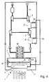
- FIG. 4 shows a basically known two-stage intercooling with associated coolant circuit 1, subdivided into a main coolant circuit 1 '. and a sub-coolant circuit 1 ", wherein the coolant circuit 1, the cooling of a motor M and the cooling of charge air LL is used.
- the air drawn in from the surroundings is compressed by a first turbocharger 2, which heats the air.
- a subsequent low-pressure charge air cooler 3 which will be discussed in more detail later, the hot air is cooled.
- a second turbocharger 4 the cooled, precompressed air is further compressed and then the hot charge air is cooled in a subsequent high-pressure charge air cooler 5 before it reaches the engine M and is burned in the same.
- the exhaust gas thus produced flows through two turbines for energy recovery and passes through a particle filter to the outside.
- the coolant circuit 1 is circulated by a pump P, the circuit dividing directly after the pump P into the main coolant circuit 1 'and the secondary coolant circuit 1 ".
- the coolant first flows through the engine M to a valve 6, which directs the coolant as a function of the temperature and the engine cooling requirement through a first coolant cooler 7 or through a bypass 8.
- the two parallel branches of the main coolant circuit 1 ' are brought together again and the coolant reaches Pump P.
- the entire coolant flowing through it is first passed through a second sub-coolant cooler 9, which is arranged parallel to the first coolant radiator 7. Both coolant coolers 7 and 9 are flowed through by means of a blower of cooling air from the environment
- the cooled coolant of the auxiliary coolant circuit 1 " is distributed downstream of the coolant radiator 9 as a function of the cooling demand on the two charge air coolers 3 and 5 via lines connected in parallel and flows through the same.
- the regulation of the coolant flow through the two charge air coolers 3 and 5 takes place by means of a respective integrated in each of the intercoolers 3 and 5 thermostat 10, which is arranged in the region of the outlet opening 11 of the respective intercooler 3 and 5 respectively.
- the two branches of the auxiliary coolant circuit 1 are brought together again and merge with the main coolant circuit 1 'in a region downstream of the coolant cooler 7 and before the bypass 8 is bypassed.
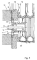
- thermostat 10 in the intercooler 3
- the configuration of the thermostat-heat exchanger arrangement in the case of the second intercooler 5 is corresponding, so that will not be discussed in more detail below.
- the intercooler 3 is a disc-type intercooler having a plurality of arcuate discs 13 which are assembled and form flow paths for heat transfer therebetween.
- the lowermost disc 13, shown on the left in FIG. 1, is also referred to below as a bottom plate and is somewhat stronger for stiffening.
- the thermostat 10 is arranged in the central longitudinal axis of the coolant outlet opening 11, wherein it extends into the intercooler 3 with about half of it into the second pair of disks. The other half of the thermostat 10 projects beyond the outer surface of the floor panel.
- connection plate 14 is attached, soldered in the present case, which has a circular opening in extension of the outlet opening 11.
- the connection plate 14 on the outside an annular groove 15 around the outlet opening 11.
- a flange 16 of the thermostat 10 is arranged.
- a sealing plate 17 arranged, annular, presently formed with two beads sealing element 18 inserted into the groove 14 and in the present past glued along the outer circumference, which extends beyond the outer edge of the flange 16 from the thermostat 10.
- the sealing plate 17 together with the sealing element 18 is pressed from above by a yoke 19 against the connection plate 14, for which holes 17 or other through holes for inserted through the sealing plate 17 and the yoke 19 and screwed into the connection plate 14 screws in the sealing plate.
- a connecting line (not shown) is connected, via which the coolant is fed back to the common part of the coolant circuit 1.
- the function of the thermostat 10 is as follows: starting from the maximum open state of the thermostat 10, cooler coolant flows through a portion 20 of the thermostat 10 which is displaceable between a region adjacent to the flange 16 of the thermostat 10 and a movable part 20 of the thermostat 10 which is displaceable in the longitudinal direction of the central longitudinal axis of the outlet opening 11
- a contained in a chamber 21 in the displaceable part 20 of the thermostat medium thereby changing its volume, preferably reduced, so that supported by the force of a spring 22, a pin 23 can continue to penetrate into the chamber 21, and slidable part 20 approaches the area adjacent to the flange 16 as a function of the temperature.
- the thermostat 10 has according to the present embodiment in its closed position, a leakage current of 100 to 200 I / h, so that even in this state, a sufficiently short reaction time can be guaranteed to temperature changes.
- thermostat does not necessarily have to correspond to the previously described embodiment.
- the thermostat be formed so that it extends only in the interior of the outlet opening and not on the connection plate to the outside.
- connection plate eliminates the connection plate.
- thermostat-heat exchanger arrangement in a cooler as a heat exchanger.
- a heat exchanger in disk construction does not necessarily have to be used as a heat exchanger.
- a corresponding integration of the thermostat in the heat exchanger can also be carried out, for example, in the case of a plate-type heat exchanger, in heat exchangers with box-shaped collectors, etc. In other applications, an inlet-side arrangement is conceivable.
Landscapes
- Engineering & Computer Science (AREA)
- Physics & Mathematics (AREA)
- Thermal Sciences (AREA)
- Chemical & Material Sciences (AREA)
- Combustion & Propulsion (AREA)
- Mechanical Engineering (AREA)
- General Engineering & Computer Science (AREA)
- Heat-Exchange Devices With Radiators And Conduit Assemblies (AREA)
Applications Claiming Priority (1)
| Application Number | Priority Date | Filing Date | Title |
|---|---|---|---|
| DE102006044155A DE102006044155A1 (de) | 2006-09-15 | 2006-09-15 | Thermostat-Wärmetauscher-Anordnung, insbesondere für einen Wärmetauscher eines Kraftfahrzeugs |
Publications (3)
| Publication Number | Publication Date |
|---|---|
| EP1905977A2 true EP1905977A2 (fr) | 2008-04-02 |
| EP1905977A3 EP1905977A3 (fr) | 2009-12-30 |
| EP1905977B1 EP1905977B1 (fr) | 2015-07-22 |
Family
ID=39004782
Family Applications (1)
| Application Number | Title | Priority Date | Filing Date |
|---|---|---|---|
| EP07017071.7A Active EP1905977B1 (fr) | 2006-09-15 | 2007-08-31 | Agencement d'échangeur thermique à thermostat, en particulier pour un échangeur thermique d'un véhicule automobile |
Country Status (2)
| Country | Link |
|---|---|
| EP (1) | EP1905977B1 (fr) |
| DE (1) | DE102006044155A1 (fr) |
Families Citing this family (3)
| Publication number | Priority date | Publication date | Assignee | Title |
|---|---|---|---|---|
| DE102010039810A1 (de) * | 2010-08-26 | 2012-03-01 | Behr Gmbh & Co. Kg | Kühlsystem und Kühlverfahren für ein Fahrzeug |
| DE102011080208A1 (de) * | 2011-08-01 | 2013-02-07 | Behr Gmbh & Co. Kg | Wärmetauschersystem und Verfahren zum Betreiben eines Wärmetauschersystems für ein Fahrzeug |
| JP6201886B2 (ja) * | 2014-01-06 | 2017-09-27 | 株式会社デンソー | 吸気冷却装置 |
Family Cites Families (9)
| Publication number | Priority date | Publication date | Assignee | Title |
|---|---|---|---|---|
| DE4112497A1 (de) * | 1991-04-17 | 1992-10-22 | Daimler Benz Ag | Fluessigkeitskuehlung fuer brennkraftmaschinen |
| DE19540591C2 (de) * | 1995-10-31 | 1999-05-20 | Behr Gmbh & Co | Verfahren zur Regelung der Volumenstromverteilung in einem Kühlmittelkreislauf für Kraftfahrzeuge mit Motor und Vorrichtung zur Durchführung des Verfahrens |
| DE19907267B4 (de) * | 1999-02-20 | 2005-08-04 | Mtu Friedrichshafen Gmbh | Kühlermodul für eine Brennkraftmaschine |
| ATE469292T1 (de) * | 2002-03-08 | 2010-06-15 | Behr Gmbh & Co Kg | Vorrichtung zur kühlung von ladeluft und verfahren zum betreiben einer derartigen vorrichtung |
| DE50311520D1 (de) * | 2002-05-15 | 2009-06-25 | Behr Gmbh & Co Kg | Schaltbarer abgaswaermetauscher |
| FR2846407B1 (fr) * | 2002-10-28 | 2006-01-06 | Valeo Thermique Moteur Sa | Echangeur de chaleur a regulation de flux, en particulier pour vehicules automobiles |
| ATE502193T1 (de) * | 2003-12-19 | 2011-04-15 | Behr Gmbh & Co Kg | Kreislaufanordnung zur kühlung von ladeluft und verfahren zum betreiben einer derartigen kreislaufanordnung |
| DE102005031228A1 (de) * | 2004-07-26 | 2006-02-16 | Behr Gmbh & Co. Kg | Kühlmittelkühler mit in einen der Wasserkästen integriertem Getriebeölkühler |
| DE502005007311D1 (de) * | 2004-10-29 | 2009-07-02 | Behr Gmbh & Co Kg | Klimaanlage mit Kältespeicher |
-
2006
- 2006-09-15 DE DE102006044155A patent/DE102006044155A1/de not_active Withdrawn
-
2007
- 2007-08-31 EP EP07017071.7A patent/EP1905977B1/fr active Active
Also Published As
| Publication number | Publication date |
|---|---|
| DE102006044155A1 (de) | 2008-03-27 |
| EP1905977B1 (fr) | 2015-07-22 |
| EP1905977A3 (fr) | 2009-12-30 |
Similar Documents
| Publication | Publication Date | Title |
|---|---|---|
| DE102004019554C5 (de) | Abgasrückführsystem für eine Verbrennungskraftmaschine | |
| EP1570168B1 (fr) | Dispositif de refroidissement | |
| DE102019215797B4 (de) | Steuerventil zum Steuern eines Kühlmittelkreislaufs für einen Ladeluftkühler | |
| DE102017124727A1 (de) | Steuerungsventil | |
| DE102014117513A1 (de) | Zylinderförmiger Wärmetauscher | |
| WO2004090303A1 (fr) | Dispositif de circuit pour refroidir l'air de suralimentation et procédé pour faire fonctionner un dispositif de ce type | |
| DE102012113111A1 (de) | Wärmetauscher für Fahrzeug | |
| DE102011057004A1 (de) | Wärmetauscher für ein Fahrzeug | |
| EP1923549B1 (fr) | Système de refroidissement pour un véhicule automobile | |
| EP2978948B1 (fr) | Module d'aspiration destiné à un moteur à combustion interne suralimenté | |
| EP3648997A1 (fr) | Installation frigorifique pour véhicule pourvue d'un circuit de réfrigération équipé d'un échangeur thermique et échangeur thermique conçu pour une telle installation frigorifique | |
| DE102019132022A1 (de) | Motorkühlmittelkühlsystem für ein Fahrzeug | |
| DE102015218105A1 (de) | Wärmeübertrager | |
| WO2004097194A2 (fr) | Circuit pour refroidir de l'air de suralimentation et procede d'exploitation d'un circuit de ce type | |
| WO2009000358A1 (fr) | Refroidisseur d'air de suralimentation pour un moteur à combustion interne | |
| DE102012011227A1 (de) | Verbrennungskraftmaschine für einen Kraftwagen | |
| DE102017006079A1 (de) | Kühleinrichtung für ein Kraftfahrzeug | |
| EP1905977B1 (fr) | Agencement d'échangeur thermique à thermostat, en particulier pour un échangeur thermique d'un véhicule automobile | |
| DE102010033125A1 (de) | Wärmetauschereinrichtung | |
| DE102018207621B3 (de) | Steuerventil für einen Kühlerkreislauf, Anordnung mit dem Steuerventilund Verfahren zum Steuern eines Flüssigkeitsstroms in der Anordnung | |
| DE102010006038A1 (de) | Vorrichtung zur Regelung eines Fluidstroms | |
| EP1673245B1 (fr) | Installation de climatisation comprenant une thermopompe | |
| DE102004024255A1 (de) | Anordnung in einem Kältemittelkreislauf und Arbeitsverfahren | |
| EP2194245A2 (fr) | Module de refroidissement de gaz d'échappement et d'huile pour un moteur à combustion interne | |
| DE102007035443A1 (de) | Vorichtung zur Kühlung von rückgeführtem Abgas eines Verbrennungsmotors |
Legal Events
| Date | Code | Title | Description |
|---|---|---|---|
| PUAI | Public reference made under article 153(3) epc to a published international application that has entered the european phase |
Free format text: ORIGINAL CODE: 0009012 |
|
| AK | Designated contracting states |
Kind code of ref document: A2 Designated state(s): AT BE BG CH CY CZ DE DK EE ES FI FR GB GR HU IE IS IT LI LT LU LV MC MT NL PL PT RO SE SI SK TR |
|
| AX | Request for extension of the european patent |
Extension state: AL BA HR MK YU |
|
| RIN1 | Information on inventor provided before grant (corrected) |
Inventor name: OBERLECHNER, CHRISTIAN Inventor name: WEGNER, JUERGEN, DIPL.-ING. (TU) Inventor name: VON LUETZAU, FRANK |
|
| PUAL | Search report despatched |
Free format text: ORIGINAL CODE: 0009013 |
|
| AK | Designated contracting states |
Kind code of ref document: A3 Designated state(s): AT BE BG CH CY CZ DE DK EE ES FI FR GB GR HU IE IS IT LI LT LU LV MC MT NL PL PT RO SE SI SK TR |
|
| AX | Request for extension of the european patent |
Extension state: AL BA HR MK RS |
|
| 17P | Request for examination filed |
Effective date: 20100630 |
|
| 17Q | First examination report despatched |
Effective date: 20100803 |
|
| AKX | Designation fees paid |
Designated state(s): AT BE BG CH CY CZ DE DK EE ES FI FR GB GR HU IE IS IT LI LT LU LV MC MT NL PL PT RO SE SI SK TR |
|
| GRAJ | Information related to disapproval of communication of intention to grant by the applicant or resumption of examination proceedings by the epo deleted |
Free format text: ORIGINAL CODE: EPIDOSDIGR1 |
|
| GRAP | Despatch of communication of intention to grant a patent |
Free format text: ORIGINAL CODE: EPIDOSNIGR1 |
|
| INTG | Intention to grant announced |
Effective date: 20141024 |
|
| GRAS | Grant fee paid |
Free format text: ORIGINAL CODE: EPIDOSNIGR3 |
|
| RAP1 | Party data changed (applicant data changed or rights of an application transferred) |
Owner name: MAHLE BEHR GMBH & CO. KG |
|
| RIN1 | Information on inventor provided before grant (corrected) |
Inventor name: WEGNER, JUERGEN, DIPL.-ING. (TU) Inventor name: OBERLECHNER, CHRISTIAN Inventor name: VON LUETZAU, FRANK |
|
| GRAP | Despatch of communication of intention to grant a patent |
Free format text: ORIGINAL CODE: EPIDOSNIGR1 |
|
| INTG | Intention to grant announced |
Effective date: 20150507 |
|
| GRAA | (expected) grant |
Free format text: ORIGINAL CODE: 0009210 |
|
| AK | Designated contracting states |
Kind code of ref document: B1 Designated state(s): AT BE BG CH CY CZ DE DK EE ES FI FR GB GR HU IE IS IT LI LT LU LV MC MT NL PL PT RO SE SI SK TR |
|
| REG | Reference to a national code |
Ref country code: GB Ref legal event code: FG4D Free format text: NOT ENGLISH |
|
| REG | Reference to a national code |
Ref country code: CH Ref legal event code: EP |
|
| REG | Reference to a national code |
Ref country code: IE Ref legal event code: FG4D Free format text: LANGUAGE OF EP DOCUMENT: GERMAN |
|
| REG | Reference to a national code |
Ref country code: AT Ref legal event code: REF Ref document number: 738072 Country of ref document: AT Kind code of ref document: T Effective date: 20150815 |
|
| REG | Reference to a national code |
Ref country code: FR Ref legal event code: PLFP Year of fee payment: 9 |
|
| REG | Reference to a national code |
Ref country code: DE Ref legal event code: R096 Ref document number: 502007014074 Country of ref document: DE |
|
| REG | Reference to a national code |
Ref country code: LT Ref legal event code: MG4D |
|
| REG | Reference to a national code |
Ref country code: NL Ref legal event code: MP Effective date: 20150722 |
|
| PG25 | Lapsed in a contracting state [announced via postgrant information from national office to epo] |
Ref country code: FI Free format text: LAPSE BECAUSE OF FAILURE TO SUBMIT A TRANSLATION OF THE DESCRIPTION OR TO PAY THE FEE WITHIN THE PRESCRIBED TIME-LIMIT Effective date: 20150722 Ref country code: GR Free format text: LAPSE BECAUSE OF FAILURE TO SUBMIT A TRANSLATION OF THE DESCRIPTION OR TO PAY THE FEE WITHIN THE PRESCRIBED TIME-LIMIT Effective date: 20151023 Ref country code: LT Free format text: LAPSE BECAUSE OF FAILURE TO SUBMIT A TRANSLATION OF THE DESCRIPTION OR TO PAY THE FEE WITHIN THE PRESCRIBED TIME-LIMIT Effective date: 20150722 Ref country code: LV Free format text: LAPSE BECAUSE OF FAILURE TO SUBMIT A TRANSLATION OF THE DESCRIPTION OR TO PAY THE FEE WITHIN THE PRESCRIBED TIME-LIMIT Effective date: 20150722 |
|
| PG25 | Lapsed in a contracting state [announced via postgrant information from national office to epo] |
Ref country code: ES Free format text: LAPSE BECAUSE OF FAILURE TO SUBMIT A TRANSLATION OF THE DESCRIPTION OR TO PAY THE FEE WITHIN THE PRESCRIBED TIME-LIMIT Effective date: 20150722 Ref country code: SE Free format text: LAPSE BECAUSE OF FAILURE TO SUBMIT A TRANSLATION OF THE DESCRIPTION OR TO PAY THE FEE WITHIN THE PRESCRIBED TIME-LIMIT Effective date: 20150722 Ref country code: PL Free format text: LAPSE BECAUSE OF FAILURE TO SUBMIT A TRANSLATION OF THE DESCRIPTION OR TO PAY THE FEE WITHIN THE PRESCRIBED TIME-LIMIT Effective date: 20150722 Ref country code: IS Free format text: LAPSE BECAUSE OF FAILURE TO SUBMIT A TRANSLATION OF THE DESCRIPTION OR TO PAY THE FEE WITHIN THE PRESCRIBED TIME-LIMIT Effective date: 20151122 Ref country code: PT Free format text: LAPSE BECAUSE OF FAILURE TO SUBMIT A TRANSLATION OF THE DESCRIPTION OR TO PAY THE FEE WITHIN THE PRESCRIBED TIME-LIMIT Effective date: 20151123 |
|
| REG | Reference to a national code |
Ref country code: CH Ref legal event code: PL |
|
| REG | Reference to a national code |
Ref country code: DE Ref legal event code: R097 Ref document number: 502007014074 Country of ref document: DE |
|
| PG25 | Lapsed in a contracting state [announced via postgrant information from national office to epo] |
Ref country code: SK Free format text: LAPSE BECAUSE OF FAILURE TO SUBMIT A TRANSLATION OF THE DESCRIPTION OR TO PAY THE FEE WITHIN THE PRESCRIBED TIME-LIMIT Effective date: 20150722 Ref country code: DK Free format text: LAPSE BECAUSE OF FAILURE TO SUBMIT A TRANSLATION OF THE DESCRIPTION OR TO PAY THE FEE WITHIN THE PRESCRIBED TIME-LIMIT Effective date: 20150722 Ref country code: MC Free format text: LAPSE BECAUSE OF FAILURE TO SUBMIT A TRANSLATION OF THE DESCRIPTION OR TO PAY THE FEE WITHIN THE PRESCRIBED TIME-LIMIT Effective date: 20150722 Ref country code: EE Free format text: LAPSE BECAUSE OF FAILURE TO SUBMIT A TRANSLATION OF THE DESCRIPTION OR TO PAY THE FEE WITHIN THE PRESCRIBED TIME-LIMIT Effective date: 20150722 Ref country code: CZ Free format text: LAPSE BECAUSE OF FAILURE TO SUBMIT A TRANSLATION OF THE DESCRIPTION OR TO PAY THE FEE WITHIN THE PRESCRIBED TIME-LIMIT Effective date: 20150722 Ref country code: IT Free format text: LAPSE BECAUSE OF FAILURE TO SUBMIT A TRANSLATION OF THE DESCRIPTION OR TO PAY THE FEE WITHIN THE PRESCRIBED TIME-LIMIT Effective date: 20150722 Ref country code: CH Free format text: LAPSE BECAUSE OF NON-PAYMENT OF DUE FEES Effective date: 20150831 Ref country code: LI Free format text: LAPSE BECAUSE OF NON-PAYMENT OF DUE FEES Effective date: 20150831 |
|
| PLBE | No opposition filed within time limit |
Free format text: ORIGINAL CODE: 0009261 |
|
| STAA | Information on the status of an ep patent application or granted ep patent |
Free format text: STATUS: NO OPPOSITION FILED WITHIN TIME LIMIT |
|
| PG25 | Lapsed in a contracting state [announced via postgrant information from national office to epo] |
Ref country code: RO Free format text: LAPSE BECAUSE OF FAILURE TO SUBMIT A TRANSLATION OF THE DESCRIPTION OR TO PAY THE FEE WITHIN THE PRESCRIBED TIME-LIMIT Effective date: 20150722 |
|
| REG | Reference to a national code |
Ref country code: IE Ref legal event code: MM4A |
|
| 26N | No opposition filed |
Effective date: 20160425 |
|
| GBPC | Gb: european patent ceased through non-payment of renewal fee |
Effective date: 20151022 |
|
| PG25 | Lapsed in a contracting state [announced via postgrant information from national office to epo] |
Ref country code: GB Free format text: LAPSE BECAUSE OF NON-PAYMENT OF DUE FEES Effective date: 20151022 Ref country code: IE Free format text: LAPSE BECAUSE OF NON-PAYMENT OF DUE FEES Effective date: 20150831 |
|
| REG | Reference to a national code |
Ref country code: FR Ref legal event code: PLFP Year of fee payment: 10 |
|
| PG25 | Lapsed in a contracting state [announced via postgrant information from national office to epo] |
Ref country code: SI Free format text: LAPSE BECAUSE OF FAILURE TO SUBMIT A TRANSLATION OF THE DESCRIPTION OR TO PAY THE FEE WITHIN THE PRESCRIBED TIME-LIMIT Effective date: 20150722 |
|
| REG | Reference to a national code |
Ref country code: AT Ref legal event code: MM01 Ref document number: 738072 Country of ref document: AT Kind code of ref document: T Effective date: 20150831 |
|
| PG25 | Lapsed in a contracting state [announced via postgrant information from national office to epo] |
Ref country code: AT Free format text: LAPSE BECAUSE OF NON-PAYMENT OF DUE FEES Effective date: 20150831 |
|
| PG25 | Lapsed in a contracting state [announced via postgrant information from national office to epo] |
Ref country code: MT Free format text: LAPSE BECAUSE OF FAILURE TO SUBMIT A TRANSLATION OF THE DESCRIPTION OR TO PAY THE FEE WITHIN THE PRESCRIBED TIME-LIMIT Effective date: 20150722 |
|
| PG25 | Lapsed in a contracting state [announced via postgrant information from national office to epo] |
Ref country code: BG Free format text: LAPSE BECAUSE OF FAILURE TO SUBMIT A TRANSLATION OF THE DESCRIPTION OR TO PAY THE FEE WITHIN THE PRESCRIBED TIME-LIMIT Effective date: 20150722 Ref country code: HU Free format text: LAPSE BECAUSE OF FAILURE TO SUBMIT A TRANSLATION OF THE DESCRIPTION OR TO PAY THE FEE WITHIN THE PRESCRIBED TIME-LIMIT; INVALID AB INITIO Effective date: 20070831 |
|
| PG25 | Lapsed in a contracting state [announced via postgrant information from national office to epo] |
Ref country code: NL Free format text: LAPSE BECAUSE OF FAILURE TO SUBMIT A TRANSLATION OF THE DESCRIPTION OR TO PAY THE FEE WITHIN THE PRESCRIBED TIME-LIMIT Effective date: 20150722 Ref country code: CY Free format text: LAPSE BECAUSE OF FAILURE TO SUBMIT A TRANSLATION OF THE DESCRIPTION OR TO PAY THE FEE WITHIN THE PRESCRIBED TIME-LIMIT Effective date: 20150722 |
|
| PG25 | Lapsed in a contracting state [announced via postgrant information from national office to epo] |
Ref country code: BE Free format text: LAPSE BECAUSE OF NON-PAYMENT OF DUE FEES Effective date: 20150831 |
|
| REG | Reference to a national code |
Ref country code: FR Ref legal event code: PLFP Year of fee payment: 11 |
|
| PG25 | Lapsed in a contracting state [announced via postgrant information from national office to epo] |
Ref country code: TR Free format text: LAPSE BECAUSE OF FAILURE TO SUBMIT A TRANSLATION OF THE DESCRIPTION OR TO PAY THE FEE WITHIN THE PRESCRIBED TIME-LIMIT Effective date: 20150722 |
|
| PG25 | Lapsed in a contracting state [announced via postgrant information from national office to epo] |
Ref country code: LU Free format text: LAPSE BECAUSE OF NON-PAYMENT OF DUE FEES Effective date: 20150831 |
|
| REG | Reference to a national code |
Ref country code: FR Ref legal event code: PLFP Year of fee payment: 12 |
|
| PGFP | Annual fee paid to national office [announced via postgrant information from national office to epo] |
Ref country code: DE Payment date: 20211018 Year of fee payment: 15 |
|
| REG | Reference to a national code |
Ref country code: DE Ref legal event code: R119 Ref document number: 502007014074 Country of ref document: DE |
|
| PG25 | Lapsed in a contracting state [announced via postgrant information from national office to epo] |
Ref country code: DE Free format text: LAPSE BECAUSE OF NON-PAYMENT OF DUE FEES Effective date: 20230301 |
|
| P01 | Opt-out of the competence of the unified patent court (upc) registered |
Effective date: 20240521 |
|
| PGFP | Annual fee paid to national office [announced via postgrant information from national office to epo] |
Ref country code: FR Payment date: 20250828 Year of fee payment: 19 |