EP1906076A2 - Schutzschicht für ein Druckgefäß - Google Patents
Schutzschicht für ein Druckgefäß Download PDFInfo
- Publication number
- EP1906076A2 EP1906076A2 EP07013924A EP07013924A EP1906076A2 EP 1906076 A2 EP1906076 A2 EP 1906076A2 EP 07013924 A EP07013924 A EP 07013924A EP 07013924 A EP07013924 A EP 07013924A EP 1906076 A2 EP1906076 A2 EP 1906076A2
- Authority
- EP
- European Patent Office
- Prior art keywords
- protective jacket
- support rim
- handles
- pressure vessel
- upper support
- Prior art date
- Legal status (The legal status is an assumption and is not a legal conclusion. Google has not performed a legal analysis and makes no representation as to the accuracy of the status listed.)
- Granted
Links
Images


Classifications
-
- F—MECHANICAL ENGINEERING; LIGHTING; HEATING; WEAPONS; BLASTING
- F17—STORING OR DISTRIBUTING GASES OR LIQUIDS
- F17C—VESSELS FOR CONTAINING OR STORING COMPRESSED, LIQUEFIED OR SOLIDIFIED GASES; FIXED-CAPACITY GAS-HOLDERS; FILLING VESSELS WITH, OR DISCHARGING FROM VESSELS, COMPRESSED, LIQUEFIED, OR SOLIDIFIED GASES
- F17C13/00—Details of vessels or of the filling or discharging of vessels
- F17C13/08—Mounting arrangements for vessels
- F17C13/084—Mounting arrangements for vessels for small-sized storage vessels, e.g. compressed gas cylinders or bottles, disposable gas vessels, vessels adapted for automotive use
-
- F—MECHANICAL ENGINEERING; LIGHTING; HEATING; WEAPONS; BLASTING
- F17—STORING OR DISTRIBUTING GASES OR LIQUIDS
- F17C—VESSELS FOR CONTAINING OR STORING COMPRESSED, LIQUEFIED OR SOLIDIFIED GASES; FIXED-CAPACITY GAS-HOLDERS; FILLING VESSELS WITH, OR DISCHARGING FROM VESSELS, COMPRESSED, LIQUEFIED, OR SOLIDIFIED GASES
- F17C1/00—Pressure vessels, e.g. gas cylinder, gas tank, replaceable cartridge
- F17C1/02—Pressure vessels, e.g. gas cylinder, gas tank, replaceable cartridge involving reinforcing arrangements
- F17C1/04—Protecting sheathings
- F17C1/06—Protecting sheathings built-up from wound-on bands or filamentary material, e.g. wires
-
- F—MECHANICAL ENGINEERING; LIGHTING; HEATING; WEAPONS; BLASTING
- F17—STORING OR DISTRIBUTING GASES OR LIQUIDS
- F17C—VESSELS FOR CONTAINING OR STORING COMPRESSED, LIQUEFIED OR SOLIDIFIED GASES; FIXED-CAPACITY GAS-HOLDERS; FILLING VESSELS WITH, OR DISCHARGING FROM VESSELS, COMPRESSED, LIQUEFIED, OR SOLIDIFIED GASES
- F17C1/00—Pressure vessels, e.g. gas cylinder, gas tank, replaceable cartridge
- F17C1/10—Pressure vessels, e.g. gas cylinder, gas tank, replaceable cartridge with provision for protection against corrosion, e.g. due to gaseous acid
-
- F—MECHANICAL ENGINEERING; LIGHTING; HEATING; WEAPONS; BLASTING
- F17—STORING OR DISTRIBUTING GASES OR LIQUIDS
- F17C—VESSELS FOR CONTAINING OR STORING COMPRESSED, LIQUEFIED OR SOLIDIFIED GASES; FIXED-CAPACITY GAS-HOLDERS; FILLING VESSELS WITH, OR DISCHARGING FROM VESSELS, COMPRESSED, LIQUEFIED, OR SOLIDIFIED GASES
- F17C13/00—Details of vessels or of the filling or discharging of vessels
- F17C13/002—Details of vessels or of the filling or discharging of vessels for vessels under pressure
- F17C13/003—Means for coding or identifying them and/or their contents
-
- F—MECHANICAL ENGINEERING; LIGHTING; HEATING; WEAPONS; BLASTING
- F17—STORING OR DISTRIBUTING GASES OR LIQUIDS
- F17C—VESSELS FOR CONTAINING OR STORING COMPRESSED, LIQUEFIED OR SOLIDIFIED GASES; FIXED-CAPACITY GAS-HOLDERS; FILLING VESSELS WITH, OR DISCHARGING FROM VESSELS, COMPRESSED, LIQUEFIED, OR SOLIDIFIED GASES
- F17C2201/00—Vessel construction, in particular geometry, arrangement or size
- F17C2201/01—Shape
- F17C2201/0104—Shape cylindrical
- F17C2201/0109—Shape cylindrical with exteriorly curved end-piece
-
- F—MECHANICAL ENGINEERING; LIGHTING; HEATING; WEAPONS; BLASTING
- F17—STORING OR DISTRIBUTING GASES OR LIQUIDS
- F17C—VESSELS FOR CONTAINING OR STORING COMPRESSED, LIQUEFIED OR SOLIDIFIED GASES; FIXED-CAPACITY GAS-HOLDERS; FILLING VESSELS WITH, OR DISCHARGING FROM VESSELS, COMPRESSED, LIQUEFIED, OR SOLIDIFIED GASES
- F17C2201/00—Vessel construction, in particular geometry, arrangement or size
- F17C2201/03—Orientation
- F17C2201/032—Orientation with substantially vertical main axis
-
- F—MECHANICAL ENGINEERING; LIGHTING; HEATING; WEAPONS; BLASTING
- F17—STORING OR DISTRIBUTING GASES OR LIQUIDS
- F17C—VESSELS FOR CONTAINING OR STORING COMPRESSED, LIQUEFIED OR SOLIDIFIED GASES; FIXED-CAPACITY GAS-HOLDERS; FILLING VESSELS WITH, OR DISCHARGING FROM VESSELS, COMPRESSED, LIQUEFIED, OR SOLIDIFIED GASES
- F17C2201/00—Vessel construction, in particular geometry, arrangement or size
- F17C2201/05—Size
- F17C2201/058—Size portable (<30 l)
-
- F—MECHANICAL ENGINEERING; LIGHTING; HEATING; WEAPONS; BLASTING
- F17—STORING OR DISTRIBUTING GASES OR LIQUIDS
- F17C—VESSELS FOR CONTAINING OR STORING COMPRESSED, LIQUEFIED OR SOLIDIFIED GASES; FIXED-CAPACITY GAS-HOLDERS; FILLING VESSELS WITH, OR DISCHARGING FROM VESSELS, COMPRESSED, LIQUEFIED, OR SOLIDIFIED GASES
- F17C2203/00—Vessel construction, in particular walls or details thereof
- F17C2203/06—Materials for walls or layers thereof; Properties or structures of walls or their materials
- F17C2203/0602—Wall structures; Special features thereof
- F17C2203/0604—Liners
-
- F—MECHANICAL ENGINEERING; LIGHTING; HEATING; WEAPONS; BLASTING
- F17—STORING OR DISTRIBUTING GASES OR LIQUIDS
- F17C—VESSELS FOR CONTAINING OR STORING COMPRESSED, LIQUEFIED OR SOLIDIFIED GASES; FIXED-CAPACITY GAS-HOLDERS; FILLING VESSELS WITH, OR DISCHARGING FROM VESSELS, COMPRESSED, LIQUEFIED, OR SOLIDIFIED GASES
- F17C2203/00—Vessel construction, in particular walls or details thereof
- F17C2203/06—Materials for walls or layers thereof; Properties or structures of walls or their materials
- F17C2203/0602—Wall structures; Special features thereof
- F17C2203/0607—Coatings
-
- F—MECHANICAL ENGINEERING; LIGHTING; HEATING; WEAPONS; BLASTING
- F17—STORING OR DISTRIBUTING GASES OR LIQUIDS
- F17C—VESSELS FOR CONTAINING OR STORING COMPRESSED, LIQUEFIED OR SOLIDIFIED GASES; FIXED-CAPACITY GAS-HOLDERS; FILLING VESSELS WITH, OR DISCHARGING FROM VESSELS, COMPRESSED, LIQUEFIED, OR SOLIDIFIED GASES
- F17C2203/00—Vessel construction, in particular walls or details thereof
- F17C2203/06—Materials for walls or layers thereof; Properties or structures of walls or their materials
- F17C2203/0602—Wall structures; Special features thereof
- F17C2203/0612—Wall structures
- F17C2203/0614—Single wall
- F17C2203/0619—Single wall with two layers
-
- F—MECHANICAL ENGINEERING; LIGHTING; HEATING; WEAPONS; BLASTING
- F17—STORING OR DISTRIBUTING GASES OR LIQUIDS
- F17C—VESSELS FOR CONTAINING OR STORING COMPRESSED, LIQUEFIED OR SOLIDIFIED GASES; FIXED-CAPACITY GAS-HOLDERS; FILLING VESSELS WITH, OR DISCHARGING FROM VESSELS, COMPRESSED, LIQUEFIED, OR SOLIDIFIED GASES
- F17C2203/00—Vessel construction, in particular walls or details thereof
- F17C2203/06—Materials for walls or layers thereof; Properties or structures of walls or their materials
- F17C2203/0602—Wall structures; Special features thereof
- F17C2203/0612—Wall structures
- F17C2203/0614—Single wall
- F17C2203/0621—Single wall with three layers
-
- F—MECHANICAL ENGINEERING; LIGHTING; HEATING; WEAPONS; BLASTING
- F17—STORING OR DISTRIBUTING GASES OR LIQUIDS
- F17C—VESSELS FOR CONTAINING OR STORING COMPRESSED, LIQUEFIED OR SOLIDIFIED GASES; FIXED-CAPACITY GAS-HOLDERS; FILLING VESSELS WITH, OR DISCHARGING FROM VESSELS, COMPRESSED, LIQUEFIED, OR SOLIDIFIED GASES
- F17C2203/00—Vessel construction, in particular walls or details thereof
- F17C2203/06—Materials for walls or layers thereof; Properties or structures of walls or their materials
- F17C2203/0602—Wall structures; Special features thereof
- F17C2203/0612—Wall structures
- F17C2203/0614—Single wall
- F17C2203/0624—Single wall with four or more layers
-
- F—MECHANICAL ENGINEERING; LIGHTING; HEATING; WEAPONS; BLASTING
- F17—STORING OR DISTRIBUTING GASES OR LIQUIDS
- F17C—VESSELS FOR CONTAINING OR STORING COMPRESSED, LIQUEFIED OR SOLIDIFIED GASES; FIXED-CAPACITY GAS-HOLDERS; FILLING VESSELS WITH, OR DISCHARGING FROM VESSELS, COMPRESSED, LIQUEFIED, OR SOLIDIFIED GASES
- F17C2203/00—Vessel construction, in particular walls or details thereof
- F17C2203/06—Materials for walls or layers thereof; Properties or structures of walls or their materials
- F17C2203/0634—Materials for walls or layers thereof
- F17C2203/0636—Metals
- F17C2203/0639—Steels
- F17C2203/0643—Stainless steels
-
- F—MECHANICAL ENGINEERING; LIGHTING; HEATING; WEAPONS; BLASTING
- F17—STORING OR DISTRIBUTING GASES OR LIQUIDS
- F17C—VESSELS FOR CONTAINING OR STORING COMPRESSED, LIQUEFIED OR SOLIDIFIED GASES; FIXED-CAPACITY GAS-HOLDERS; FILLING VESSELS WITH, OR DISCHARGING FROM VESSELS, COMPRESSED, LIQUEFIED, OR SOLIDIFIED GASES
- F17C2203/00—Vessel construction, in particular walls or details thereof
- F17C2203/06—Materials for walls or layers thereof; Properties or structures of walls or their materials
- F17C2203/0634—Materials for walls or layers thereof
- F17C2203/0636—Metals
- F17C2203/0646—Aluminium
-
- F—MECHANICAL ENGINEERING; LIGHTING; HEATING; WEAPONS; BLASTING
- F17—STORING OR DISTRIBUTING GASES OR LIQUIDS
- F17C—VESSELS FOR CONTAINING OR STORING COMPRESSED, LIQUEFIED OR SOLIDIFIED GASES; FIXED-CAPACITY GAS-HOLDERS; FILLING VESSELS WITH, OR DISCHARGING FROM VESSELS, COMPRESSED, LIQUEFIED, OR SOLIDIFIED GASES
- F17C2203/00—Vessel construction, in particular walls or details thereof
- F17C2203/06—Materials for walls or layers thereof; Properties or structures of walls or their materials
- F17C2203/0634—Materials for walls or layers thereof
- F17C2203/0658—Synthetics
- F17C2203/066—Plastics
-
- F—MECHANICAL ENGINEERING; LIGHTING; HEATING; WEAPONS; BLASTING
- F17—STORING OR DISTRIBUTING GASES OR LIQUIDS
- F17C—VESSELS FOR CONTAINING OR STORING COMPRESSED, LIQUEFIED OR SOLIDIFIED GASES; FIXED-CAPACITY GAS-HOLDERS; FILLING VESSELS WITH, OR DISCHARGING FROM VESSELS, COMPRESSED, LIQUEFIED, OR SOLIDIFIED GASES
- F17C2203/00—Vessel construction, in particular walls or details thereof
- F17C2203/06—Materials for walls or layers thereof; Properties or structures of walls or their materials
- F17C2203/0634—Materials for walls or layers thereof
- F17C2203/0658—Synthetics
- F17C2203/0663—Synthetics in form of fibers or filaments
-
- F—MECHANICAL ENGINEERING; LIGHTING; HEATING; WEAPONS; BLASTING
- F17—STORING OR DISTRIBUTING GASES OR LIQUIDS
- F17C—VESSELS FOR CONTAINING OR STORING COMPRESSED, LIQUEFIED OR SOLIDIFIED GASES; FIXED-CAPACITY GAS-HOLDERS; FILLING VESSELS WITH, OR DISCHARGING FROM VESSELS, COMPRESSED, LIQUEFIED, OR SOLIDIFIED GASES
- F17C2205/00—Vessel construction, in particular mounting arrangements, attachments or identifications means
- F17C2205/01—Mounting arrangements
- F17C2205/0103—Exterior arrangements
- F17C2205/0115—Dismountable protective hulls
-
- F—MECHANICAL ENGINEERING; LIGHTING; HEATING; WEAPONS; BLASTING
- F17—STORING OR DISTRIBUTING GASES OR LIQUIDS
- F17C—VESSELS FOR CONTAINING OR STORING COMPRESSED, LIQUEFIED OR SOLIDIFIED GASES; FIXED-CAPACITY GAS-HOLDERS; FILLING VESSELS WITH, OR DISCHARGING FROM VESSELS, COMPRESSED, LIQUEFIED, OR SOLIDIFIED GASES
- F17C2205/00—Vessel construction, in particular mounting arrangements, attachments or identifications means
- F17C2205/01—Mounting arrangements
- F17C2205/0123—Mounting arrangements characterised by number of vessels
- F17C2205/0126—One vessel
-
- F—MECHANICAL ENGINEERING; LIGHTING; HEATING; WEAPONS; BLASTING
- F17—STORING OR DISTRIBUTING GASES OR LIQUIDS
- F17C—VESSELS FOR CONTAINING OR STORING COMPRESSED, LIQUEFIED OR SOLIDIFIED GASES; FIXED-CAPACITY GAS-HOLDERS; FILLING VESSELS WITH, OR DISCHARGING FROM VESSELS, COMPRESSED, LIQUEFIED, OR SOLIDIFIED GASES
- F17C2205/00—Vessel construction, in particular mounting arrangements, attachments or identifications means
- F17C2205/01—Mounting arrangements
- F17C2205/0153—Details of mounting arrangements
- F17C2205/0157—Details of mounting arrangements for transport
- F17C2205/0165—Details of mounting arrangements for transport with handgrip
-
- F—MECHANICAL ENGINEERING; LIGHTING; HEATING; WEAPONS; BLASTING
- F17—STORING OR DISTRIBUTING GASES OR LIQUIDS
- F17C—VESSELS FOR CONTAINING OR STORING COMPRESSED, LIQUEFIED OR SOLIDIFIED GASES; FIXED-CAPACITY GAS-HOLDERS; FILLING VESSELS WITH, OR DISCHARGING FROM VESSELS, COMPRESSED, LIQUEFIED, OR SOLIDIFIED GASES
- F17C2205/00—Vessel construction, in particular mounting arrangements, attachments or identifications means
- F17C2205/01—Mounting arrangements
- F17C2205/0153—Details of mounting arrangements
- F17C2205/0169—Details of mounting arrangements stackable
-
- F—MECHANICAL ENGINEERING; LIGHTING; HEATING; WEAPONS; BLASTING
- F17—STORING OR DISTRIBUTING GASES OR LIQUIDS
- F17C—VESSELS FOR CONTAINING OR STORING COMPRESSED, LIQUEFIED OR SOLIDIFIED GASES; FIXED-CAPACITY GAS-HOLDERS; FILLING VESSELS WITH, OR DISCHARGING FROM VESSELS, COMPRESSED, LIQUEFIED, OR SOLIDIFIED GASES
- F17C2205/00—Vessel construction, in particular mounting arrangements, attachments or identifications means
- F17C2205/01—Mounting arrangements
- F17C2205/0153—Details of mounting arrangements
- F17C2205/0176—Details of mounting arrangements with ventilation
-
- F—MECHANICAL ENGINEERING; LIGHTING; HEATING; WEAPONS; BLASTING
- F17—STORING OR DISTRIBUTING GASES OR LIQUIDS
- F17C—VESSELS FOR CONTAINING OR STORING COMPRESSED, LIQUEFIED OR SOLIDIFIED GASES; FIXED-CAPACITY GAS-HOLDERS; FILLING VESSELS WITH, OR DISCHARGING FROM VESSELS, COMPRESSED, LIQUEFIED, OR SOLIDIFIED GASES
- F17C2205/00—Vessel construction, in particular mounting arrangements, attachments or identifications means
- F17C2205/01—Mounting arrangements
- F17C2205/0153—Details of mounting arrangements
- F17C2205/018—Supporting feet
-
- F—MECHANICAL ENGINEERING; LIGHTING; HEATING; WEAPONS; BLASTING
- F17—STORING OR DISTRIBUTING GASES OR LIQUIDS
- F17C—VESSELS FOR CONTAINING OR STORING COMPRESSED, LIQUEFIED OR SOLIDIFIED GASES; FIXED-CAPACITY GAS-HOLDERS; FILLING VESSELS WITH, OR DISCHARGING FROM VESSELS, COMPRESSED, LIQUEFIED, OR SOLIDIFIED GASES
- F17C2205/00—Vessel construction, in particular mounting arrangements, attachments or identifications means
- F17C2205/01—Mounting arrangements
- F17C2205/0153—Details of mounting arrangements
- F17C2205/0196—Details of mounting arrangements with shock absorbing means
-
- F—MECHANICAL ENGINEERING; LIGHTING; HEATING; WEAPONS; BLASTING
- F17—STORING OR DISTRIBUTING GASES OR LIQUIDS
- F17C—VESSELS FOR CONTAINING OR STORING COMPRESSED, LIQUEFIED OR SOLIDIFIED GASES; FIXED-CAPACITY GAS-HOLDERS; FILLING VESSELS WITH, OR DISCHARGING FROM VESSELS, COMPRESSED, LIQUEFIED, OR SOLIDIFIED GASES
- F17C2205/00—Vessel construction, in particular mounting arrangements, attachments or identifications means
- F17C2205/03—Fluid connections, filters, valves, closure means or other attachments
- F17C2205/0302—Fittings, valves, filters, or components in connection with the gas storage device
- F17C2205/0308—Protective caps
-
- F—MECHANICAL ENGINEERING; LIGHTING; HEATING; WEAPONS; BLASTING
- F17—STORING OR DISTRIBUTING GASES OR LIQUIDS
- F17C—VESSELS FOR CONTAINING OR STORING COMPRESSED, LIQUEFIED OR SOLIDIFIED GASES; FIXED-CAPACITY GAS-HOLDERS; FILLING VESSELS WITH, OR DISCHARGING FROM VESSELS, COMPRESSED, LIQUEFIED, OR SOLIDIFIED GASES
- F17C2205/00—Vessel construction, in particular mounting arrangements, attachments or identifications means
- F17C2205/05—Vessel or content identifications, e.g. labels
- F17C2205/054—Vessel or content identifications, e.g. labels by bar codes
-
- F—MECHANICAL ENGINEERING; LIGHTING; HEATING; WEAPONS; BLASTING
- F17—STORING OR DISTRIBUTING GASES OR LIQUIDS
- F17C—VESSELS FOR CONTAINING OR STORING COMPRESSED, LIQUEFIED OR SOLIDIFIED GASES; FIXED-CAPACITY GAS-HOLDERS; FILLING VESSELS WITH, OR DISCHARGING FROM VESSELS, COMPRESSED, LIQUEFIED, OR SOLIDIFIED GASES
- F17C2205/00—Vessel construction, in particular mounting arrangements, attachments or identifications means
- F17C2205/05—Vessel or content identifications, e.g. labels
- F17C2205/057—Vessel or content identifications, e.g. labels by chips
-
- F—MECHANICAL ENGINEERING; LIGHTING; HEATING; WEAPONS; BLASTING
- F17—STORING OR DISTRIBUTING GASES OR LIQUIDS
- F17C—VESSELS FOR CONTAINING OR STORING COMPRESSED, LIQUEFIED OR SOLIDIFIED GASES; FIXED-CAPACITY GAS-HOLDERS; FILLING VESSELS WITH, OR DISCHARGING FROM VESSELS, COMPRESSED, LIQUEFIED, OR SOLIDIFIED GASES
- F17C2205/00—Vessel construction, in particular mounting arrangements, attachments or identifications means
- F17C2205/05—Vessel or content identifications, e.g. labels
- F17C2205/058—Vessel or content identifications, e.g. labels by Radio Frequency Identification
-
- F—MECHANICAL ENGINEERING; LIGHTING; HEATING; WEAPONS; BLASTING
- F17—STORING OR DISTRIBUTING GASES OR LIQUIDS
- F17C—VESSELS FOR CONTAINING OR STORING COMPRESSED, LIQUEFIED OR SOLIDIFIED GASES; FIXED-CAPACITY GAS-HOLDERS; FILLING VESSELS WITH, OR DISCHARGING FROM VESSELS, COMPRESSED, LIQUEFIED, OR SOLIDIFIED GASES
- F17C2209/00—Vessel construction, in particular methods of manufacturing
- F17C2209/21—Shaping processes
- F17C2209/2154—Winding
- F17C2209/2163—Winding with a mandrel
-
- F—MECHANICAL ENGINEERING; LIGHTING; HEATING; WEAPONS; BLASTING
- F17—STORING OR DISTRIBUTING GASES OR LIQUIDS
- F17C—VESSELS FOR CONTAINING OR STORING COMPRESSED, LIQUEFIED OR SOLIDIFIED GASES; FIXED-CAPACITY GAS-HOLDERS; FILLING VESSELS WITH, OR DISCHARGING FROM VESSELS, COMPRESSED, LIQUEFIED, OR SOLIDIFIED GASES
- F17C2209/00—Vessel construction, in particular methods of manufacturing
- F17C2209/22—Assembling processes
- F17C2209/221—Welding
-
- F—MECHANICAL ENGINEERING; LIGHTING; HEATING; WEAPONS; BLASTING
- F17—STORING OR DISTRIBUTING GASES OR LIQUIDS
- F17C—VESSELS FOR CONTAINING OR STORING COMPRESSED, LIQUEFIED OR SOLIDIFIED GASES; FIXED-CAPACITY GAS-HOLDERS; FILLING VESSELS WITH, OR DISCHARGING FROM VESSELS, COMPRESSED, LIQUEFIED, OR SOLIDIFIED GASES
- F17C2209/00—Vessel construction, in particular methods of manufacturing
- F17C2209/22—Assembling processes
- F17C2209/225—Spraying
-
- F—MECHANICAL ENGINEERING; LIGHTING; HEATING; WEAPONS; BLASTING
- F17—STORING OR DISTRIBUTING GASES OR LIQUIDS
- F17C—VESSELS FOR CONTAINING OR STORING COMPRESSED, LIQUEFIED OR SOLIDIFIED GASES; FIXED-CAPACITY GAS-HOLDERS; FILLING VESSELS WITH, OR DISCHARGING FROM VESSELS, COMPRESSED, LIQUEFIED, OR SOLIDIFIED GASES
- F17C2221/00—Handled fluid, in particular type of fluid
- F17C2221/03—Mixtures
- F17C2221/032—Hydrocarbons
- F17C2221/035—Propane butane, e.g. LPG, GPL
-
- F—MECHANICAL ENGINEERING; LIGHTING; HEATING; WEAPONS; BLASTING
- F17—STORING OR DISTRIBUTING GASES OR LIQUIDS
- F17C—VESSELS FOR CONTAINING OR STORING COMPRESSED, LIQUEFIED OR SOLIDIFIED GASES; FIXED-CAPACITY GAS-HOLDERS; FILLING VESSELS WITH, OR DISCHARGING FROM VESSELS, COMPRESSED, LIQUEFIED, OR SOLIDIFIED GASES
- F17C2221/00—Handled fluid, in particular type of fluid
- F17C2221/03—Mixtures
- F17C2221/038—Refrigerants
-
- F—MECHANICAL ENGINEERING; LIGHTING; HEATING; WEAPONS; BLASTING
- F17—STORING OR DISTRIBUTING GASES OR LIQUIDS
- F17C—VESSELS FOR CONTAINING OR STORING COMPRESSED, LIQUEFIED OR SOLIDIFIED GASES; FIXED-CAPACITY GAS-HOLDERS; FILLING VESSELS WITH, OR DISCHARGING FROM VESSELS, COMPRESSED, LIQUEFIED, OR SOLIDIFIED GASES
- F17C2223/00—Handled fluid before transfer, i.e. state of fluid when stored in the vessel or before transfer from the vessel
- F17C2223/01—Handled fluid before transfer, i.e. state of fluid when stored in the vessel or before transfer from the vessel characterised by the phase
- F17C2223/0146—Two-phase
- F17C2223/0153—Liquefied gas, e.g. LPG, GPL
-
- F—MECHANICAL ENGINEERING; LIGHTING; HEATING; WEAPONS; BLASTING
- F17—STORING OR DISTRIBUTING GASES OR LIQUIDS
- F17C—VESSELS FOR CONTAINING OR STORING COMPRESSED, LIQUEFIED OR SOLIDIFIED GASES; FIXED-CAPACITY GAS-HOLDERS; FILLING VESSELS WITH, OR DISCHARGING FROM VESSELS, COMPRESSED, LIQUEFIED, OR SOLIDIFIED GASES
- F17C2223/00—Handled fluid before transfer, i.e. state of fluid when stored in the vessel or before transfer from the vessel
- F17C2223/03—Handled fluid before transfer, i.e. state of fluid when stored in the vessel or before transfer from the vessel characterised by the pressure level
- F17C2223/033—Small pressure, e.g. for liquefied gas
-
- F—MECHANICAL ENGINEERING; LIGHTING; HEATING; WEAPONS; BLASTING
- F17—STORING OR DISTRIBUTING GASES OR LIQUIDS
- F17C—VESSELS FOR CONTAINING OR STORING COMPRESSED, LIQUEFIED OR SOLIDIFIED GASES; FIXED-CAPACITY GAS-HOLDERS; FILLING VESSELS WITH, OR DISCHARGING FROM VESSELS, COMPRESSED, LIQUEFIED, OR SOLIDIFIED GASES
- F17C2227/00—Transfer of fluids, i.e. method or means for transferring the fluid; Heat exchange with the fluid
- F17C2227/03—Heat exchange with the fluid
- F17C2227/0302—Heat exchange with the fluid by heating
- F17C2227/0309—Heat exchange with the fluid by heating using another fluid
- F17C2227/0311—Air heating
-
- F—MECHANICAL ENGINEERING; LIGHTING; HEATING; WEAPONS; BLASTING
- F17—STORING OR DISTRIBUTING GASES OR LIQUIDS
- F17C—VESSELS FOR CONTAINING OR STORING COMPRESSED, LIQUEFIED OR SOLIDIFIED GASES; FIXED-CAPACITY GAS-HOLDERS; FILLING VESSELS WITH, OR DISCHARGING FROM VESSELS, COMPRESSED, LIQUEFIED, OR SOLIDIFIED GASES
- F17C2227/00—Transfer of fluids, i.e. method or means for transferring the fluid; Heat exchange with the fluid
- F17C2227/03—Heat exchange with the fluid
- F17C2227/0367—Localisation of heat exchange
- F17C2227/0369—Localisation of heat exchange in or on a vessel
- F17C2227/0376—Localisation of heat exchange in or on a vessel in wall contact
- F17C2227/0383—Localisation of heat exchange in or on a vessel in wall contact outside the vessel
-
- F—MECHANICAL ENGINEERING; LIGHTING; HEATING; WEAPONS; BLASTING
- F17—STORING OR DISTRIBUTING GASES OR LIQUIDS
- F17C—VESSELS FOR CONTAINING OR STORING COMPRESSED, LIQUEFIED OR SOLIDIFIED GASES; FIXED-CAPACITY GAS-HOLDERS; FILLING VESSELS WITH, OR DISCHARGING FROM VESSELS, COMPRESSED, LIQUEFIED, OR SOLIDIFIED GASES
- F17C2260/00—Purposes of gas storage and gas handling
- F17C2260/03—Dealing with losses
- F17C2260/031—Dealing with losses due to heat transfer
- F17C2260/032—Avoiding freezing or defrosting
-
- F—MECHANICAL ENGINEERING; LIGHTING; HEATING; WEAPONS; BLASTING
- F17—STORING OR DISTRIBUTING GASES OR LIQUIDS
- F17C—VESSELS FOR CONTAINING OR STORING COMPRESSED, LIQUEFIED OR SOLIDIFIED GASES; FIXED-CAPACITY GAS-HOLDERS; FILLING VESSELS WITH, OR DISCHARGING FROM VESSELS, COMPRESSED, LIQUEFIED, OR SOLIDIFIED GASES
- F17C2260/00—Purposes of gas storage and gas handling
- F17C2260/05—Improving chemical properties
- F17C2260/053—Reducing corrosion
-
- F—MECHANICAL ENGINEERING; LIGHTING; HEATING; WEAPONS; BLASTING
- F17—STORING OR DISTRIBUTING GASES OR LIQUIDS
- F17C—VESSELS FOR CONTAINING OR STORING COMPRESSED, LIQUEFIED OR SOLIDIFIED GASES; FIXED-CAPACITY GAS-HOLDERS; FILLING VESSELS WITH, OR DISCHARGING FROM VESSELS, COMPRESSED, LIQUEFIED, OR SOLIDIFIED GASES
- F17C2270/00—Applications
- F17C2270/07—Applications for household use
- F17C2270/0745—Gas bottles
-
- Y—GENERAL TAGGING OF NEW TECHNOLOGICAL DEVELOPMENTS; GENERAL TAGGING OF CROSS-SECTIONAL TECHNOLOGIES SPANNING OVER SEVERAL SECTIONS OF THE IPC; TECHNICAL SUBJECTS COVERED BY FORMER USPC CROSS-REFERENCE ART COLLECTIONS [XRACs] AND DIGESTS
- Y02—TECHNOLOGIES OR APPLICATIONS FOR MITIGATION OR ADAPTATION AGAINST CLIMATE CHANGE
- Y02E—REDUCTION OF GREENHOUSE GAS [GHG] EMISSIONS, RELATED TO ENERGY GENERATION, TRANSMISSION OR DISTRIBUTION
- Y02E60/00—Enabling technologies; Technologies with a potential or indirect contribution to GHG emissions mitigation
- Y02E60/30—Hydrogen technology
- Y02E60/32—Hydrogen storage
-
- Y—GENERAL TAGGING OF NEW TECHNOLOGICAL DEVELOPMENTS; GENERAL TAGGING OF CROSS-SECTIONAL TECHNOLOGIES SPANNING OVER SEVERAL SECTIONS OF THE IPC; TECHNICAL SUBJECTS COVERED BY FORMER USPC CROSS-REFERENCE ART COLLECTIONS [XRACs] AND DIGESTS
- Y10—TECHNICAL SUBJECTS COVERED BY FORMER USPC
- Y10T—TECHNICAL SUBJECTS COVERED BY FORMER US CLASSIFICATION
- Y10T29/00—Metal working
- Y10T29/49—Method of mechanical manufacture
- Y10T29/4998—Combined manufacture including applying or shaping of fluent material
Definitions
- the subject invention is directed to a protective jacket for a pressure vessel, and more particularly a pressure vessel having a hybrid tank formed of a tank liner and outer composite layer with a protective jacket disposed thereon.
- Pressure vessels come in all sizes and shapes, and are made from a variety of materials. The need for lightweight pressure vessels has existed and still exists. There have been many attempts to make light weight pressure vessels that are able to store fluids under high pressures for long periods of time, maintain structural integrity, sustain repeated pressurization and depressurization, and be substantially impermeable, resistant to corrosion, and easy to manufacture.
- the subject invention provides a protective jacket for a pressure vessel which satisfies the aforementioned needs in the art.
- the present invention provides a pressure vessel that includes a hybrid tank formed by a tank liner and an outer reinforcing layer disposed on the tank liner, with the outer reinforcing layer defining at least a portion of an outer surface of the hybrid tank.
- a protective jacket configured and dimensioned to engage the hybrid tank is disposed thereon.
- the protective jacket includes an upper support rim having a first opening therethrough, a lower support rim having a second opening therethrough, and a substantially cylindrical wall connecting the upper support rim and lower support rim.
- the wall defines an inner surface disposed radially outwardly from the outer surface of the hybrid tank, and the inner surface of the wall and the outer surface of the hybrid tank cooperate to define a flow channel in fluid communication with the first opening and the second opening, wherein the openings and flow channel are adapted to permit a convective flow to pass therethrough to facilitate heat transfer between the hybrid tank and an environment in which the pressure vessel is situated.
- the protective jacket is preferably separable into at least two sections.
- the tank liner may include a material having a higher modulus of elasticity and a lower elastic strain limit than the outer reinforcing layer.
- the outer reinforcing layer can be fabricated of a thermoplastic material, preferably polypropylene, commingled with glass fibers.
- the hybrid tank includes an outer anti-corrosion coating.
- the outer reinforcing layer can include an outer gel coating.
- the upper support rim includes at least one handle and the lower support rim includes a base configured and adapted to form a non-permanent mating engagement with the at least one handle of another pressure vessel when stacking multiple pressure vessels.
- the present invention also provides a method of manufacturing a pressure vessel.
- the method includes forming a tank liner, heating glass filaments, commingling the filaments with a thermoplastic material and winding the thermoplastic material and commingled filaments onto the tank liner under application of heat to form a hybrid tank having an outer surface.
- the method further can include the step of attaching a protective jacket to the hybrid tank, where the protective jacket includes an upper support rim having a first opening therethrough, a lower support rim having a second opening therethrough, and a substantially cylindrical wall connecting the upper support rim to the lower support rim.
- the wall defines an inner surface disposed radially outwardly from the outer surface of the hybrid tank, and the inner surface of the wall and the outer surface of the hybrid tank cooperate to define a flow channel in fluid communication with the first opening and the second opening, wherein the openings and flow channel are adapted to permit a convective flow to pass therethrough to facilitate heat transfer between the hybrid tank and an environment in which the pressure vessel is situated.
- Fig. 1 is a perspective view of a pressure vessel constructed in accordance with a preferred embodiment of the subject invention as seen from above, showing openings in the upper support rim of the protective jacket, as well as a valve fitting assembly, and handles on the upper support rim;
- Fig. 2 is a perspective view of the pressure vessel shown in Fig. 1, as seen from below, showing the lower support rim of the protective jacket, as well as openings therethrough;
- Fig. 3 is a top view of the pressure vessel shown in Fig. 1, depicting openings in the upper support rim to facilitate airflow through the protective jacket and further depicting handles on the upper support rim adapted and configured to allow access to the valve fitting assembly;
- Fig. 4 is a bottom view of the pressure vessel shown in Fig. 1, showing openings in the lower support rim for airflow into and out of the protective jacket;
- Fig. 5 is an exploded perspective view of the pressure vessel shown in Fig. 1;
- Fig. 6 is a partial cross-section view of the hybrid tank of the pressure vessel shown in Fig. 5, depicting layers of material of the hybrid tank;
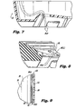
- Fig. 7 is a partial cross-section view of the lower support rim of the protective jacket of the pressure vessel shown in Fig. 5;
- Fig. 8 is a partial cross-section view of the padding and lower support rim of the pressure vessel shown in Fig. 5;
- Fig. 9 is a partial cross-section view of an protective jacket and hybrid tank of the assembled pressure vessel shown in Fig. 1, showing the channel for flow of air between the hybrid tank and the protective jacket;
- Fig. 10 is a partial cut away perspective view of the pressure vessel shown in Fig. 1, showing how the flow of air can pass trough the openings in the upper support rim and into the space between the hybrid tank and the protective jacket;
- Fig. 11 is a partial cross-section view of the assembled pressure vessel shown in Fig. 2, showing how the flow of air can pass trough the openings in the lower support rim, past the padding, and into the space between the hybrid tank and the protective jacket;
- Fig. 12 is a side view showing two pressure vessels as depicted in Fig. 1 in a nested configuration
- the pressure vessels presented herein, and the products of the methods presented herein, may be used for storing pressurized fluids.
- the present invention is particularly suited for storing and dispensing pressurized fluids while facilitating stacking and portability of the pressure vessel.
- a pressure vessel constructed in accordance with the present invention is suitable for applications including, but not limited to, storing propane, refrigerant gas, and liquids or gases at low or high pressure.
- a pressure vessel including a hybrid tank having an inner liner and an outer reinforcing layer, and a protective jacket adapted to surround the hybrid tank.
- the protective jacket includes an upper support rim having an opening therethrough and a lower support rim having a second opening therethrough.
- the protective jacket also includes a substantially cylindrical wall spaced apart from the hybrid tank to allow a convective flow between the protective jacket and the hybrid tank for convective heat transfer between the pressure vessel and the environment to reduce pressure loss during consumption of the pressurized contents.
- a view of an exemplary embodiment of a pressure vessel made in accordance with the present invention is depicted in Fig. 1 and is designated generally by reference number 10.
- Other aspects of the pressure vessel depicted in Fig. 1 are depicted in Figs. 2-12, as will be described.
- a pressure vessel 10 is provided with a hybrid tank 14.
- Hybrid tank 14 has a tank liner 38 that may be formed from a generally cylindrical tube 20 and first and second dome-shaped, semi-hemispherical endcaps 22 and 24.
- Endcaps 22 and 24 may be of any size or shape, such as frustro-conical or flattened, and may be identical or different.
- First and second endcaps 22 and 24 are secured to first and second end rims 26 and 28 of tube 20, respectively, which may be accomplished by any conventional welding techniques known in the art, such as laser welding.
- Tube 20 and first and second endcaps 22 and 24 cooperate to define vessel storage cavity 30, as particularly depicted in Figs. 6 and 9.
- first endcap 22 includes a central aperture 32 defined therein for receiving a valve boss 34, which is secured to aperture 32 by any conventional welding or other suitable joining techniques as are known in the art.
- Valve boss 34 is configured to receive a valve fitting assembly 36 therein, and the combination permits the ingress or egress of fluids to vessel storage cavity 30.
- the tank liner 38 may be constructed without the tube 20.
- endcaps 22 and 24 are joined directly to each other rather than to the tube 20.
- endcaps 22, 24 may take on a variety of shapes, and need not be generally hemispherical, but can be more "cup" shaped, as desired, as will be appreciated by those of skill in the art.
- tank liner 38 including tube 20, first and second endcaps 22 and 24, and valve boss 34 are constructed of an inert, impermeable and non-corrosive material having a high modulus of elasticity, such as 10 million psi or greater, and a low elastic strain generally ranging from about 0.05% to about 1%.
- the tank liner 38 and valve fitting assembly 36 may be made from steel, but may also be fabricated of metals such as, but not limited to, aluminum, nickel, titanium, platinum, or any other material which would provide suitable structural support in accordance with the present invention. It is also within the scope and spirit of the invention to fabricate the tank liner 38 from polymeric materials.
- a hybrid tank is further provided including an outer reinforcing layer.
- a cross section of a wall section of hybrid tank 14 is depicted.
- an outer reinforcing layer 42 is disposed about the tank liner 38.
- Reinforcing layer 42 is fabricated of one or more layers of a material having a higher elastic strain limit than that of the material used for the tank liner 38, as described in further detail below.
- an anti-corrosive coating 40 is applied to the outside of the tank liner 38 before disposing the reinforcing layer 42 on the tank liner. This can be particularly advantageous where the tank liner 38 is fabricated from metal.
- the anti-corrosive coating 40 helps prevent corrosion between the tank liner 38 and the reinforcing layer 42, which could otherwise weaken the hybrid tank 14.
- the anticorrosive coating can be composed of a variety of materials, including zinc rich primers and other anti-corrosive coatings as are known in the art.
- the anti-corrosive coating can be applied, for example, by spraying a powder coating on the tank liner 38, followed by heating to set the power coat. Other methods of applying the anti-corrosive coating are also possible and within the scope of the invention.
- the anti-corrosive coating 40 is applied to the entire outward surface of the tank liner 38.
- Reinforcing layer 42 may include a composite material having a skeleton that imparts desirable mechanical properties to the composite, such as a high tensile strength, and a matrix of material having high ductility that can bind the composite to render it stiff and rigid, among other things. Reinforcing layer 42 reinforces and provides impact resistance to hybrid tank 14.
- the outer surface of reinforcing layer 42 preferably includes a protective layer 44 comprised of a gel coating, for example or other finishing coatings to protect the reinforcing layer 42.
- Suitable materials for forming protective layer 44 include, for example, thermoplastic modified polyolefin powder, applied, for example, by spraying techniques and consequent heating to set, and the like.
- the composite material in reinforcing layer 42 consists of fibers or filaments that are commingled or impregnated with a thermoplastic resin.
- the impregnated filaments may include, but are not limited to, combinations of glass, metal, aramid, carbon, graphite, boron, synthetics, resins, epoxies, polyamides, polyoelfins, silicones, and polyurethanes, among other things.
- the filaments are a composite of thermoplastic resin, such as vinyl epoxy or polypropylene, and glass fiber.
- the filaments can be formed from a commingled thermoplastic and glass fiber fabric sold as TWINTEX, commercially available from Saint-Gobain Vetrotex America Inc.
- the composite material used in reinforcing layer 42 is a recyclable material.
- the pressure vessel includes a protective jacket.
- protective jacket 12 surrounds the hybrid tank 14.
- Protective jacket 12 has a substantially flat circular upper support rim 46, and a substantially flat circular lower support rim 50, and a substantially cylindrical wall 54 between the upper support rim 46 and lower support rim 50.
- Upper support rim 46 is disposed substantially about the periphery of an upper portion 48 of the hybrid tank 14 and a lower support rim 50 is disposed substantially about the periphery of a lower portion 52 of the hybrid tank 14.
- Figs. 1 and 3 depict upper airflow openings 16 in the upper support rim 46.
- Upper airflow openings 16 and lower airflow openings 18 allow air to flow to and from outside to facilitate heat transfer between the environment and the pressurized contents of the hybrid tank 14, discussed in detail below.
- Upper and lower support rims 46 and 50 are preferably configured to engage the hybrid tank 14 to restrict movement of the hybrid tank 14 within the confines of protective jacket 12. Movement is further restricted by the shock absorbing padding 56 in the lower support rim 50 disposed between protective jacket 12 and hybrid tank 14.
- Padding 56 can be made from a variety of materials, including expanded polypropylene, among others.
- Protective jacket 12 is preferably constructed of a rigid, lightweight material, such as a hard plastic, such as polypropylene or high density polyethylene, or other suitable materials. In this configuration, the protective jacket 12 can protect the hybrid tank 14 from impacts, abrasions, and exposure to corrosive materials, among other things.
- the configuration of protective jacket 12 permits for enhanced flow that may substantially surround the circumference of the hybrid tank 14. This is an advance over the art because heat exchange takes place along a greater surface area than allowed for in the wave-like channels known in the art. This enhancement to the flow and surface area of the convective heat exchange helps compensate for the increased thermal insulation of the hybrid tank 14 as contrasted with the all-metal tanks of the prior art.
- the present invention facilitates downward natural convective flows between the protective jacket 12 and the hybrid tank 14 to gain the advantages of the protective jacket while minimizing the loss of pressure due to inadequate heat exchange.
- the substantially cylindrical wall 54 of protective jacket 12 is disposed around a middle portion 51 of hybrid tank 14. As shown in Fig. 9, the inner surface of the substantially cylindrical wall 54 is spaced apart from the outer surface of the hybrid tank 14 to allow a generally downward vertical flow of air to develop between the hybrid tank 14 and the protective jacket 12. There is thus a generally annular flow channel 58 defined between the hybrid tank 14 and the protective jacket 12 in fluid communication with the environment in which the pressure vessel 10 is located.
- Fig. 10 shows how air can communicate from outside the pressure vessel 10, through the upper openings 16, down into the annular flow channel 58 and out through lower openings 18.
- Figs. 7, 8, and 11 show how air can communicate from the substantially annular flow channel 58 inside the pressure vessel 10, past openings 18(a) in the padding 56 (Fig. 5), through the lower openings 18, and into the environment.
- the ability of air to flow from upper openings 16, through the annular flow channel 58, and out the lower openings 18 permits natural convection flows to develop along the whole circumference of the annular flow channel 58, and thus gives the pressure vessel an enhanced ability to exchange heat between the hybrid tank 14 and the environment, while also having the added durability afforded by the protective jacket 12.
- the upper support rim 46 includes a pair of opposed, arcuate handles 60 configured to permit access to valve fitting assembly 36, as shown in Figs. 1-3.
- handle 60 is ergonomically designed to assist transport of pressure vessel 10.
- handle 60 and lower support rim 50 are preferably configured to engage one another to facilitate transporting and stacking a plurality of pressure vessels 10.
- handles 60 are curved and configured to form a non-permanent mating engagement with lower support rim 50, which is configured to receive the handles 60, when stacking multiple pressure vessels 10.
- a pressure vessel can be provided further including a means for uniquely identifying each tank.
- an identification means such as a radio frequency identification tag, microchip and/or barcode 200 (Fig. 1) can be provided to uniquely identify each pressure vessel.
- a database can be maintained for uniquely identifying and tracking each cylinder after the cylinder leaves the manufacturing facility. A variety of variables can be tracked for each cylinder by the manufacturer, such as the tare weight, retest date, manufacturing date, batch or lot numbers, and the like.
- a method for manufacturing a pressure vessel preferably includes forming a tank liner (such as tank liner 38), heating glass filaments, commingling the filaments with a thermoplastic material, winding the thermoplastic material and commingled filaments onto the tank liner 38 under application of heat to form a hybrid tank 14, and attaching a protective jacket 12 to the hybrid tank 14 to create the substantially annular flow channel 58 as described herein.
- the method can further include a step of applying an anti-corrosion coating to the outside of the tank liner 38 before winding the thermoplastic material and commingled filaments onto the tank liner 38.
- This anti-corrosion coating 40 can reduce corrosion between the tank liner 38 and outer reinforcing layer 42 in the case of a metal tank liner 38.
- the winding step can include rotating the tank liner on a mandrel while the filaments are wound onto the tank liner, as is known in the art.
- the winding may be done continuously with a single filament comprising the outer reinforcing layer 42 of hybrid tank 14.
- the method may further include applying a final outer gel coating 44 over the outer reinforcing layer 42, as is known in the art.
- the protective jacket 12 it is possible for the protective jacket 12 to be attached to the hybrid tank 14 by having the protective jacket be separable into at least two sections that attach together with clipping systems as is known in the art.
- the sections can be separable along a circumference of the generally cylindrical wall 54 of protective jacket 54, as shown in Fig. 5. Or the sections could be separable longitudinally or obliquely without departing from the spirit and scope of the invention.
- the sections of the jacket may be attached to one another by permanent or non-permanent engagement, as desired.
- the sections of jacket 12 may be permanently attached to each other by welding, adhesive or fasteners.
- the connection between sections of jacket 12 may be non-permanent, such as by a snap fit connection.
Landscapes
- Engineering & Computer Science (AREA)
- Mechanical Engineering (AREA)
- General Engineering & Computer Science (AREA)
- Filling Or Discharging Of Gas Storage Vessels (AREA)
- Moulding By Coating Moulds (AREA)
Applications Claiming Priority (1)
| Application Number | Priority Date | Filing Date | Title |
|---|---|---|---|
| US11/540,189 US7699188B2 (en) | 2004-04-23 | 2006-09-29 | Hybrid pressure vessel with separable jacket |
Publications (3)
| Publication Number | Publication Date |
|---|---|
| EP1906076A2 true EP1906076A2 (de) | 2008-04-02 |
| EP1906076A3 EP1906076A3 (de) | 2018-03-07 |
| EP1906076B1 EP1906076B1 (de) | 2020-09-09 |
Family
ID=38596630
Family Applications (2)
| Application Number | Title | Priority Date | Filing Date |
|---|---|---|---|
| EP07011698.3A Active EP1906075B1 (de) | 2006-09-29 | 2007-06-14 | Hybriddruckbehälter mit trennbarem Mantel |
| EP07013924.1A Active EP1906076B1 (de) | 2006-09-29 | 2007-07-17 | Schutzschicht für ein Druckgefäß |
Family Applications Before (1)
| Application Number | Title | Priority Date | Filing Date |
|---|---|---|---|
| EP07011698.3A Active EP1906075B1 (de) | 2006-09-29 | 2007-06-14 | Hybriddruckbehälter mit trennbarem Mantel |
Country Status (12)
| Country | Link |
|---|---|
| US (2) | US7699188B2 (de) |
| EP (2) | EP1906075B1 (de) |
| KR (1) | KR100892102B1 (de) |
| AU (2) | AU2007202759B8 (de) |
| BR (1) | BRPI0702533B1 (de) |
| CA (1) | CA2664782C (de) |
| CR (1) | CR10754A (de) |
| ES (2) | ES2829381T3 (de) |
| MX (1) | MX2008013795A (de) |
| NZ (1) | NZ555873A (de) |
| PT (2) | PT1906075T (de) |
| WO (1) | WO2008042321A1 (de) |
Families Citing this family (42)
| Publication number | Priority date | Publication date | Assignee | Title |
|---|---|---|---|---|
| US20110147390A1 (en) * | 2004-04-23 | 2011-06-23 | Amtrol Licensing Inc. | Hybrid pressure vessels for high pressure applications |
| US20110168726A1 (en) * | 2004-04-23 | 2011-07-14 | Amtrol Licensing Inc. | Hybrid pressure vessels for high pressure applications |
| EP2283273A4 (de) * | 2008-05-08 | 2017-12-27 | AMTROL Licensing Inc. | Ständer für druckbehälter |
| US8215517B2 (en) * | 2008-12-17 | 2012-07-10 | Amtrol Licensing, Inc. | Compressed gas cylinder having conductive polymeric foot ring |
| WO2010144917A2 (en) * | 2009-06-12 | 2010-12-16 | Arysta Lifescience North America, Llc | A reusable tote for hazardous chemicals |
| GB0922355D0 (en) * | 2009-12-21 | 2010-02-03 | Linde Ag | Pressure vessel |
| US20110210130A1 (en) * | 2010-03-01 | 2011-09-01 | Jason Ontjes | Decorative propane tank assembly |
| US20110210029A1 (en) * | 2010-03-01 | 2011-09-01 | Jason Ontjes | Decorative propane tank assembly |
| JP5314629B2 (ja) * | 2010-03-30 | 2013-10-16 | 八千代工業株式会社 | 圧力容器 |
| FR2963820B1 (fr) * | 2010-08-12 | 2014-02-28 | Air Liquide | Reservoir composite et procede de fabrication |
| PT2625455T (pt) * | 2010-10-04 | 2022-01-06 | Amtrol Licensing Inc | Montante de suporte para vaso de pressão |
| US8661644B2 (en) | 2010-10-06 | 2014-03-04 | The Boeing Company | Method and device for forming joints in composite structures |
| US8875931B2 (en) | 2010-11-19 | 2014-11-04 | The Boeing Company | Composite sandwich shell edge joint |
| US8784596B2 (en) | 2010-11-19 | 2014-07-22 | The Boeing Company | Method for making and joining composite sandwich shell edge joint |
| BRPI1102874B1 (pt) * | 2011-06-22 | 2021-12-07 | Somma Technology Engenharia Ltda | Conjunto de anéis de alça e de base substituíveis para um reservatório pressurizado e reservatório pressurizado |
| GB201120518D0 (en) * | 2011-11-28 | 2012-01-11 | Linde Ag | Demountable connecting device |
| JP2014081014A (ja) * | 2012-10-15 | 2014-05-08 | Honda Motor Co Ltd | 圧力ガス容器およびこれを備える車両 |
| US9774047B2 (en) * | 2013-03-26 | 2017-09-26 | GM Global Technology Operations LLC | Method and apparatus for forming a matrix liner for a pressure vessel |
| FR3005040A1 (fr) * | 2013-04-30 | 2014-10-31 | Inguran Llc Dba Sexing Technologies | Dispositif de transport et/ou de stockage comprenant une ampoule isolante a double paroi |
| USD759785S1 (en) * | 2014-09-30 | 2016-06-21 | Hexagon Ragasco As | Gas container |
| US10088102B2 (en) | 2016-03-07 | 2018-10-02 | Amtrol Licensing Inc. | Shroud assembly for a portable pressurized gas cylinder |
| USD812186S1 (en) | 2016-04-28 | 2018-03-06 | Amtrol Licensing Inc. | Portable gas tank shroud |
| US10724684B2 (en) | 2016-09-20 | 2020-07-28 | Amtrol Licensing Inc. | Fiberwound tanks |
| US10514129B2 (en) | 2016-12-02 | 2019-12-24 | Amtrol Licensing Inc. | Hybrid tanks |
| JP6601379B2 (ja) | 2016-12-06 | 2019-11-06 | トヨタ自動車株式会社 | 圧力容器および圧力容器の製造方法 |
| USD845435S1 (en) | 2017-08-23 | 2019-04-09 | Amtrol Licensing, Inc. | Gas cylinder |
| US10627052B2 (en) | 2017-09-01 | 2020-04-21 | Steady Fill Co., LLC | Pressure vessel transport system |
| DE102017215754A1 (de) * | 2017-09-07 | 2019-03-07 | Robert Bosch Gmbh | Tank mit einem Innenbehälter und einer Außenhülle sowie Verfahren zur Herstellung des Tanks |
| USD920466S1 (en) * | 2018-09-27 | 2021-05-25 | Hexagon Ragasco As | Gas container |
| UA129085C2 (uk) | 2018-10-24 | 2025-01-08 | Емтрол Лайсенсінг, Інк. | Напірна ємність з пластиковим вкладишем |
| US11473733B2 (en) * | 2019-02-27 | 2022-10-18 | Amtrol Licensing Inc. | Foot for a portable pressurized gas cylinder |
| US11320206B2 (en) | 2019-10-04 | 2022-05-03 | Hamilton Sundstrand Corporation | Pressure vessel with barrier layer |
| USD931979S1 (en) * | 2019-10-23 | 2021-09-28 | Amtrol Licensing, Inc. | Cylinder |
| JP7196871B2 (ja) * | 2020-02-19 | 2022-12-27 | トヨタ自動車株式会社 | 高圧タンク |
| ES1281261Y (es) * | 2021-09-30 | 2022-01-31 | Saiz Manuel Munoz | Sistema de transporte de energía e hidrógeno |
| EP4286741A1 (de) * | 2021-01-29 | 2023-12-06 | Manuel Muñoz Saiz | Wasserstofftransportsystem |
| KR20230077541A (ko) * | 2021-11-25 | 2023-06-01 | 롯데케미칼 주식회사 | 내충격 보강부재를 구비한 고압용기 |
| USD1055212S1 (en) * | 2022-07-25 | 2024-12-24 | Amtrol Licensing Inc. | Handle |
| USD1064179S1 (en) | 2022-08-05 | 2025-02-25 | Amtrol Licensing Inc. | Cylinder stand |
| KR102861908B1 (ko) * | 2022-12-16 | 2025-09-22 | 주식회사 성우하이텍 | 압력 용기의 제조방법 |
| US20240288128A1 (en) * | 2023-02-26 | 2024-08-29 | Kyle Brown | Pressure relief system, pressure safety device and tool, pressurized container system, processes, and method of use |
| US12398924B1 (en) | 2023-08-25 | 2025-08-26 | John Darcy Bolton | Modular reversible water heater design |
Family Cites Families (45)
| Publication number | Priority date | Publication date | Assignee | Title |
|---|---|---|---|---|
| US549418A (en) * | 1895-11-05 | Ambrose webster woodward | ||
| US1517978A (en) * | 1922-09-08 | 1924-12-02 | Barney J Giese | Jacketed can |
| US3815773A (en) * | 1971-05-17 | 1974-06-11 | Brunswick Corp | Cyclic pressure vessel |
| US3788511A (en) * | 1971-08-16 | 1974-01-29 | R Marsh | Protective jacket and base for pressure vessel |
| US3843010A (en) | 1971-10-13 | 1974-10-22 | Brunswick Corp | Metal lined pressure vessel |
| FR2387414A1 (fr) | 1977-04-15 | 1978-11-10 | Air Liquide | Recipient leger pour le stockage de fluides sous pression |
| US4360116A (en) | 1980-12-08 | 1982-11-23 | Brunswick Corporation | Partially split external barrier for composite structures |
| IT1169999B (it) | 1983-12-14 | 1987-06-03 | Belleli Spa | Procedimento per la realizzazione di un recipiente a pressione con rivestimento anticorrosione e recipiente cosi' ottenuto |
| US4653663A (en) | 1985-10-09 | 1987-03-31 | Dayco Products, Inc. | Clamping assembly for securing a flexible liner to a storage tank, and method therefor |
| SE452284B (sv) | 1986-03-10 | 1987-11-23 | Saab Composite Ab | Tryckkerl av kompositmaterial med i lindningen infogade gavelstycken |
| CA1326832C (fr) | 1987-07-21 | 1994-02-08 | Claude Leon Hembert | Reservoir de fluide et son procede de fabrication |
| SE463834B (sv) | 1988-03-15 | 1991-01-28 | Asea Plast Ab | Tryckkaerl |
| US5253778A (en) | 1992-01-28 | 1993-10-19 | Edo Canada Ltd. | Fluid pressure vessel boss-liner attachment system |
| US5494188A (en) | 1992-01-28 | 1996-02-27 | Edo Canada Ltd. | Fluid pressure vessel boss-liner attachment system with liner/exterior mechanism direct coupling |
| FR2694066B1 (fr) | 1992-07-23 | 1994-10-07 | Aerospatiale | Récipient pour le stockage de fluide sous pression, à rupture sans fragmentation. |
| US5287988A (en) * | 1993-02-03 | 1994-02-22 | Brunswick Corporation | Metal-lined pressure vessel |
| FR2707369B1 (fr) * | 1993-07-09 | 1995-09-08 | Schneider Ind | Réservoir, en particulier, du type bouteille à gaz. |
| US5476189A (en) | 1993-12-03 | 1995-12-19 | Duvall; Paul F. | Pressure vessel with damage mitigating system |
| US5518141A (en) | 1994-01-24 | 1996-05-21 | Newhouse; Norman L. | Pressure vessel with system to prevent liner separation |
| EP0666450A1 (de) | 1994-01-31 | 1995-08-09 | Urenco Deutschland GmbH | Druckbehälter |
| US5673794A (en) | 1995-06-05 | 1997-10-07 | Lucent Technologies Inc. | Constraining sleeve device for stabilizing battery casing contour |
| JPH0996399A (ja) | 1995-07-25 | 1997-04-08 | Toyoda Gosei Co Ltd | 圧力容器 |
| ATE265651T1 (de) | 1995-11-08 | 2004-05-15 | Advanced Lightweight Constructions Group Bv | Druckbestandiger behalter |
| US5822838A (en) | 1996-02-01 | 1998-10-20 | Lockheed Martin Corporation | High performance, thin metal lined, composite overwrapped pressure vessel |
| GB9611018D0 (en) * | 1996-05-25 | 1996-07-31 | Nullifire Ltd | Fire protection container |
| US6022435A (en) | 1996-10-23 | 2000-02-08 | Titan Technologies (Usa), Inc. | Method of making a double wall storage tank having an outer jacket bonded around an aperture |
| NO306226B1 (no) * | 1997-01-31 | 1999-10-04 | Raufoss Composites As | Trykkbeholder |
| US6012411A (en) | 1997-07-25 | 2000-01-11 | Hochbrueckner; Kenneth | Propane tank cover |
| US6015065A (en) | 1997-08-29 | 2000-01-18 | Mcalister; Roy E. | Compact fluid storage system |
| US6135308A (en) | 1998-06-26 | 2000-10-24 | Industrial Technology Research Institute | Boss for a filament wound pressure vessel |
| JP2000046296A (ja) | 1998-07-27 | 2000-02-18 | Kobe Steel Ltd | プラスチックライナー型frp圧力容器 |
| JP4392070B2 (ja) | 1999-01-28 | 2009-12-24 | 高圧ガス保安協会 | 耐衝撃性に優れたfrp圧力容器とその製造方法および、耐衝撃性に優れたfrp圧力容器用保護容器 |
| US6460721B2 (en) | 1999-03-23 | 2002-10-08 | Exxonmobil Upstream Research Company | Systems and methods for producing and storing pressurized liquefied natural gas |
| NO309667B1 (no) | 1999-04-29 | 2001-03-05 | Raufoss Composites As | Fremgangsmate for fremstilling av en trykkbeholder |
| US6189723B1 (en) * | 1999-05-10 | 2001-02-20 | Gary R. Davis | Composite laminated transport container for liquids |
| NL1014290C2 (nl) | 2000-02-04 | 2001-08-07 | Advanced Lightweight Const Gro | Vezelversterkt drukvat en werkwijze voor het maken van een vezelversterkt drukvat. |
| US6386384B1 (en) | 2000-02-09 | 2002-05-14 | Amtrol, Inc. | Full jacket gas cylinder |
| CA2318005A1 (en) | 2000-09-12 | 2002-03-12 | Heinz Portmann | Pre-stressed fibre-reinforce high pressure vessel |
| RU2205330C1 (ru) | 2001-10-04 | 2003-05-27 | Тадтаев Владимир Ираклиевич | Композитный баллон высокого давления и способ его изготовления |
| WO2003031860A1 (en) | 2001-10-12 | 2003-04-17 | Polymer & Steel Technologies Holding Company, L.L.C. | Composite pressure vessel assembly and method |
| US7201383B2 (en) | 2003-04-22 | 2007-04-10 | Gibby Daniel K | Carrier for gas and liquid cylinders |
| US8079408B2 (en) * | 2003-09-22 | 2011-12-20 | Bosch Rexroth Corporation | Pressure vessel assembly for integrated pressurized fluid system |
| WO2005071306A1 (en) * | 2004-01-23 | 2005-08-04 | Sergei Glebovich Koldybaev | Container with transparent liner and semitransparent wall |
| BRPI0510010B1 (pt) * | 2004-04-23 | 2018-07-31 | Amtrol Licensing Inc. | Vaso de pressão com camisa de proteção |
| TR200502731A2 (tr) * | 2005-07-13 | 2007-02-21 | Aygaz Anoni̇m Şi̇rketi̇ | Bir tüp. |
-
2006
- 2006-09-29 US US11/540,189 patent/US7699188B2/en active Active
-
2007
- 2007-06-01 BR BRPI0702533-5A patent/BRPI0702533B1/pt not_active IP Right Cessation
- 2007-06-14 NZ NZ555873A patent/NZ555873A/en not_active IP Right Cessation
- 2007-06-14 ES ES07011698T patent/ES2829381T3/es active Active
- 2007-06-14 PT PT70116983T patent/PT1906075T/pt unknown
- 2007-06-14 AU AU2007202759A patent/AU2007202759B8/en not_active Ceased
- 2007-06-14 EP EP07011698.3A patent/EP1906075B1/de active Active
- 2007-07-06 KR KR1020070068026A patent/KR100892102B1/ko active Active
- 2007-07-17 ES ES07013924T patent/ES2878998T3/es active Active
- 2007-07-17 PT PT70139241T patent/PT1906076T/pt unknown
- 2007-07-17 EP EP07013924.1A patent/EP1906076B1/de active Active
- 2007-10-01 WO PCT/US2007/021056 patent/WO2008042321A1/en not_active Ceased
- 2007-10-01 CA CA2664782A patent/CA2664782C/en active Active
- 2007-10-01 MX MX2008013795A patent/MX2008013795A/es active IP Right Grant
-
2009
- 2009-04-29 CR CR10754A patent/CR10754A/es unknown
-
2010
- 2010-04-16 US US12/761,955 patent/US7935206B2/en active Active
- 2010-06-03 AU AU2010202304A patent/AU2010202304B2/en not_active Ceased
Also Published As
| Publication number | Publication date |
|---|---|
| WO2008042321A1 (en) | 2008-04-10 |
| AU2007202759A8 (en) | 2010-05-13 |
| MX2008013795A (es) | 2008-11-14 |
| US20100236051A1 (en) | 2010-09-23 |
| AU2007202759B8 (en) | 2010-05-13 |
| US7935206B2 (en) | 2011-05-03 |
| EP1906075B1 (de) | 2020-08-05 |
| AU2007202759A1 (en) | 2008-04-17 |
| ES2829381T3 (es) | 2021-05-31 |
| EP1906076A3 (de) | 2018-03-07 |
| EP1906075A2 (de) | 2008-04-02 |
| AU2010202304A1 (en) | 2010-06-24 |
| PT1906076T (pt) | 2020-11-03 |
| EP1906075A3 (de) | 2018-07-11 |
| ES2878998T3 (es) | 2021-11-19 |
| KR100892102B1 (ko) | 2009-04-08 |
| AU2010202304B2 (en) | 2014-01-23 |
| CR10754A (es) | 2009-06-23 |
| CA2664782A1 (en) | 2008-04-10 |
| PT1906075T (pt) | 2020-08-26 |
| KR20080029763A (ko) | 2008-04-03 |
| EP1906076B1 (de) | 2020-09-09 |
| CA2664782C (en) | 2015-06-23 |
| AU2007202759B2 (en) | 2010-04-15 |
| US7699188B2 (en) | 2010-04-20 |
| BRPI0702533A (pt) | 2008-06-03 |
| NZ555873A (en) | 2008-02-29 |
| US20070068957A1 (en) | 2007-03-29 |
| BRPI0702533B1 (pt) | 2020-01-07 |
Similar Documents
| Publication | Publication Date | Title |
|---|---|---|
| EP1906076B1 (de) | Schutzschicht für ein Druckgefäß | |
| US20110168726A1 (en) | Hybrid pressure vessels for high pressure applications | |
| US20110147390A1 (en) | Hybrid pressure vessels for high pressure applications | |
| US7255245B2 (en) | Hybrid pressure vessel with separable jacket | |
| EP3870889B1 (de) | Hybrider druckbehälter mit kunststoffauskleidung |
Legal Events
| Date | Code | Title | Description |
|---|---|---|---|
| PUAI | Public reference made under article 153(3) epc to a published international application that has entered the european phase |
Free format text: ORIGINAL CODE: 0009012 |
|
| AK | Designated contracting states |
Kind code of ref document: A2 Designated state(s): AT BE BG CH CY CZ DE DK EE ES FI FR GB GR HU IE IS IT LI LT LU LV MC MT NL PL PT RO SE SI SK TR |
|
| AX | Request for extension of the european patent |
Extension state: AL BA HR MK YU |
|
| PUAL | Search report despatched |
Free format text: ORIGINAL CODE: 0009013 |
|
| AK | Designated contracting states |
Kind code of ref document: A3 Designated state(s): AT BE BG CH CY CZ DE DK EE ES FI FR GB GR HU IE IS IT LI LT LU LV MC MT NL PL PT RO SE SI SK TR |
|
| AX | Request for extension of the european patent |
Extension state: AL BA HR MK RS |
|
| RIC1 | Information provided on ipc code assigned before grant |
Ipc: F17C 13/00 20060101AFI20180129BHEP Ipc: F17C 13/08 20060101ALI20180129BHEP |
|
| STAA | Information on the status of an ep patent application or granted ep patent |
Free format text: STATUS: REQUEST FOR EXAMINATION WAS MADE |
|
| RAP1 | Party data changed (applicant data changed or rights of an application transferred) |
Owner name: AMTROL LICENSING INC. |
|
| 17P | Request for examination filed |
Effective date: 20180830 |
|
| RBV | Designated contracting states (corrected) |
Designated state(s): AT BE BG CH CY CZ DE DK EE ES FI FR GB GR HU IE IS IT LI LT LU LV MC MT NL PL PT RO SE SI SK TR |
|
| AKX | Designation fees paid |
Designated state(s): AT BE BG CH CY CZ DE DK EE ES FI FR GB GR HU IE IS IT LI LT LU LV MC MT NL PL PT RO SE SI SK TR |
|
| AXX | Extension fees paid |
Extension state: RS Extension state: MK Extension state: HR Extension state: BA Extension state: AL |
|
| GRAJ | Information related to disapproval of communication of intention to grant by the applicant or resumption of examination proceedings by the epo deleted |
Free format text: ORIGINAL CODE: EPIDOSDIGR1 |
|
| STAA | Information on the status of an ep patent application or granted ep patent |
Free format text: STATUS: GRANT OF PATENT IS INTENDED |
|
| GRAP | Despatch of communication of intention to grant a patent |
Free format text: ORIGINAL CODE: EPIDOSNIGR1 |
|
| INTG | Intention to grant announced |
Effective date: 20200305 |
|
| GRAS | Grant fee paid |
Free format text: ORIGINAL CODE: EPIDOSNIGR3 |
|
| GRAA | (expected) grant |
Free format text: ORIGINAL CODE: 0009210 |
|
| STAA | Information on the status of an ep patent application or granted ep patent |
Free format text: STATUS: THE PATENT HAS BEEN GRANTED |
|
| AK | Designated contracting states |
Kind code of ref document: B1 Designated state(s): AT BE BG CH CY CZ DE DK EE ES FI FR GB GR HU IE IS IT LI LT LU LV MC MT NL PL PT RO SE SI SK TR |
|
| REG | Reference to a national code |
Ref country code: GB Ref legal event code: FG4D |
|
| REG | Reference to a national code |
Ref country code: AT Ref legal event code: REF Ref document number: 1312007 Country of ref document: AT Kind code of ref document: T Effective date: 20200915 Ref country code: CH Ref legal event code: EP |
|
| REG | Reference to a national code |
Ref country code: IE Ref legal event code: FG4D |
|
| REG | Reference to a national code |
Ref country code: DE Ref legal event code: R096 Ref document number: 602007060618 Country of ref document: DE |
|
| REG | Reference to a national code |
Ref country code: PT Ref legal event code: SC4A Ref document number: 1906076 Country of ref document: PT Date of ref document: 20201103 Kind code of ref document: T Free format text: AVAILABILITY OF NATIONAL TRANSLATION Effective date: 20201026 |
|
| REG | Reference to a national code |
Ref country code: LT Ref legal event code: MG4D |
|
| PG25 | Lapsed in a contracting state [announced via postgrant information from national office to epo] |
Ref country code: GR Free format text: LAPSE BECAUSE OF FAILURE TO SUBMIT A TRANSLATION OF THE DESCRIPTION OR TO PAY THE FEE WITHIN THE PRESCRIBED TIME-LIMIT Effective date: 20201210 Ref country code: LT Free format text: LAPSE BECAUSE OF FAILURE TO SUBMIT A TRANSLATION OF THE DESCRIPTION OR TO PAY THE FEE WITHIN THE PRESCRIBED TIME-LIMIT Effective date: 20200909 Ref country code: FI Free format text: LAPSE BECAUSE OF FAILURE TO SUBMIT A TRANSLATION OF THE DESCRIPTION OR TO PAY THE FEE WITHIN THE PRESCRIBED TIME-LIMIT Effective date: 20200909 Ref country code: BG Free format text: LAPSE BECAUSE OF FAILURE TO SUBMIT A TRANSLATION OF THE DESCRIPTION OR TO PAY THE FEE WITHIN THE PRESCRIBED TIME-LIMIT Effective date: 20201209 Ref country code: SE Free format text: LAPSE BECAUSE OF FAILURE TO SUBMIT A TRANSLATION OF THE DESCRIPTION OR TO PAY THE FEE WITHIN THE PRESCRIBED TIME-LIMIT Effective date: 20200909 |
|
| REG | Reference to a national code |
Ref country code: AT Ref legal event code: MK05 Ref document number: 1312007 Country of ref document: AT Kind code of ref document: T Effective date: 20200909 |
|
| REG | Reference to a national code |
Ref country code: NL Ref legal event code: MP Effective date: 20200909 |
|
| PG25 | Lapsed in a contracting state [announced via postgrant information from national office to epo] |
Ref country code: LV Free format text: LAPSE BECAUSE OF FAILURE TO SUBMIT A TRANSLATION OF THE DESCRIPTION OR TO PAY THE FEE WITHIN THE PRESCRIBED TIME-LIMIT Effective date: 20200909 |
|
| PG25 | Lapsed in a contracting state [announced via postgrant information from national office to epo] |
Ref country code: CZ Free format text: LAPSE BECAUSE OF FAILURE TO SUBMIT A TRANSLATION OF THE DESCRIPTION OR TO PAY THE FEE WITHIN THE PRESCRIBED TIME-LIMIT Effective date: 20200909 Ref country code: EE Free format text: LAPSE BECAUSE OF FAILURE TO SUBMIT A TRANSLATION OF THE DESCRIPTION OR TO PAY THE FEE WITHIN THE PRESCRIBED TIME-LIMIT Effective date: 20200909 Ref country code: RO Free format text: LAPSE BECAUSE OF FAILURE TO SUBMIT A TRANSLATION OF THE DESCRIPTION OR TO PAY THE FEE WITHIN THE PRESCRIBED TIME-LIMIT Effective date: 20200909 Ref country code: NL Free format text: LAPSE BECAUSE OF FAILURE TO SUBMIT A TRANSLATION OF THE DESCRIPTION OR TO PAY THE FEE WITHIN THE PRESCRIBED TIME-LIMIT Effective date: 20200909 |
|
| PG25 | Lapsed in a contracting state [announced via postgrant information from national office to epo] |
Ref country code: AT Free format text: LAPSE BECAUSE OF FAILURE TO SUBMIT A TRANSLATION OF THE DESCRIPTION OR TO PAY THE FEE WITHIN THE PRESCRIBED TIME-LIMIT Effective date: 20200909 Ref country code: IS Free format text: LAPSE BECAUSE OF FAILURE TO SUBMIT A TRANSLATION OF THE DESCRIPTION OR TO PAY THE FEE WITHIN THE PRESCRIBED TIME-LIMIT Effective date: 20210109 |
|
| REG | Reference to a national code |
Ref country code: DE Ref legal event code: R097 Ref document number: 602007060618 Country of ref document: DE |
|
| PG25 | Lapsed in a contracting state [announced via postgrant information from national office to epo] |
Ref country code: SK Free format text: LAPSE BECAUSE OF FAILURE TO SUBMIT A TRANSLATION OF THE DESCRIPTION OR TO PAY THE FEE WITHIN THE PRESCRIBED TIME-LIMIT Effective date: 20200909 |
|
| PLBE | No opposition filed within time limit |
Free format text: ORIGINAL CODE: 0009261 |
|
| STAA | Information on the status of an ep patent application or granted ep patent |
Free format text: STATUS: NO OPPOSITION FILED WITHIN TIME LIMIT |
|
| 26N | No opposition filed |
Effective date: 20210610 |
|
| PG25 | Lapsed in a contracting state [announced via postgrant information from national office to epo] |
Ref country code: DK Free format text: LAPSE BECAUSE OF FAILURE TO SUBMIT A TRANSLATION OF THE DESCRIPTION OR TO PAY THE FEE WITHIN THE PRESCRIBED TIME-LIMIT Effective date: 20200909 Ref country code: SI Free format text: LAPSE BECAUSE OF FAILURE TO SUBMIT A TRANSLATION OF THE DESCRIPTION OR TO PAY THE FEE WITHIN THE PRESCRIBED TIME-LIMIT Effective date: 20200909 |
|
| PGFP | Annual fee paid to national office [announced via postgrant information from national office to epo] |
Ref country code: IT Payment date: 20210730 Year of fee payment: 15 |
|
| REG | Reference to a national code |
Ref country code: ES Ref legal event code: FG2A Ref document number: 2878998 Country of ref document: ES Kind code of ref document: T3 Effective date: 20211119 |
|
| REG | Reference to a national code |
Ref country code: CH Ref legal event code: PL |
|
| PG25 | Lapsed in a contracting state [announced via postgrant information from national office to epo] |
Ref country code: MC Free format text: LAPSE BECAUSE OF FAILURE TO SUBMIT A TRANSLATION OF THE DESCRIPTION OR TO PAY THE FEE WITHIN THE PRESCRIBED TIME-LIMIT Effective date: 20200909 |
|
| REG | Reference to a national code |
Ref country code: BE Ref legal event code: MM Effective date: 20210731 |
|
| PG25 | Lapsed in a contracting state [announced via postgrant information from national office to epo] |
Ref country code: LI Free format text: LAPSE BECAUSE OF NON-PAYMENT OF DUE FEES Effective date: 20210731 Ref country code: CH Free format text: LAPSE BECAUSE OF NON-PAYMENT OF DUE FEES Effective date: 20210731 |
|
| PG25 | Lapsed in a contracting state [announced via postgrant information from national office to epo] |
Ref country code: LU Free format text: LAPSE BECAUSE OF NON-PAYMENT OF DUE FEES Effective date: 20210717 |
|
| PG25 | Lapsed in a contracting state [announced via postgrant information from national office to epo] |
Ref country code: IE Free format text: LAPSE BECAUSE OF NON-PAYMENT OF DUE FEES Effective date: 20210717 Ref country code: BE Free format text: LAPSE BECAUSE OF NON-PAYMENT OF DUE FEES Effective date: 20210731 |
|
| PG25 | Lapsed in a contracting state [announced via postgrant information from national office to epo] |
Ref country code: HU Free format text: LAPSE BECAUSE OF FAILURE TO SUBMIT A TRANSLATION OF THE DESCRIPTION OR TO PAY THE FEE WITHIN THE PRESCRIBED TIME-LIMIT; INVALID AB INITIO Effective date: 20070717 Ref country code: CY Free format text: LAPSE BECAUSE OF FAILURE TO SUBMIT A TRANSLATION OF THE DESCRIPTION OR TO PAY THE FEE WITHIN THE PRESCRIBED TIME-LIMIT Effective date: 20200909 |
|
| PG25 | Lapsed in a contracting state [announced via postgrant information from national office to epo] |
Ref country code: IT Free format text: LAPSE BECAUSE OF NON-PAYMENT OF DUE FEES Effective date: 20220717 |
|
| PG25 | Lapsed in a contracting state [announced via postgrant information from national office to epo] |
Ref country code: MT Free format text: LAPSE BECAUSE OF FAILURE TO SUBMIT A TRANSLATION OF THE DESCRIPTION OR TO PAY THE FEE WITHIN THE PRESCRIBED TIME-LIMIT Effective date: 20200909 |
|
| PGFP | Annual fee paid to national office [announced via postgrant information from national office to epo] |
Ref country code: DE Payment date: 20240725 Year of fee payment: 18 |
|
| PGFP | Annual fee paid to national office [announced via postgrant information from national office to epo] |
Ref country code: GB Payment date: 20240723 Year of fee payment: 18 |
|
| PGFP | Annual fee paid to national office [announced via postgrant information from national office to epo] |
Ref country code: FR Payment date: 20240724 Year of fee payment: 18 |
|
| PGFP | Annual fee paid to national office [announced via postgrant information from national office to epo] |
Ref country code: ES Payment date: 20250819 Year of fee payment: 19 Ref country code: PT Payment date: 20250731 Year of fee payment: 19 |
|
| PGFP | Annual fee paid to national office [announced via postgrant information from national office to epo] |
Ref country code: PL Payment date: 20250801 Year of fee payment: 19 Ref country code: TR Payment date: 20250807 Year of fee payment: 19 |
|
| REG | Reference to a national code |
Ref country code: DE Ref legal event code: R119 Ref document number: 602007060618 Country of ref document: DE |
|
| GBPC | Gb: european patent ceased through non-payment of renewal fee |
Effective date: 20250717 |
|
| PG25 | Lapsed in a contracting state [announced via postgrant information from national office to epo] |
Ref country code: GB Free format text: LAPSE BECAUSE OF NON-PAYMENT OF DUE FEES Effective date: 20250717 |
|
| PG25 | Lapsed in a contracting state [announced via postgrant information from national office to epo] |
Ref country code: DE Free format text: LAPSE BECAUSE OF NON-PAYMENT OF DUE FEES Effective date: 20260203 |
|
| PG25 | Lapsed in a contracting state [announced via postgrant information from national office to epo] |
Ref country code: FR Free format text: LAPSE BECAUSE OF NON-PAYMENT OF DUE FEES Effective date: 20250731 |