EP1906097A2 - Cuiseur électrique avec dispositif de refroidissement et son procédé de contrôle - Google Patents
Cuiseur électrique avec dispositif de refroidissement et son procédé de contrôle Download PDFInfo
- Publication number
- EP1906097A2 EP1906097A2 EP07112591A EP07112591A EP1906097A2 EP 1906097 A2 EP1906097 A2 EP 1906097A2 EP 07112591 A EP07112591 A EP 07112591A EP 07112591 A EP07112591 A EP 07112591A EP 1906097 A2 EP1906097 A2 EP 1906097A2
- Authority
- EP
- European Patent Office
- Prior art keywords
- upper panel
- fan
- heating cooker
- fan housing
- cooker according
- Prior art date
- Legal status (The legal status is an assumption and is not a legal conclusion. Google has not performed a legal analysis and makes no representation as to the accuracy of the status listed.)
- Withdrawn
Links
Images




Classifications
-
- F—MECHANICAL ENGINEERING; LIGHTING; HEATING; WEAPONS; BLASTING
- F24—HEATING; RANGES; VENTILATING
- F24C—DOMESTIC STOVES OR RANGES ; DETAILS OF DOMESTIC STOVES OR RANGES, OF GENERAL APPLICATION
- F24C7/00—Stoves or ranges heated by electric energy
- F24C7/08—Arrangement or mounting of control or safety devices
-
- F—MECHANICAL ENGINEERING; LIGHTING; HEATING; WEAPONS; BLASTING
- F24—HEATING; RANGES; VENTILATING
- F24C—DOMESTIC STOVES OR RANGES ; DETAILS OF DOMESTIC STOVES OR RANGES, OF GENERAL APPLICATION
- F24C15/00—Details
- F24C15/10—Tops, e.g. hot plates; Rings
- F24C15/101—Tops, e.g. hot plates; Rings provisions for circulation of air
-
- F—MECHANICAL ENGINEERING; LIGHTING; HEATING; WEAPONS; BLASTING
- F24—HEATING; RANGES; VENTILATING
- F24C—DOMESTIC STOVES OR RANGES ; DETAILS OF DOMESTIC STOVES OR RANGES, OF GENERAL APPLICATION
- F24C7/00—Stoves or ranges heated by electric energy
- F24C7/04—Stoves or ranges heated by electric energy with heat radiated directly from the heating element
Definitions
- the present invention relates to a heating cooker and a method of controlling the same, and, more particularly, to a heating cooker which can forcibly cool a surface of an upper panel on which a cooking container is laid, and a method of controlling the same.
- heating cookers can be classified into gas cooking devices that heat food or cooking containers with gas combustion heat, and electric cooking devices that heat the food or the cooking containers with electric energy.
- electric cooking devices there are an electrothermal cooker which directly heats the food or the cooking containers by use of heat generated from an electrothermal body, an induction heating cooker which heats the cooking container by use of eddy currents, a microwave oven which heats the food via penetration of microwaves generated from super high frequency oscillator into the food, etc.
- multi-functional cookers which can perform various cooking operations, such as roasting, frying, steaming, boiling, thawing, etc.
- Such multi-functional cookers include a gas oven, an electrical oven, and a combination oven which employs both gas and electricity.
- the multi-functional cooker has several cooking units to allow various cooking operations.
- the electrical microwave oven includes a cooking chamber to receive cooking containers or food and to heat the cooking containers and food evenly throughout, and an upper panel having a heater disposed thereon to heat the cooking container.
- a cook-top type heating cooker is disclosed as an example of the electrical microwave oven in U.S. Patent Publication No. 2003-0029858, published February 13, 2003 , and includes an upper panel and a temperature sensor positioned under the upper panel.
- a heater is positioned near the temperature sensor under an upper panel made from a ceramic material.
- the heater includes a heating conductor which is supplied with power to generate heat, and the temperature sensor detects the heating temperature in preparation for control of the power supplied to the heating conductor.
- the heating conductor generates heat through application of power thereto, the cooking container laid on the surface of the upper panel is heated to perform the cooking operation.
- Such a conventional heating cooker has a problem in that, since the upper panel remains heated for a long period of time after the cooking operation and the application of the power to the heating conductor are finished, there can be an accident caused by carelessness of a user.
- the conventional heating cooker is provided at an exterior with an alarm light such that, if the upper panel has a predetermined temperature or more even after the heater is turned off, the alarm light is lit, thus warning the user.
- a heating cooker which can forcibly cool a heated upper panel after a cooking operation to reduce or remove likelihood of an accident, such as burns caused by carelessness of a user, and a method of controlling the same.
- a heating cooker including: a body constituting an appearance of the heating cooker; an upper panel on which a cooking container may be laid; a heater positioned under the upper panel to heat the cooking container laid on the upper panel; and a surface cooling device to cool the upper panel.
- the surface cooling device may include a blast fan to forcibly blow air toward a surface of the upper panel, and a fan motor to operate the blast fan.
- the surface cooling device may further include a fan housing to receive the blast fan and the fan motor, the fan housing being liftably positioned at one side of the body to be raised above the upper panel and being formed with an air discharge port through which air blown by the blast fan is discharged toward the surface of the upper panel.
- the fan housing may be provided with a blow guide to guide the air blown by the blast fan to descend toward the surface of the upper panel.
- the heating cooker may further include a fan housing lifter to raise and lower the fan housing.
- the fan housing lifter may include a rack positioned at one side of the fan housing, a pinion engaged with the rack, and a motor to rotate the pinion.
- the heating cooker may further include an emission duct positioned at the other side of the body to guide the air discharged from the fan housing and flowing on the upper panel, the emission duct including an air inlet through which the air flowing on the upper panel enters the emission duct and an air outlet through which the air induced through the air inlet is emitted.
- the emission duct may be liftably attached to the body to allow the air inlet to be raised above the upper panel.
- the heating cooker may further include an emission duct lifter to raise and lower the emission duct.
- the emission duct lifter may include a rack positioned at one side of the emission duct, a pinion engaged with the rack, and a motor to rotate the pinion.
- a heating cooker including: a body constituting an appearance of the heating cooker; an upper panel on which a cooking container may be laid; a heater positioned under the upper panel to heat the cooking container laid on the upper panel; a surface cooling device to cool the upper panel; and a controller to control the heater and the surface cooling device.
- the heating cooker may further include a temperature sensor to detect a temperature of the upper panel, the controller controlling the surface cooling device in response to signals from the temperature sensor.
- a method of controlling a heating cooker including raising a fan housing having a blast fan and a fan motor received therein above an upper panel when a heater positioned under the upper panel is turned off after completion of a cooking operation; driving the fan motor to blow air toward the upper panel; and stopping the fan motor when the upper panel is cooled, followed by retracting the fan housing to its original position.
- the method may further include detecting a temperature of the upper panel, and the stopping of the fan motor followed by the retracting of the fan housing may be performed when the detected temperature is lower than a predetermined temperature.
- the stopping of the fan motor followed by the retracting of the fan housing may be performed with an elapse of a predetermined time after the driving of the fan motor.
- a heating cooker including an upper panel; at least one heater positioned beneath the upper panel; at least one temperature sensor detecting a temperature of a portion of the upper panel; and a liftably retractable surface cooling device cooling the upper panel.
- FIG. 1 is a perspective view of a heating cooker according to a first embodiment of the invention
- FIG. 2 is a block diagram showing components of the heating cooker
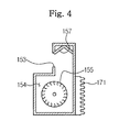
- FIGS. 3 and 4 are a front view and a side sectional view showing a major component of the heating cooker
- FIG. 5 is a front view illustrating operation of the heating cooker
- FIG. 6 is a flow chart illustrating a method of controlling the heating cooker according to a first embodiment of the invention.
- the heating cooker 100 includes a body 110 constituting an appearance thereof, an upper panel 120 on the body 110, a plurality of heaters 130 under the upper panel 120, a surface cooling device 140 liftably positioned at both sides of the body 110, and a controller 180 to control the heating cooker 100.
- the body 110 is provided at a front side with a door 111, and at one side of an upper portion with a control panel 112.
- the body 110 has a cooking chamber (not shown) which is defined to receive a cooking container or food therein and is opened and closed by the door 111.
- the control panel 112 may include various operation switches 113 for a user's manipulation, and a display window 114 to show the state of the heating cooker 100.
- An installation space is defined between the cooking chamber and either side of the body 110.
- the upper panel 120 may be made of a ceramic material.
- a plurality of surface heating parts 121 on which the cooking container can be laid.
- Each of the heaters 130 is located under a corresponding surface heating part 121 to heat the surface heating part 121.
- the corresponding heater 130 may be operated to heat the cooking container and perform the cooking operation.
- the plural heaters 130 are positioned under the respective surface heating parts 121 and heat the corresponding surface heating parts 121.
- the heaters 130 may be radiant heaters, halogen heaters, or any other type of heating device.
- the surface cooling device 140 serves to forcibly cool the upper panel 120 heated by any of the heaters 130 after completing the cooking operation.
- the surface cooling device 140 includes a fan housing 151 and an emission duct 161 liftably positioned at either side of the body 110 to protrude above the upper panel 120.
- the fan housing 151 has an air intake port 152 through which air is sucked into the fan housing 151, and an air discharge port 153 (shown in FIG. 3) through which the air is discharged from the fan housing 151.
- the air intake port 152 is formed at either side of the fan housing 151 as shown in FIG. 1, and the air discharge port 153 is formed at an upper front side of the fan housing 151 as shown in FIGS. 3 and 4.
- a blowing chamber 154 is defined in the fan housing 151, and is installed therein with a blast fan 155 to forcibly blow air and a fan motor 156 to drive the blast fan 155.
- the fan housing 151 is provided at an inside upper portion with a blow guide 157 to guide air blown by the blast fan 155 toward the air discharge port 153.
- the blow guide 157 is bent to have gentle slopes, and disposed longitudinally along the air discharge port 153.
- the blow guide 157 serves to change a flow direction of the air blown from the blowing chamber 154 and to guide the air discharged through the air discharge port 153 to be directed downward.
- the air discharge port 153 is directed to the surface of the upper panel 120. Then, as the blast fan 155 is actuated, air is sucked into the blowing chamber 154 through the air intake port 152, flows toward the blow guide 157 from the blowing chamber 154, and is then discharged toward the surface of the upper panel 120 through the air discharge port 153 along the blow guide 157.
- the fan housing lifter 171 raises and lowers the fan housing 151 above and below the upper panel 120.
- the fan housing lifter 171 includes a rack 172 positioned at a rear of the fan housing 151, a pinion 173 engaging with the rack 172, and a first motor 174 to drive the pinion 173.
- the rack 172 is forced upward or downward to raise or lower the fan housing 151.
- the first motor 174 is controlled by the controller 180.
- the emission duct 161 is liftably positioned opposite the fan housing 151 with the upper panel 120 disposed therebetween.
- the emission duct 161 has an air inlet 162 through which air discharged from the fan housing 151 and then flowing past the surface of the upper panel 120 is induced into the emission duct 161, and an air outlet 163 through which the air induced into the emission duct 161 is emitted to the outside.
- the air inlet 162 has an elongated shape formed at an upper portion of the emission duct 161 to face the air discharge port 153 of the fan housing 151, and the air outlet 163 is positioned at either side of the emission duct 161 to allow the air to be emitted in front and rear directions of the body 110.
- the emission duct 161 is raised above the upper panel 120 along with the fan housing 151, and then guides the air, which is discharged from the fan housing 151 and then flows past the surface of the upper panel 120, into the body 110.
- the air outlet 163 may be formed at other locations, such as lower portions of the emission duct 161, rather than either side of the emission duct 161, to emit the air towards other portions within the body 110.
- an emission duct lifter 175 includes a rack 176 positioned at the rear of the emission duct 161, a pinion 177 engaging with the rack 176, and a second motor 178 to drive the pinion 177.
- the rack 176 is forced upward or downward to raise or lower the emission duct 161.
- the second motor 178 is controlled by the controller 180.
- the controller 180 controls the first and second motors 174 and 178, the fan motor 156, the heater 130, and the display window 114 in response to signals from the operation switches 113 and temperature sensors 190.
- the temperature sensors 190 are positioned proximate the respective heaters 130 under the upper panel 120 to detect the temperature of the upper panel 120 heated by the heaters 130.
- the surface cooling device 140 can be manually or automatically actuated.
- the surface cooling device 140 may be actuated by manipulating a separated actuation switch able to be manipulated by a user, or may be automatically actuated by the controller 180 after the cooking operation. Cessation of the cooling by the surface cooling device 140 is automatically performed in response to a detection signal via the temperature sensor 190 when the temperature of the upper panel 120 is lowered to or less than a predetermined degree.
- the fan housing lifter 171 and the emission duct lifter 175 that raise and lower the fan housing 151 and the emission duct 161 commonly employ various linear movement devices, such as cams, links, ball screws, worm gears, etc., as well as using the rack and pinion.
- a corresponding heater 130 With a cooking container laid on the surface heating part 121 of the upper panel 120, a corresponding heater 130 (see FIG. 1) is turned on (S10) to heat the surface heating part 121, performing a cooking operation. With an elapse of time after the heater 130 is turned on, the controller 180 (see FIG. 2) determines whether or not the heater is turned off (S20). If it is determined that the heater is not turned off, the routine returns to S20 until the heater is determined to be turned off. If it is determined that the heater 130 is turned off by completion of the cooking operation, the controller 180 actuates the first and second motors 174 and 178 for a predetermined period of time to raise the fan housing 151 and the emission duct 161 above the upper panel 120 (S30).
- the air discharge port 153 of the fan housing 151 and the air inlet 162 of the emission duct 161 are positioned above the surface of the upper panel 120 and face each other with the upper panel 120 disposed therebetween.
- the controller 180 drives the fan motor 156 (see FIG. 3) to rotate the blast fan 155 (S40). As the blast fan 155 is rotated, air flows along the blow guide 157 from the blowing chamber 154, and is discharged downwardly through the air discharge port 153.
- the air discharge port 153 After being discharged through the air discharge port 153, the air flows past the surface of the upper panel 120 toward the emission duct 161 while cooling the upper panel 120 heated by the heater 130. Then, the air is induced into the emission duct 161 through the air inlet 162 of the emission duct 161, and discharged to the outside through the air outlet 163 thereof.
- the controller 180 While the air discharged from the fan housing 151 cools the upper panel 120, the controller 180 detects a temperature T of the upper panel 120 by use of an associated temperature sensor 190 (S50), and determines whether the temperature T is lower than a predetermined temperature Ts (S60). Here, it is desirable that the predetermined temperature be sufficiently low to prevent a user from being burned. If the detected temperature T is not lower than the predetermined temperature Ts, the routine returns to S60 until the temperature T is detected to be lower than the predetermined temperature Ts.
- the controller 180 stops the fan motor 156 (S70), and actuates the first and second motors 174 and 178 for a predetermined period of time to descend the fan housing 151 and the emission duct 161 to their original positions (S80).
- position detection sensors may be respectively positioned near the fan housing 151 and the emission duct 161 to detect raised positions of the fan housing 151 and the emission duct 161.
- the controller 180 controls the first and second motors 174 and 178 in response to signals from the position detection sensors.
- the controller 180 may return the fan housing 151 and the emission duct 161 to their original positions after raising the fan housing 151 and the emission duct 161 and operating the fan motor 156 for a predetermined period of time.
- the operating time of the fan motor 156 may be determined through experiment so as to allow the upper panel 120 to be sufficiently cooled by the blown air.
- a heating cooker 200 according to a second embodiment of the invention is schematically shown in a front view.
- the heating cooker 200 according to this embodiment has a similar configuration to that of the above embodiment except that a surface cooling device 240 is constituted without using the emission duct.
- the heating cooker 200 includes a body 210, an upper panel 120 (see FIG. 1), a plurality of heaters 130 (see FIG. 1), a surface cooling device 240, a plurality of temperature sensors 190 (see FIG. 1), and a controller 180 (see FIG. 2).
- the surface cooling device 240 includes a fan housing 251 liftably positioned at one side of the body 210, a blast fan 155 (see FIG. 3) and a fan motor 156 (see FIG. 3) positioned in the fan housing 251, and a fan housing lifter 271 to raise or lower the fan housing 251.
- the fan housing 271 includes a rack 272, a pinion 273, and a motor 274.
- the fan housing 251 When the cooking operation is finished, the fan housing 251 is raised above the upper panel 120, and blows air over the surface of the upper panel 120. Then, the air flows past the surface of the upper panel 120 toward an opposite side of the fan housing 251 while cooling the upper panel 120.
- the fan housing 151 is raised above the upper panel 120 before the upper panel is cooled to a suitable temperature, making the user more cautious about the heated upper panel 120.
Landscapes
- Engineering & Computer Science (AREA)
- Chemical & Material Sciences (AREA)
- Combustion & Propulsion (AREA)
- Mechanical Engineering (AREA)
- General Engineering & Computer Science (AREA)
- Electric Stoves And Ranges (AREA)
Applications Claiming Priority (1)
| Application Number | Priority Date | Filing Date | Title |
|---|---|---|---|
| KR1020060090296A KR20080025603A (ko) | 2006-09-18 | 2006-09-18 | 가열조리기 및 그 제어방법 |
Publications (1)
| Publication Number | Publication Date |
|---|---|
| EP1906097A2 true EP1906097A2 (fr) | 2008-04-02 |
Family
ID=38705152
Family Applications (1)
| Application Number | Title | Priority Date | Filing Date |
|---|---|---|---|
| EP07112591A Withdrawn EP1906097A2 (fr) | 2006-09-18 | 2007-07-17 | Cuiseur électrique avec dispositif de refroidissement et son procédé de contrôle |
Country Status (4)
| Country | Link |
|---|---|
| US (1) | US20080067167A1 (fr) |
| EP (1) | EP1906097A2 (fr) |
| KR (1) | KR20080025603A (fr) |
| CN (1) | CN101147653A (fr) |
Cited By (2)
| Publication number | Priority date | Publication date | Assignee | Title |
|---|---|---|---|---|
| CN101558959B (zh) * | 2009-05-27 | 2010-11-17 | 陈俊喜 | 全自动早餐机 |
| EP3490337A1 (fr) * | 2017-11-22 | 2019-05-29 | Vestel Elektronik Sanayi ve Ticaret A.S. | Appareil de chauffage |
Families Citing this family (19)
| Publication number | Priority date | Publication date | Assignee | Title |
|---|---|---|---|---|
| TW201200997A (en) * | 2010-06-28 | 2012-01-01 | Hon Hai Prec Ind Co Ltd | System and method for cooling a fan of an electronic device |
| DE102012200384B4 (de) * | 2011-12-29 | 2018-03-15 | Continental Automotive Gmbh | Auf einem Träger angeordnete Schaltungsanordnung mit Temperaturüberwachung und Verfahren zum Erkennen einer Übertemperatur |
| CN103371739B (zh) * | 2012-04-13 | 2016-09-21 | 美的集团股份有限公司 | 一种煎烤机 |
| US9578694B2 (en) | 2014-06-20 | 2017-02-21 | Haier U.S. Appliance Solutions, Inc. | Ventilation systems and methods for operating the same |
| ES2957934T3 (es) * | 2014-06-23 | 2024-01-30 | Ember Tech Inc | Vajilla y cristalería caliente o fría |
| CN104391527B (zh) * | 2014-11-10 | 2017-02-15 | 广东美的厨房电器制造有限公司 | 冷却组件和电器 |
| KR101642098B1 (ko) * | 2014-12-23 | 2016-07-22 | 주식회사 엔씨엠 | 전기레인지의 잔열 관리장치 |
| KR102305832B1 (ko) | 2015-01-05 | 2021-09-28 | 삼성전자주식회사 | 가스오븐 |
| CN104825049B (zh) * | 2015-05-18 | 2017-09-26 | 广东美的厨房电器制造有限公司 | 电蒸炉 |
| CN104983294B (zh) * | 2015-06-29 | 2018-10-12 | 中宁县智才技术服务有限公司 | 自动烹饪设备 |
| CN109945253A (zh) * | 2017-12-20 | 2019-06-28 | 华帝股份有限公司 | 用于电磁灶面板的散热机构及其电磁灶 |
| KR102580371B1 (ko) * | 2017-12-29 | 2023-09-19 | 코웨이 주식회사 | 조절 가능한 포집부를 포함하는 전열 조리장치 |
| KR102025277B1 (ko) * | 2018-04-13 | 2019-09-25 | 이선재 | 조리용 순간 스팀발생기 |
| US10948193B2 (en) | 2018-08-06 | 2021-03-16 | Haier Us Appliance Solutions, Inc. | Fan assembly for an induction cooking appliance |
| JP7629001B2 (ja) * | 2019-08-07 | 2025-02-12 | エーエヌエイチ イノベーション, インコーポレイテッド | プレナム及びディフューザー付き可動式再循環グリル |
| KR102839017B1 (ko) * | 2020-08-31 | 2025-07-25 | 엘지전자 주식회사 | 주방용 후드 |
| CN116868008A (zh) * | 2021-05-11 | 2023-10-10 | 三星电子株式会社 | 烹饪设备及其控制方法 |
| EP4269878B1 (fr) * | 2021-05-11 | 2025-08-13 | Samsung Electronics Co., Ltd. | Appareil de cuisson et son procédé de commande |
| WO2022239949A1 (fr) * | 2021-05-11 | 2022-11-17 | 삼성전자주식회사 | Appareil de cuisson et son procédé de commande |
Family Cites Families (8)
| Publication number | Priority date | Publication date | Assignee | Title |
|---|---|---|---|---|
| US3409005A (en) * | 1966-12-19 | 1968-11-05 | Jenn Air Corp | Cooking range with retractable ventilating flue |
| FR2635852B1 (fr) * | 1988-08-29 | 1994-09-16 | Samsung Electronics Co Ltd | Appareil electronique de cuisson du type modulaire |
| US4934337A (en) * | 1989-10-02 | 1990-06-19 | General Electric Company | Retractable vent and cover arrangement for down draft cooking appliance |
| US5408073A (en) * | 1993-02-20 | 1995-04-18 | Samsung Electronics Co., Ltd. | Overheat prevention circuit for electromagnetic induction heating cooker |
| EP0675672A1 (fr) * | 1994-03-31 | 1995-10-04 | Superluck Electrics Corp. | Dispositif de radiation de chaleur pour élément chauffant par induction |
| IT1292485B1 (it) * | 1997-07-04 | 1999-02-08 | Whirlpool Co | Sistema di ventilazione per apparecchi elettrici di cottura di alimenti comprendenti un piano di cottura e un forno |
| DE10006956A1 (de) * | 2000-02-16 | 2001-08-23 | Bsh Bosch Siemens Hausgeraete | Kochfeld mit Temperaturfühler |
| DE10122427A1 (de) * | 2001-05-09 | 2002-11-14 | Bsh Bosch Siemens Hausgeraete | Verfahren und Vorrichtung zur Begrenzung und/oder Steuerung der Oberflächentemperatur eines Kochfelds |
-
2006
- 2006-09-18 KR KR1020060090296A patent/KR20080025603A/ko not_active Withdrawn
-
2007
- 2007-07-17 EP EP07112591A patent/EP1906097A2/fr not_active Withdrawn
- 2007-07-17 US US11/826,657 patent/US20080067167A1/en not_active Abandoned
- 2007-07-27 CN CNA2007101383010A patent/CN101147653A/zh active Pending
Cited By (2)
| Publication number | Priority date | Publication date | Assignee | Title |
|---|---|---|---|---|
| CN101558959B (zh) * | 2009-05-27 | 2010-11-17 | 陈俊喜 | 全自动早餐机 |
| EP3490337A1 (fr) * | 2017-11-22 | 2019-05-29 | Vestel Elektronik Sanayi ve Ticaret A.S. | Appareil de chauffage |
Also Published As
| Publication number | Publication date |
|---|---|
| KR20080025603A (ko) | 2008-03-21 |
| CN101147653A (zh) | 2008-03-26 |
| US20080067167A1 (en) | 2008-03-20 |
Similar Documents
| Publication | Publication Date | Title |
|---|---|---|
| EP1906097A2 (fr) | Cuiseur électrique avec dispositif de refroidissement et son procédé de contrôle | |
| KR101617283B1 (ko) | 조리기기 및 그 운전 방법 | |
| US20240230104A1 (en) | Method for cooling the vapor or steam escaping from the cooking chamber of a cooking device, and cooking device | |
| JP6872690B2 (ja) | 加熱調理器 | |
| JP2019020122A (ja) | 加熱調理器 | |
| JP5511957B2 (ja) | 加熱調理器 | |
| CN101375105B (zh) | 高频加热装置 | |
| KR100218961B1 (ko) | 소량 조리물의 과다조리를 방지하는 전자렌지의 제어방법 | |
| KR20010041758A (ko) | 제어 알고리즘이 수동으로 입력되는 컴비네이션 오븐 | |
| JPH09271447A (ja) | オーブン | |
| JP4969351B2 (ja) | 誘導加熱調理器 | |
| JP3913641B2 (ja) | 誘導加熱調理器 | |
| KR100364567B1 (ko) | 요리중오븐도어의냉각방법및그장치 | |
| RU2388970C2 (ru) | Встраиваемое устройство для термообработки продуктов | |
| JP7511528B2 (ja) | 加熱調理器 | |
| KR101516815B1 (ko) | 오븐레인지의 보온 서랍 온도제어장치 및 방법 | |
| KR20060098258A (ko) | 3상 전원을 사용하는 전기 오븐 레인지 | |
| KR100709422B1 (ko) | 텔레스코픽 랙을 채용한 전기오븐레인지 및 그 제어방법 | |
| KR20090078062A (ko) | 조리장치 및 그 안전제어방법 | |
| JP4989165B2 (ja) | 加熱調理器 | |
| KR100562105B1 (ko) | 전기오븐의 도어 락킹 시스템 | |
| JP2004039375A (ja) | 加熱調理器 | |
| KR20250042614A (ko) | 가전기기 및 그 제어방법 | |
| KR20250052190A (ko) | 가전기기 및 그 제어방법 | |
| JP2016110921A (ja) | 誘導加熱調理器 |
Legal Events
| Date | Code | Title | Description |
|---|---|---|---|
| PUAI | Public reference made under article 153(3) epc to a published international application that has entered the european phase |
Free format text: ORIGINAL CODE: 0009012 |
|
| AK | Designated contracting states |
Kind code of ref document: A2 Designated state(s): AT BE BG CH CY CZ DE DK EE ES FI FR GB GR HU IE IS IT LI LT LU LV MC MT NL PL PT RO SE SI SK TR |
|
| AX | Request for extension of the european patent |
Extension state: AL BA HR MK YU |
|
| STAA | Information on the status of an ep patent application or granted ep patent |
Free format text: STATUS: THE APPLICATION IS DEEMED TO BE WITHDRAWN |
|
| 18D | Application deemed to be withdrawn |
Effective date: 20100302 |