EP3490337A1 - Appareil de chauffage - Google Patents
Appareil de chauffage Download PDFInfo
- Publication number
- EP3490337A1 EP3490337A1 EP17203022.3A EP17203022A EP3490337A1 EP 3490337 A1 EP3490337 A1 EP 3490337A1 EP 17203022 A EP17203022 A EP 17203022A EP 3490337 A1 EP3490337 A1 EP 3490337A1
- Authority
- EP
- European Patent Office
- Prior art keywords
- heating element
- heating
- wind
- sensor
- heating appliance
- Prior art date
- Legal status (The legal status is an assumption and is not a legal conclusion. Google has not performed a legal analysis and makes no representation as to the accuracy of the status listed.)
- Withdrawn
Links
- 238000010438 heat treatment Methods 0.000 title claims abstract description 164
- 238000010411 cooking Methods 0.000 claims description 18
- 239000007789 gas Substances 0.000 description 20
- 235000013305 food Nutrition 0.000 description 8
- 230000005611 electricity Effects 0.000 description 4
- 229910052736 halogen Inorganic materials 0.000 description 4
- 150000002367 halogens Chemical class 0.000 description 4
- 230000006698 induction Effects 0.000 description 4
- 239000007788 liquid Substances 0.000 description 4
- 230000008901 benefit Effects 0.000 description 3
- 230000008859 change Effects 0.000 description 3
- 238000013500 data storage Methods 0.000 description 3
- 239000000446 fuel Substances 0.000 description 3
- 238000012545 processing Methods 0.000 description 3
- 239000004065 semiconductor Substances 0.000 description 3
- ATUOYWHBWRKTHZ-UHFFFAOYSA-N Propane Chemical compound CCC ATUOYWHBWRKTHZ-UHFFFAOYSA-N 0.000 description 2
- 238000004590 computer program Methods 0.000 description 2
- 238000001816 cooling Methods 0.000 description 2
- VNWKTOKETHGBQD-UHFFFAOYSA-N methane Chemical compound C VNWKTOKETHGBQD-UHFFFAOYSA-N 0.000 description 2
- 238000000034 method Methods 0.000 description 2
- 230000008569 process Effects 0.000 description 2
- 239000004215 Carbon black (E152) Substances 0.000 description 1
- 235000021168 barbecue Nutrition 0.000 description 1
- 239000001273 butane Substances 0.000 description 1
- 230000000694 effects Effects 0.000 description 1
- 229930195733 hydrocarbon Natural products 0.000 description 1
- 150000002430 hydrocarbons Chemical class 0.000 description 1
- 238000005259 measurement Methods 0.000 description 1
- 239000002184 metal Substances 0.000 description 1
- 239000000203 mixture Substances 0.000 description 1
- 238000012986 modification Methods 0.000 description 1
- 230000004048 modification Effects 0.000 description 1
- IJDNQMDRQITEOD-UHFFFAOYSA-N n-butane Chemical compound CCCC IJDNQMDRQITEOD-UHFFFAOYSA-N 0.000 description 1
- OFBQJSOFQDEBGM-UHFFFAOYSA-N n-pentane Natural products CCCCC OFBQJSOFQDEBGM-UHFFFAOYSA-N 0.000 description 1
- 239000003345 natural gas Substances 0.000 description 1
- 230000003287 optical effect Effects 0.000 description 1
- 239000001294 propane Substances 0.000 description 1
- 230000009467 reduction Effects 0.000 description 1
- 230000004044 response Effects 0.000 description 1
- 230000000717 retained effect Effects 0.000 description 1
- 238000012546 transfer Methods 0.000 description 1
Images


Classifications
-
- F—MECHANICAL ENGINEERING; LIGHTING; HEATING; WEAPONS; BLASTING
- F24—HEATING; RANGES; VENTILATING
- F24C—DOMESTIC STOVES OR RANGES ; DETAILS OF DOMESTIC STOVES OR RANGES, OF GENERAL APPLICATION
- F24C15/00—Details
- F24C15/28—Draught shields
-
- F—MECHANICAL ENGINEERING; LIGHTING; HEATING; WEAPONS; BLASTING
- F24—HEATING; RANGES; VENTILATING
- F24C—DOMESTIC STOVES OR RANGES ; DETAILS OF DOMESTIC STOVES OR RANGES, OF GENERAL APPLICATION
- F24C3/00—Stoves or ranges for gaseous fuels
- F24C3/12—Arrangement or mounting of control or safety devices
- F24C3/126—Arrangement or mounting of control or safety devices on ranges
-
- H—ELECTRICITY
- H05—ELECTRIC TECHNIQUES NOT OTHERWISE PROVIDED FOR
- H05B—ELECTRIC HEATING; ELECTRIC LIGHT SOURCES NOT OTHERWISE PROVIDED FOR; CIRCUIT ARRANGEMENTS FOR ELECTRIC LIGHT SOURCES, IN GENERAL
- H05B6/00—Heating by electric, magnetic or electromagnetic fields
- H05B6/02—Induction heating
- H05B6/10—Induction heating apparatus, other than furnaces, for specific applications
- H05B6/12—Cooking devices
- H05B6/1209—Cooking devices induction cooking plates or the like and devices to be used in combination with them
Definitions
- the present disclosure relates to a heating appliance.
- Heating appliances are used in many applications for heating items.
- a cooking hob (or a stovetop) is an appliance that may be used to cook or heat food, liquids, etc.
- a cooking hob typically includes one or more heating elements that generate localised heat when activated.
- a pan or other vessel containing food, a liquid, etc. can be placed on an activated heating element in order to cook the food in the pan.
- the heating element of a cooking hob may be, for example, a gas burner, a radiant heating coil, a halogen lamp, an electrical resistive element or a magnetic induction element.
- a heating appliance comprising: a heating element; a sensor configured to detect wind impinging on the heating element; a wind shield at least partially surrounding the heating element, the wind shield comprising a wall; a driving element configured to move the wall between a stowed position and a deployed position; and a controller configured to activate the driving element to move the wall from its stowed position to its deployed position if the controller determines the sensor has detected wind impinging on the heating element.
- the controller allows for the controller to automatically obstruct the flow of wind impinging on a heating element of a heating appliance such as a cooking hob. Impeding the flow of wind in this manner prevents the wind from significantly reducing the effectiveness of the heating element, for example by cooling the heating element and/or by excessive cooling of any cooking vessel (depending on for example the height of the wall(s) once raised).
- the heating element is a gas burner.
- the heating element is a gas burner, moving the wall to its deployed position reduces the likelihood that an ignited gas burner will be extinguished by the wind.
- the heating appliance comprises a plurality of sensors
- the wind shield comprises a plurality of separately movable walls
- the sensors being arranged to be capable of determining the direction of wind impinging on the heating element
- the controller being configured to activate the driving element to move one or more walls according to the direction of wind impinging on the heating element.
- each sensor being associated with one or more of the walls
- the controller being configured to activate the driving element to move the one or more walls associated with a particular sensor from their stowed positions to their deployed positions if the controller determines that the particular sensor has detected wind impinging on the heating element.
- driving element is an electric motor.
- the or each sensor is located on an uppermost surface of the heating appliance.
- the or each sensor is located adjacent the heating element.
- the or each sensor is a temperature sensor.
- the or each temperature sensor is configured to obtain a measure of the temperature of the heating element.
- the controller is configured to move the wall from its stowed position to its deployed position if the controller determines that the temperature sensor has detected a decrease in temperature that is greater than a predetermined threshold value.
- the wind shield fully surrounds the heating element.
- the heating appliance is a cooking hob.
- Heating appliances are used in many applications for heating items.
- a cooking hob (or a stovetop) is an appliance that may be used to cook or heat food, liquids, etc.
- a cooking hob typically includes one or more heating elements that generate localised heat when activated.
- a pan or other vessel containing food, a liquid, etc. can be placed on an activated heating element in order to cook the food in the pan.
- the heating element of a cooking hob may be, for example, a gas burner, a radiant heating coil, a halogen lamp, an electrical resistive element or a magnetic induction element.
- the environment in which a cooking hob is located can reduce the effectiveness of its heating elements. For example, if the environment is windy then the flow of the wind over the heating element may reduce the temperature of the heating element, thus reducing the temperature of the pan. This is frustrating for a user and is particularly a problem when the heating element is a gas burner because wind can extinguish an ignited gas burner.
- a heating appliance 1 in this case a cooking appliance, specifically a cooking hob.
- the heating appliance 1 is a device for use outdoors, such as a barbecue or a grill.
- the heating appliance 1 includes a heating element 2.
- the heating element 2 is a gas burner.
- the heating element may be, for example, a radiant heating coil, a halogen lamp, an electrical resistive element or a magnetic induction element.
- a plurality of heating elements 2 are provided. Specifically, as is shown particularly in Figure 4, four heating elements 2 are provided in this example.
- the heating appliance 1 shown in Figure 1 includes two pan supports 3, which are metal grates that provide a surface above the heating element 2 on which a pan can be rested so that the pan can be heated by the heating element 2.
- pan supports 3 have been removed from the heating appliance 1 in Figures 2 and 3 .
- the heating appliance 1 also provides for a connection (not shown) to a source of fuel to be used by the heating elements 2 to provide heat.
- a source of fuel to be used by the heating elements 2 to provide heat.
- the fuel supplied to the heating appliance 1 is natural gas or a specific hydrocarbon gas or mixture, such as butane and/or propane.
- the heating elements 2 are radiant heating coils, halogen lamps, electrical resistive elements or magnetic induction elements
- the fuel may be electricity.
- the heating appliance 1 also provides for a connection (not shown) to a source of electricity, which is used to ignite the gas and to supply electricity to the other components that are described below.
- the source of electricity may be a mains connection or may be battery. Indeed, the heating appliance may include a battery.
- one or more sensors 4 are provided in the region around a heating element 2.
- the sensors 4 are configured to detect whether wind is impinging on the heating element 2.
- a plurality of sensors 4 is provided in respect of each heating element 2.
- the sensors 4 in this example are each located on an uppermost surface 7 of the heating appliance 1 such that when wind is impinging on the heating element 2, wind is also contacting at least one of the sensors 4.
- the sensors 4 in this example are spaced equidistantly around the heating element 2.
- the sensors 4 may be configured to also detect one or more of: (i) the speed of the wind impinging on the heating element 2 and (ii) the direction of the wind impinging on the heating element 2.
- four sensors 4 are provided around each heating element 2.
- the sensors 4 are adjacent the heating element 2. This arrangement can be used to more precisely detect the direction of wing acting on the heating element 2.
- three sensors 4 are provided around one heating element 2.
- Three sensors 4 is the minimum number of sensors 4 that are required to detect the direction of wind contacting the heating element 2 to a reasonable degree of accuracy. More sensors 4 may be provided per heating element 2 for more precisely determining the direction of the wind. Alternatively, fewer sensors 4 may be provided per heating element 2 in order to reduce costs.
- each of the sensors 4 is a temperature sensor.
- each of the sensors 4 is another type of sensor that can be configured to detect whether wind is impinging on the heating element 2, such as an anemometer.
- a temperature sensor can be easily and effectively used to detect the presence of wind because the temperature detected by a temperature sensor will vary depending on whether or not wind is acting on the temperature sensor. If wind is flowing over a temperature sensor then the wind will cool the surface of the temperature sensor and the measured temperature will therefore be lower than when wind is not flowing over the temperature sensor. Accordingly, in this example, if wind is flowing over the uppermost surface 7 of the heating appliance 1 and thus contacting the heating element 2, the wind will cool the temperature sensor and the resulting measured temperature will be lower than when wind is not contacting with the heating element 2.
- each sensor 4 is in thermal contact with the heating element 2. In another example, each sensor 4 is in direct physical contact with the heating element 2.
- Each temperature sensor may be, for example, a negative temperature coefficient thermistor or a positive temperature coefficient thermistor.
- a measure of the speed of the wind can be obtained based on a temperature detected by a temperature sensor because a higher wind speed correlates to a lower measured temperature.
- a measure of the direction of wind impinging on the heating element 2 can be obtained based on the temperatures detected by the temperature sensors because the temperature sensor(s) that wind is flowing over will detect a lower temperature than other temperature sensors.
- a wind shield 5 at least partially surrounds the heating element 2.
- the heating element 2 is fully surrounded by the wind shield 5.
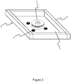
- the wind shield 5 in this example includes a plurality of walls 6 that are each independently movable between a stowed position (shown in Figure 2 ) and a deployed position (shown in Figure 3 ).
- each wind shield 5 includes four walls 6.
- the wind shield 5 may include only one wall 6.
- the walls 6 each comprise a shape that can impede the flow of wind.
- each wall 6 has a cuboid shape. When a wall 6 is in its deployed position, the wall 6 protrudes away from heating appliance 1 so that it is raised above the uppermost surface 7.
- One or more walls 6 may include an indent that receives the pan support 3 when the wall 6 is in its deployed position.
- the wall 6 is housed within the body of the heating appliance 1 such that an uppermost face of the wall 6 is substantially flush with the uppermost surface 7 of the heating appliance 1.
- One or more walls 6 may be associated with one or more sensors 4, or vice versa.
- the heating appliance 1 may include a data storage storing information on the associations between the walls 6 and the sensors 4.
- a wall 6 may be associated with an adjacent sensor 4. Associating a wall 6 with a sensor 4 allows for that specific wall 6 to be moved between its stowed position and its deployed position based on whether a particular sensor 4 detects wind contacting with the heating element 2.
- the heating appliance 1 includes an electrical motor.
- the electrical motor acts as a driving element and is constructed and arranged to drive the walls 6 between their stowed position (see Figure 2 ) and their deployed position (see Figure 3 ).
- the heating appliance 1 may include a different driving element that can drive the walls 6 between their deployed position and their stowed position, such as one or more hydraulic actuators or one or more pneumatic actuators.
- the electrical motor can drive each wall 6 individually and independently between its stowed position and its deployed position, for example by use of appropriate gearing and linkages (not shown). This allows for some walls 6 to be driven to their deployed position and some walls 6 to be retained in their stowed position.
- At least one wall 6 can be left in its stowed position whilst others are in their deployed position, which may make it easier for a user to place a pan on to, or remove a pan from, the heating element 2, whilst the deployed walls 6 still impede the flow of wind impinging on the heating element 2.
- the heating appliance 1 includes a controller, which may be a processor or the like.
- the controller is connected to each sensor 4, the electrical motor and the data storage.
- the controller is configured to move one or more walls 6 from their stowed position to their deployed position when the controller determines that a sensor 4 has detected that wind is impinging on the heating element 2.
- the controller may be configured to move a wall 6 that is associated with a particular sensor 4 from its stowed position to its deployed position when its associated sensor 4 detects that wind is impinging on the heating element 2.
- the controller is configured to move one or more walls 6 from their stowed position to their deployed position when the controller determines that a sensor 4, which is a temperature sensor in this example, has detected a change in temperature that is greater than a predetermined threshold value.
- the heating element 2 of the heating appliance 1 is deactivated and the walls 6 of the wind shield 5 are in their stowed position.
- a user wanting to use the cooking hob to cook or heat food, etc., activates the heating element 2 so that the heating element 2 outputs heat. Since the heating element 2 in this example is a gas burner, a user turns a dial to begin gas flow to the heating element 2 and then ignites the gas flow using, for example, a match.
- the heating element 2 is now activated and is outputting heat.
- a user can now cook food in a pan by placing the pan onto the pan support 3 so that it sits over to the heating element 2.
- the temperature sensors When there is no wind impinging on the heating element 2, the temperature sensors each detect the same temperature (or substantially similar temperatures) because they are each heated equally by the heating element 2 and not cooled by wind. Consequently, based on the measurements made by the sensors 4, the controller determines that there has not been a change in the temperature detected by a sensor 4 that is greater than a predetermined threshold value. The controller therefore determines that there is no wind contacting the heating element 2 and thus that the walls 6 of the wind shield 5 should remain in their stowed positions.
- wind begins to contact the heating element 2. If the strength of the wind is sufficient then, since the heating element 2 in this example is a gas burner, the wind may extinguish the ignited gas burner.
- the wind flows over the uppermost surface 7 of the heating appliance 1, over the sensors 4 and into contact with the heating element 2.
- the wind may not flow over a sensor 4 if it is hidden behind the heating element 2 because the heating element 2 may impede the flow of the wind.
- the wind flowing over the sensors 4 reduces the temperature of the surface of at least some of the sensors 4 due to wind chill caused by conduction. This change in temperature is detected by the sensors 4 because the sensors 4 in this example are temperature sensors. The temperature of some of the sensors 4 may be further reduced if the wind is of sufficient strength to blow the flame of the ignited heating element away from these sensors 4.
- the controller determines that at least one of the sensors 4 has detected a reduction in temperature that is more than a predetermined threshold value. Consequently, the controller determines that wind is impinging on the heating element 2.
- the controller activates the electrical motor to drive all of the walls 6 of the wind shield 5 from their stowed position (as shown in Figure 2 ) to their deployed position (as shown in Figure 3 ). The electrical motor maintains the walls 6 in their deployed position until the user has deactivated the heating element 2.
- the walls 6 obstruct the flow of the wind so that the wind does not impinge on the heating element 2.
- An advantage of this is that by eliminating or reducing the flow rate of wind impinging on the heating element 2, the wind can be prevented from lowering the effectiveness of the heating element 2. Indeed, in this example, the wind shield 5 prevents the wind from extinguishing the ignited gas burner.
- each wall 6 is associated with a particular sensor 4 (or vice versa)
- the controller determines that a particular sensor 4 has detected wind impinging on the heating element 2
- the controller activates the electrical motor to drive the wall (or walls) 6 associated with that sensor 4 from its (their) stowed position(s) to its (their) deployed position(s).
- the controller activates the electrical motor to drive the wall (or walls) 6 associated with that wind direction from its (their) stowed position(s) to its (their deployed) position(s).
- the above arrangement therefore automatically impedes the flow of wind impinging on a heating element of a cooking hob. This prevents the wind from significantly reducing the effectiveness of the heating element. Indeed, when the heating element is a gas burner, the arrangement automatically prevents an ignited gas burner from being extinguished by the wind.
- the processor (controller) or processing system or circuitry referred to herein may in practice be provided by a single chip or integrated circuit or plural chips or integrated circuits, optionally provided as a chipset, an application-specific integrated circuit (ASIC), field-programmable gate array (FPGA), digital signal processor (DSP), graphics processing units (GPUs), etc.
- the chip or chips may comprise circuitry (as well as possibly firmware) for embodying at least one or more of a data processor or processors, a digital signal processor or processors, baseband circuitry and radio frequency circuitry, which are configurable so as to operate in accordance with the exemplary embodiments.
- the exemplary embodiments may be implemented at least in part by computer software stored in (non-transitory) memory and executable by the processor, or by hardware, or by a combination of tangibly stored software and hardware (and tangibly stored firmware).
- the invention also extends to computer programs, particularly computer programs on or in a carrier, adapted for putting the invention into practice.
- the program may be in the form of non-transitory source code, object code, a code intermediate source and object code such as in partially compiled form, or in any other non-transitory form suitable for use in the implementation of processes according to the invention.
- the carrier may be any entity or device capable of carrying the program.
- the carrier may comprise a storage medium, such as a solid-state drive
- SSD semiconductor-based RAM
- ROM read-only memory
- magnetic recording medium for example a floppy disk or hard disk
- optical memory devices in general etc.
Landscapes
- Engineering & Computer Science (AREA)
- Chemical & Material Sciences (AREA)
- Combustion & Propulsion (AREA)
- Mechanical Engineering (AREA)
- General Engineering & Computer Science (AREA)
- Physics & Mathematics (AREA)
- Electromagnetism (AREA)
- Electric Stoves And Ranges (AREA)
Priority Applications (2)
| Application Number | Priority Date | Filing Date | Title |
|---|---|---|---|
| EP17203022.3A EP3490337A1 (fr) | 2017-11-22 | 2017-11-22 | Appareil de chauffage |
| TR2017/19162A TR201719162A2 (tr) | 2017-11-22 | 2017-11-29 | Bi̇r isitma ci̇hazi |
Applications Claiming Priority (1)
| Application Number | Priority Date | Filing Date | Title |
|---|---|---|---|
| EP17203022.3A EP3490337A1 (fr) | 2017-11-22 | 2017-11-22 | Appareil de chauffage |
Publications (1)
| Publication Number | Publication Date |
|---|---|
| EP3490337A1 true EP3490337A1 (fr) | 2019-05-29 |
Family
ID=60450476
Family Applications (1)
| Application Number | Title | Priority Date | Filing Date |
|---|---|---|---|
| EP17203022.3A Withdrawn EP3490337A1 (fr) | 2017-11-22 | 2017-11-22 | Appareil de chauffage |
Country Status (2)
| Country | Link |
|---|---|
| EP (1) | EP3490337A1 (fr) |
| TR (1) | TR201719162A2 (fr) |
Citations (5)
| Publication number | Priority date | Publication date | Assignee | Title |
|---|---|---|---|---|
| US5979428A (en) * | 1998-12-31 | 1999-11-09 | Greene, Jr.; George J. | Wind guard attachment for portable gas cookers |
| KR200399921Y1 (ko) * | 2005-08-11 | 2005-11-01 | 권오기 | 휴대용 가스렌지의 바람막이 |
| EP1906097A2 (fr) * | 2006-09-18 | 2008-04-02 | Samsung Electronics Co.,Ltd. | Cuiseur électrique avec dispositif de refroidissement et son procédé de contrôle |
| WO2011030996A1 (fr) * | 2009-09-08 | 2011-03-17 | Kim Jong Man | Cuisinière à gaz comportant un coupe-vent |
| DE202016001283U1 (de) * | 2016-02-27 | 2016-03-18 | Fatih Kutlu | Windschutz für Gaskocher |
-
2017
- 2017-11-22 EP EP17203022.3A patent/EP3490337A1/fr not_active Withdrawn
- 2017-11-29 TR TR2017/19162A patent/TR201719162A2/tr unknown
Patent Citations (5)
| Publication number | Priority date | Publication date | Assignee | Title |
|---|---|---|---|---|
| US5979428A (en) * | 1998-12-31 | 1999-11-09 | Greene, Jr.; George J. | Wind guard attachment for portable gas cookers |
| KR200399921Y1 (ko) * | 2005-08-11 | 2005-11-01 | 권오기 | 휴대용 가스렌지의 바람막이 |
| EP1906097A2 (fr) * | 2006-09-18 | 2008-04-02 | Samsung Electronics Co.,Ltd. | Cuiseur électrique avec dispositif de refroidissement et son procédé de contrôle |
| WO2011030996A1 (fr) * | 2009-09-08 | 2011-03-17 | Kim Jong Man | Cuisinière à gaz comportant un coupe-vent |
| DE202016001283U1 (de) * | 2016-02-27 | 2016-03-18 | Fatih Kutlu | Windschutz für Gaskocher |
Also Published As
| Publication number | Publication date |
|---|---|
| TR201719162A2 (tr) | 2019-06-21 |
Similar Documents
| Publication | Publication Date | Title |
|---|---|---|
| CN102770711B (zh) | 燃气灶 | |
| US10440778B2 (en) | Temperature controlling device for an appliance heating element | |
| CN108567311B (zh) | 一种烹饪器具防干烧方法、装置以及烹饪系统 | |
| CN109792800B (zh) | 厨房器具和烹饪监控方法 | |
| US10584882B2 (en) | Electric cooktop appliance with heat control | |
| CN110726159A (zh) | 加热控制方法、烹饪器具与系统及计算机可读存储介质 | |
| CN102711301B (zh) | 感应加热烹调器 | |
| JP4936814B2 (ja) | 加熱調理器 | |
| JP5286144B2 (ja) | 誘導加熱調理器 | |
| US10757762B2 (en) | Electric cooktop appliance | |
| JP2009295457A (ja) | 誘導加熱調理器 | |
| TWI542257B (zh) | Induction heating cooker | |
| CN110848754A (zh) | 燃气灶的控制方法和燃气灶 | |
| EP3742054A1 (fr) | Appareil de cuisson et procédé de fonctionnement d'un appareil de cuisson | |
| EP3477204A1 (fr) | Appareil de cuisson et procédé de fonctionnement | |
| CN108141924B (zh) | 用于控制属于烹饪设备的热源的方法以及相关烹饪设备 | |
| JP3888208B2 (ja) | 誘導加熱調理器 | |
| JP2017217177A (ja) | 調理容器 | |
| CN204063172U (zh) | 一种电磁炉 | |
| CN105805791B (zh) | 高周波加热装置 | |
| JP5785974B2 (ja) | 加熱調理器 | |
| JP6845615B2 (ja) | ガスコンロ | |
| JP6752509B2 (ja) | 温度検出装置を備えたガスコンロ | |
| JP6877325B2 (ja) | 加熱調理器 | |
| KR100672305B1 (ko) | 전기오븐레인지의 탑버너 제어 방법 |
Legal Events
| Date | Code | Title | Description |
|---|---|---|---|
| PUAI | Public reference made under article 153(3) epc to a published international application that has entered the european phase |
Free format text: ORIGINAL CODE: 0009012 |
|
| STAA | Information on the status of an ep patent application or granted ep patent |
Free format text: STATUS: THE APPLICATION HAS BEEN PUBLISHED |
|
| AK | Designated contracting states |
Kind code of ref document: A1 Designated state(s): AL AT BE BG CH CY CZ DE DK EE ES FI FR GB GR HR HU IE IS IT LI LT LU LV MC MK MT NL NO PL PT RO RS SE SI SK SM TR |
|
| AX | Request for extension of the european patent |
Extension state: BA ME |
|
| STAA | Information on the status of an ep patent application or granted ep patent |
Free format text: STATUS: REQUEST FOR EXAMINATION WAS MADE |
|
| 17P | Request for examination filed |
Effective date: 20191126 |
|
| RBV | Designated contracting states (corrected) |
Designated state(s): AL AT BE BG CH CY CZ DE DK EE ES FI FR GB GR HR HU IE IS IT LI LT LU LV MC MK MT NL NO PL PT RO RS SE SI SK SM TR |
|
| RIC1 | Information provided on ipc code assigned before grant |
Ipc: H05B 6/12 20060101AFI20191218BHEP Ipc: F24C 15/28 20060101ALI20191218BHEP Ipc: F24C 3/12 20060101ALI20191218BHEP |
|
| GRAP | Despatch of communication of intention to grant a patent |
Free format text: ORIGINAL CODE: EPIDOSNIGR1 |
|
| STAA | Information on the status of an ep patent application or granted ep patent |
Free format text: STATUS: GRANT OF PATENT IS INTENDED |
|
| INTG | Intention to grant announced |
Effective date: 20200124 |
|
| RIN1 | Information on inventor provided before grant (corrected) |
Inventor name: TOPCUOGLU, SERDAR Inventor name: TUNAY, ERKAN |
|
| STAA | Information on the status of an ep patent application or granted ep patent |
Free format text: STATUS: THE APPLICATION IS DEEMED TO BE WITHDRAWN |
|
| 18D | Application deemed to be withdrawn |
Effective date: 20200604 |