EP1906128A2 - Dispositif de transfert de chaleur - Google Patents
Dispositif de transfert de chaleur Download PDFInfo
- Publication number
- EP1906128A2 EP1906128A2 EP07024250A EP07024250A EP1906128A2 EP 1906128 A2 EP1906128 A2 EP 1906128A2 EP 07024250 A EP07024250 A EP 07024250A EP 07024250 A EP07024250 A EP 07024250A EP 1906128 A2 EP1906128 A2 EP 1906128A2
- Authority
- EP
- European Patent Office
- Prior art keywords
- hollow tube
- heat
- evaporator
- connecting pipe
- transfer device
- Prior art date
- Legal status (The legal status is an assumption and is not a legal conclusion. Google has not performed a legal analysis and makes no representation as to the accuracy of the status listed.)
- Ceased
Links
Images


Classifications
-
- F—MECHANICAL ENGINEERING; LIGHTING; HEATING; WEAPONS; BLASTING
- F28—HEAT EXCHANGE IN GENERAL
- F28D—HEAT-EXCHANGE APPARATUS, NOT PROVIDED FOR IN ANOTHER SUBCLASS, IN WHICH THE HEAT-EXCHANGE MEDIA DO NOT COME INTO DIRECT CONTACT
- F28D15/00—Heat-exchange apparatus with the intermediate heat-transfer medium in closed tubes passing into or through the conduit walls ; Heat-exchange apparatus employing intermediate heat-transfer medium or bodies
- F28D15/02—Heat-exchange apparatus with the intermediate heat-transfer medium in closed tubes passing into or through the conduit walls ; Heat-exchange apparatus employing intermediate heat-transfer medium or bodies in which the medium condenses and evaporates, e.g. heat pipes
- F28D15/04—Heat-exchange apparatus with the intermediate heat-transfer medium in closed tubes passing into or through the conduit walls ; Heat-exchange apparatus employing intermediate heat-transfer medium or bodies in which the medium condenses and evaporates, e.g. heat pipes with tubes having a capillary structure
- F28D15/043—Heat-exchange apparatus with the intermediate heat-transfer medium in closed tubes passing into or through the conduit walls ; Heat-exchange apparatus employing intermediate heat-transfer medium or bodies in which the medium condenses and evaporates, e.g. heat pipes with tubes having a capillary structure forming loops, e.g. capillary pumped loops
Definitions
- This invention generally relates to a heat transfer device, and more particularly to a heat transfer device to reduce costs, and enhance heat conductivity.
- a radiator will be disposed on the heating element of the electronic device provide a larger area for heat dissipation.
- a cooling fan will be used to provide a cool air current to further dissipate the heat.
- the electronic device can keep within the range of the operational temperature.
- the radiator and the cooling fan are used in the CPU, North Bridge, and graphic chip of the personal computer, which can generate high heat.
- FIG. 1 is a conventional heat transfer device.
- the conventional heat transfer device 100 comprises an evaporator 110, a loop heat pipe 120, and a condenser 130.
- the evaporator 110 comprises a metal tube 112 and a porous core 114.
- the porous core 114 is disposed inside the metal tube 112.
- the evaporator 110 is disposed on the heating device such as CPU.
- the loop heat pipe 120 is connected to the evaporator 110 and has a proper amount of working fluid therein.
- the condenser 130 is disposed on the loop heat pipe 120 to condense the steam in the loop heat pipe to the liquid state.
- the evaporator 110 When the heating device generates high heat, the evaporator 110 will receives the heat and thus the working fluid in the porous core 114 will be heated up and enter into the loop heat pipe 120 and the condenser 130. The condenser 130 then condenses the steam in the loop heat pipe to the liquid state. The capillarity attraction of the porous core 114 will attract the working fluid in the loop heat pipe 120 back to the evaporator 110 and the porous core 114 therein. Hence, this design forms a loop so that the working fluid can flow circularly in the loop heat pipe 120 and transfer the heat generated by the heating device to the condenser 130.
- a heat conducting platform (not shown) is welded at the bottom of the hollow metal tube 112 so that the high heat of a heating device (not shown) can be transferred from the heat conducting platform to the evaporator 110.
- the heat conducting platform can only conduct the heat to the lower part of the evaporator. Hence the heat conductance is too low.
- An object of the present invention is to provide a heat transfer device to transfer the heat out of the heating device in order to effectively dissipate the heat.
- the heat transfer device is easy to manufacture with low cost.
- the present invention provides a heat transfer device for transferring a heating source from a heating device, the heat transfer device at least comprising: an evaporator, the evaporator comprising: a first hollow tube having one open end; a porous core in the first hollow tube; a second hollow tube having one open end in connection with said one open end of the first hollow tube; a heat conductor covering the evaporator, the heat conductor being on the heating device; a connecting pipe having a first end in fluid communication with the other end of said first hollow tube and a second end in fluid communication with the other end of said second hollow tube, the connecting pipe being used for containing a working fluid; and a condenser on the connecting pipe, the heat transfer device being characterized in that said one open end of said second hollow tube is in tenon-mortise connection with said one open end of said first hollow tube.
- the heat conductor comprises a first heat conducting block having a heat conducting tenon; and a second heat conducting block having a mortise corresponding to the tenon, the heat conducting tenon being inserted into the mortise so that the first and second heat conducting blocks cover the evaporator.
- the height of the tenon is smaller than the depth of the mortise to enhance the tightness between the tenon and the mortise so that the first and second heat conducting blocks can contact closely the outer wall of the evaporator to obtain good heat conductivity.
- the porous core has a fluid channel therein, the fluid channel being connected to a fluid reservoir.
- a vapor channel is between the first hollow tube and the porous core, and the vapor channel is connected to the connecting pipe.
- the first hollow tube has a closed end; the closed end has a first surface; the first surface has a first hole; the connecting pipe has an end connected to the first hole to connect the first hollow tube.
- the second hollow tube has a closed end; the closed end has a second surface; the second surface has a second hole; the connecting pipe has an end connected to the second hole to connect the second hollow tube.
- FIG. 1 is a conventional heat transfer device.
- FIG. 2 is the structure of the heat transfer device in accordance with a preferred embodiment of the present invention.
- FIG. 3 is a cross-sectional view of FIG. 5 along the A-A line.
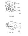
- FIGs. 4A-4D show the structure of the heat conductor device in accordance with another preferred embodiment of the present invention.
- FIG. 2 is the structure of the heat transfer device in accordance with a preferred embodiment of the present invention.
- FIG. 3 is a cross-sectional view of FIG. 2 along the A-A line.
- the heat transfer device 200 for transferring a heating source from a heating device 20 at least comprises: an evaporator 210, a heat conductor 220 and a connecting pipe 230.
- the evaporator 210 comprises: a first hollow tube 212 having one open end; a porous core 214 in the first hollow tube 212; a second hollow tube 216 having one open end in connection with said one open end of the first hollow tube 212.
- the heat conductor 220 covers the evaporator 210.
- the heat conductor 220 is on the heating device 20.
- the connecting pipe 230 is connected to first and second hollow tubes 212 and 216.
- the connecting pipe 230 is used for containing a working fluid.
- the porous core 214 has a fluid channel 214a therein.
- the fluid channel 214a is connected to the fluid reservoir 217.
- the fluid reservoir 217 is a space inside the second hollow tube 216.
- the vapor channel 214b is connected to the connecting pipe 230.
- a condenser 240 is disposed on the connecting pipe 230.
- the working fluid in the porous core 214 When the heating device 20 generates high heat, the working fluid in the porous core 214 will be heated up and becomes vapor. The capillarity attraction of the porous core 214 will attract the working fluid in the connecting pipe 230 back to the fluid channel 214a of the porous core 214. The vapor will go to the connecting pipe 230 via the vapor channel 214b. Further, the vapor entering into the condenser 240 will be condensed to the liquid state and goes back to the evaporator 210. Hence, the working fluid can circularly flow through the connecting pipe 230 (along the direction of the arrow as shown in FIG. 2) by converting the working fluid between the gaseous state and the liquid state, so that the heat generated by the heating device 20 can be transferred out of the heating device 20.
- the heat conductor 220 comprises a first heat conducting block 222 having a heat conducting tenon 222a; and a second heat conducting block 224 having a mortise 224a corresponding to the heat conducting tenon 222a.
- the heat conducting tenon 222a is inserted into the mortise 224a so that the first and second heat conducting blocks 222 and 224 can cover the evaporator 210.
- the high heat generated by the heating device 20 can be uniformly conducted to the evaporator 210 via the heat conductor 220.
- the height of the tenon 222a is smaller than the depth of the mortise 224a to enhance the tightness between the tenon222a and the mortise 224a so that the first and second heat conducting blocks 222 and 224 can contact closely the outer wall of the evaporator 210 to obtain good heat conductivity.
- the heat conductor 220 comprises a first heat conducting block 222 and a second heat conducting block 224 to cover the evaporator 210.
- the heat conductor is not limited to two heat conducting blocks. It can be mortised by several heat conducting blocks. Further, it is not limited to one evaporator covered by the heat conducting blocks.
- the heat conducting blocks also can cover several evaporators.
- the shape of the heat conducting blocks can be any shape so long as the heat conducting blocks can cover the evaporator after assembly. An example of the heat conductor will be illustrated as follows.
- FIGs. 4A-4D show the structure of the heat conductor device in accordance with another preferred embodiment of the present invention.
- the heat conductor 220 includes two heat conducting blocks (first heat conducting block 222 and second heat conducting block 224) and covers two evaporators (not shown).
- the heat conductor 220 includes three heat conducting blocks (first heat conducting block 222, second heat conducting block 224, and third heat conducting block 226) and covers two evaporators (not shown). Further, each of the above evaporators can be connected to an independent connecting pipe, or all evaporators can be connected to a single connecting pipe.
- the elements of the heat transfer device (the porous core, the first and second hollow tube, and the heat conductor) are mortised together so as to simplify the manufacturing process, and reduce the cost. Further, the evaporator is tightly covered and fixed by the heat conductor so that the heat generated by the heating device can be uniformly conducted to the evaporator to enhance the heat conductivity.
Landscapes
- Engineering & Computer Science (AREA)
- General Engineering & Computer Science (AREA)
- Physics & Mathematics (AREA)
- Thermal Sciences (AREA)
- Sustainable Development (AREA)
- Mechanical Engineering (AREA)
- Life Sciences & Earth Sciences (AREA)
- Heat-Exchange Devices With Radiators And Conduit Assemblies (AREA)
- Cooling Or The Like Of Semiconductors Or Solid State Devices (AREA)
- Separation By Low-Temperature Treatments (AREA)
- Details Of Heat-Exchange And Heat-Transfer (AREA)
- Air-Conditioning For Vehicles (AREA)
- Instantaneous Water Boilers, Portable Hot-Water Supply Apparatuses, And Control Of Portable Hot-Water Supply Apparatuses (AREA)
Applications Claiming Priority (2)
| Application Number | Priority Date | Filing Date | Title |
|---|---|---|---|
| CNB2003101023642A CN1303494C (zh) | 2003-10-27 | 2003-10-27 | 热移除装置及其制造方法 |
| EP04025179A EP1528349B1 (fr) | 2003-10-27 | 2004-10-22 | Méthode de production d'un dispositif de transfert de chaleur |
Related Parent Applications (1)
| Application Number | Title | Priority Date | Filing Date |
|---|---|---|---|
| EP04025179A Division EP1528349B1 (fr) | 2003-10-27 | 2004-10-22 | Méthode de production d'un dispositif de transfert de chaleur |
Publications (2)
| Publication Number | Publication Date |
|---|---|
| EP1906128A2 true EP1906128A2 (fr) | 2008-04-02 |
| EP1906128A3 EP1906128A3 (fr) | 2008-04-09 |
Family
ID=34398368
Family Applications (2)
| Application Number | Title | Priority Date | Filing Date |
|---|---|---|---|
| EP07024250A Ceased EP1906128A3 (fr) | 2003-10-27 | 2004-10-22 | Dispositif de transfert de chaleur |
| EP04025179A Expired - Lifetime EP1528349B1 (fr) | 2003-10-27 | 2004-10-22 | Méthode de production d'un dispositif de transfert de chaleur |
Family Applications After (1)
| Application Number | Title | Priority Date | Filing Date |
|---|---|---|---|
| EP04025179A Expired - Lifetime EP1528349B1 (fr) | 2003-10-27 | 2004-10-22 | Méthode de production d'un dispositif de transfert de chaleur |
Country Status (5)
| Country | Link |
|---|---|
| EP (2) | EP1906128A3 (fr) |
| CN (1) | CN1303494C (fr) |
| AT (1) | ATE395567T1 (fr) |
| DE (1) | DE602004013702D1 (fr) |
| ES (1) | ES2305643T3 (fr) |
Cited By (2)
| Publication number | Priority date | Publication date | Assignee | Title |
|---|---|---|---|---|
| CN105423790A (zh) * | 2015-12-04 | 2016-03-23 | 王轶珂 | 一种吸热散热装置 |
| CN107317574A (zh) * | 2017-06-09 | 2017-11-03 | 南京理工大学 | 自冷却高压脉冲开关器件 |
Families Citing this family (21)
| Publication number | Priority date | Publication date | Assignee | Title |
|---|---|---|---|---|
| US7116840B2 (en) | 2002-10-31 | 2006-10-03 | Microsoft Corporation | Decoding and error correction in 2-D arrays |
| US7133563B2 (en) | 2002-10-31 | 2006-11-07 | Microsoft Corporation | Passive embedded interaction code |
| US7583842B2 (en) | 2004-01-06 | 2009-09-01 | Microsoft Corporation | Enhanced approach of m-array decoding and error correction |
| US7263224B2 (en) | 2004-01-16 | 2007-08-28 | Microsoft Corporation | Strokes localization by m-array decoding and fast image matching |
| US7607076B2 (en) | 2005-02-18 | 2009-10-20 | Microsoft Corporation | Embedded interaction code document |
| US7826074B1 (en) | 2005-02-25 | 2010-11-02 | Microsoft Corporation | Fast embedded interaction code printing with custom postscript commands |
| US7421439B2 (en) | 2005-04-22 | 2008-09-02 | Microsoft Corporation | Global metadata embedding and decoding |
| US7599560B2 (en) | 2005-04-22 | 2009-10-06 | Microsoft Corporation | Embedded interaction code recognition |
| US7400777B2 (en) | 2005-05-25 | 2008-07-15 | Microsoft Corporation | Preprocessing for information pattern analysis |
| US7729539B2 (en) | 2005-05-31 | 2010-06-01 | Microsoft Corporation | Fast error-correcting of embedded interaction codes |
| US7580576B2 (en) | 2005-06-02 | 2009-08-25 | Microsoft Corporation | Stroke localization and binding to electronic document |
| US7619607B2 (en) | 2005-06-30 | 2009-11-17 | Microsoft Corporation | Embedding a pattern design onto a liquid crystal display |
| US7817816B2 (en) | 2005-08-17 | 2010-10-19 | Microsoft Corporation | Embedded interaction code enabled surface type identification |
| US7622182B2 (en) | 2005-08-17 | 2009-11-24 | Microsoft Corporation | Embedded interaction code enabled display |
| EP1780804A1 (fr) * | 2005-10-25 | 2007-05-02 | L&C Lighting Technology Corp. | Dispositif à diodes électroluminescentes avec un dispositif de dissipation de chaleur actif |
| JP2012149819A (ja) * | 2011-01-19 | 2012-08-09 | Fujitsu Ltd | ループ型ヒートパイプ及び電子機器 |
| CN104519706A (zh) * | 2013-09-26 | 2015-04-15 | 君瞻科技股份有限公司 | 热管 |
| JP6230020B2 (ja) * | 2013-10-02 | 2017-11-15 | 国立大学法人名古屋大学 | ループ型ヒートパイプ及びループ型ヒートパイプの製造方法 |
| DE102016105592A1 (de) * | 2016-03-24 | 2017-09-28 | Benteler Automobiltechnik Gmbh | Heizvorrichtung sowie Verfahren zur Beheizung eines Kraftfahrzeuges |
| JP6805438B2 (ja) * | 2016-10-19 | 2020-12-23 | 国立大学法人東海国立大学機構 | 熱交換器、蒸発体、および装置 |
| EP4019252A1 (fr) * | 2020-12-23 | 2022-06-29 | ABB Schweiz AG | Dispositif de transfert de chaleur et procédé de production d'un tel dispositif |
Citations (5)
| Publication number | Priority date | Publication date | Assignee | Title |
|---|---|---|---|---|
| US3387653A (en) * | 1967-01-26 | 1968-06-11 | Wakefield Eng Inc | Heat transfer apparatus |
| JPS602892A (ja) | 1983-06-20 | 1985-01-09 | Toshiba Corp | ヒ−トパイプ |
| JPH10267572A (ja) | 1997-03-19 | 1998-10-09 | Fujikura Ltd | ヒートパイプの保持構造 |
| US6330907B1 (en) | 1997-03-07 | 2001-12-18 | Mitsubishi Denki Kabushiki Kaisha | Evaporator and loop-type heat pipe using the same |
| US20030178184A1 (en) | 2000-05-16 | 2003-09-25 | Kroliczek Edward J. | Wick having liquid superheat tolerance and being resistant to back-conduction, evaporator employing a liquid superheat tolerant wick, and loop heat pipe incorporating same |
Family Cites Families (5)
| Publication number | Priority date | Publication date | Assignee | Title |
|---|---|---|---|---|
| US3750745A (en) * | 1970-07-06 | 1973-08-07 | R Moore | High heat flux heat pipe |
| JPS5347057A (en) * | 1976-10-13 | 1978-04-27 | Oki Densen Kk | Heat pipe and production thereof |
| DE3042985A1 (de) * | 1980-11-14 | 1982-06-24 | Kabel- und Metallwerke Gutehoffnungshütte AG, 3000 Hannover | Anordnung zur temperierung von gegenstaenden insbesondere von elektronischen bauteilen |
| ES2024412B3 (es) * | 1985-12-13 | 1992-03-01 | Hasler Ag Ascom | Procedimiento y dispositivo para la evacuacion de calor perdido de por lo menos un grupo de construccion de elementos electricos |
| CN2543122Y (zh) * | 2002-03-20 | 2003-04-02 | 鸿富锦精密工业(深圳)有限公司 | 热管式散热器 |
-
2003
- 2003-10-27 CN CNB2003101023642A patent/CN1303494C/zh not_active Expired - Fee Related
-
2004
- 2004-10-22 EP EP07024250A patent/EP1906128A3/fr not_active Ceased
- 2004-10-22 DE DE602004013702T patent/DE602004013702D1/de not_active Expired - Lifetime
- 2004-10-22 ES ES04025179T patent/ES2305643T3/es not_active Expired - Lifetime
- 2004-10-22 EP EP04025179A patent/EP1528349B1/fr not_active Expired - Lifetime
- 2004-10-22 AT AT04025179T patent/ATE395567T1/de not_active IP Right Cessation
Patent Citations (5)
| Publication number | Priority date | Publication date | Assignee | Title |
|---|---|---|---|---|
| US3387653A (en) * | 1967-01-26 | 1968-06-11 | Wakefield Eng Inc | Heat transfer apparatus |
| JPS602892A (ja) | 1983-06-20 | 1985-01-09 | Toshiba Corp | ヒ−トパイプ |
| US6330907B1 (en) | 1997-03-07 | 2001-12-18 | Mitsubishi Denki Kabushiki Kaisha | Evaporator and loop-type heat pipe using the same |
| JPH10267572A (ja) | 1997-03-19 | 1998-10-09 | Fujikura Ltd | ヒートパイプの保持構造 |
| US20030178184A1 (en) | 2000-05-16 | 2003-09-25 | Kroliczek Edward J. | Wick having liquid superheat tolerance and being resistant to back-conduction, evaporator employing a liquid superheat tolerant wick, and loop heat pipe incorporating same |
Cited By (2)
| Publication number | Priority date | Publication date | Assignee | Title |
|---|---|---|---|---|
| CN105423790A (zh) * | 2015-12-04 | 2016-03-23 | 王轶珂 | 一种吸热散热装置 |
| CN107317574A (zh) * | 2017-06-09 | 2017-11-03 | 南京理工大学 | 自冷却高压脉冲开关器件 |
Also Published As
| Publication number | Publication date |
|---|---|
| ES2305643T3 (es) | 2008-11-01 |
| CN1303494C (zh) | 2007-03-07 |
| ATE395567T1 (de) | 2008-05-15 |
| EP1906128A3 (fr) | 2008-04-09 |
| EP1528349A1 (fr) | 2005-05-04 |
| CN1612083A (zh) | 2005-05-04 |
| DE602004013702D1 (de) | 2008-06-26 |
| EP1528349B1 (fr) | 2008-05-14 |
Similar Documents
| Publication | Publication Date | Title |
|---|---|---|
| US7454835B2 (en) | Method of manufacturing heat transfer device | |
| EP1528349B1 (fr) | Méthode de production d'un dispositif de transfert de chaleur | |
| US7293601B2 (en) | Thermoduct | |
| US20020021556A1 (en) | Vapor chamber with integrated pin array | |
| US9273909B2 (en) | Heat pipe structure, and thermal module and electronic device using same | |
| CN100414243C (zh) | 沸腾冷却装置 | |
| CN107087374B (zh) | 一种平板式微型环路热管及其注液排气方法 | |
| JP2008311399A (ja) | ヒートシンク | |
| CN109819635B (zh) | 散热装置 | |
| CN107094361B (zh) | 一种上盖板设置腔室的平板式微型环路热管 | |
| CN100582637C (zh) | 具有楔形毛细管的微型热管 | |
| JP2007317825A (ja) | ヒートシンクおよびそれを用いた電子装置 | |
| CN107087375B (zh) | 一种蒸发室和蒸汽管道不直接连通的平板式环路热管 | |
| GB2167550A (en) | Cooling apparatus for semiconductor device | |
| CN106839844A (zh) | 毛细结构及具有该毛细结构之环路热管 | |
| CN107094360B (zh) | 一种平板式微型环路热管系统 | |
| US12495524B2 (en) | Heat spreader for transferring heat from an electronic heat source to a heat sink | |
| CN109470069B (zh) | 一种热管换热套件及其制造方法 | |
| CN118785652A (zh) | 热插销装置、多级热管及服务器机柜 | |
| CN107091582B (zh) | 一种毛细芯毛细力变化的平板式微型环路热管 | |
| US4884627A (en) | Omni-directional heat pipe | |
| CN212381612U (zh) | 一种电力电子设备用散热器 | |
| CN214676227U (zh) | 一种散热装置 | |
| CN114126323A (zh) | 一种电力电子设备用散热器 | |
| CN116156846A (zh) | 一种散热装置 |
Legal Events
| Date | Code | Title | Description |
|---|---|---|---|
| PUAI | Public reference made under article 153(3) epc to a published international application that has entered the european phase |
Free format text: ORIGINAL CODE: 0009012 |
|
| PUAL | Search report despatched |
Free format text: ORIGINAL CODE: 0009013 |
|
| 17P | Request for examination filed |
Effective date: 20071213 |
|
| AC | Divisional application: reference to earlier application |
Ref document number: 1528349 Country of ref document: EP Kind code of ref document: P |
|
| AK | Designated contracting states |
Kind code of ref document: A2 Designated state(s): AT BE BG CH CY CZ DE DK EE ES FI FR GB GR HU IE IT LI LU MC NL PL PT RO SE SI SK TR |
|
| AK | Designated contracting states |
Kind code of ref document: A3 Designated state(s): AT BE BG CH CY CZ DE DK EE ES FI FR GB GR HU IE IT LI LU MC NL PL PT RO SE SI SK TR |
|
| 17Q | First examination report despatched |
Effective date: 20080825 |
|
| AKX | Designation fees paid |
Designated state(s): AT BE BG CH CY CZ DE DK EE ES FI FR GB GR HU IE IT LI LU MC NL PL PT RO SE SI SK TR |
|
| STAA | Information on the status of an ep patent application or granted ep patent |
Free format text: STATUS: THE APPLICATION HAS BEEN REFUSED |
|
| 18R | Application refused |
Effective date: 20121025 |