EP1906151B1 - Abbildungs- und Anzeigesystem zur Unterstützung von Hubschrauberlandungen unter Brownout-Bedingungen - Google Patents
Abbildungs- und Anzeigesystem zur Unterstützung von Hubschrauberlandungen unter Brownout-Bedingungen Download PDFInfo
- Publication number
- EP1906151B1 EP1906151B1 EP07018865.1A EP07018865A EP1906151B1 EP 1906151 B1 EP1906151 B1 EP 1906151B1 EP 07018865 A EP07018865 A EP 07018865A EP 1906151 B1 EP1906151 B1 EP 1906151B1
- Authority
- EP
- European Patent Office
- Prior art keywords
- aircraft
- takeoff
- landing zone
- image
- landing
- Prior art date
- Legal status (The legal status is an assumption and is not a legal conclusion. Google has not performed a legal analysis and makes no representation as to the accuracy of the status listed.)
- Not-in-force
Links
- 238000003384 imaging method Methods 0.000 title claims description 23
- 239000000428 dust Substances 0.000 claims description 28
- 238000012545 processing Methods 0.000 claims description 14
- 230000000007 visual effect Effects 0.000 claims description 12
- 230000015572 biosynthetic process Effects 0.000 claims description 10
- 238000000034 method Methods 0.000 claims description 7
- 230000001960 triggered effect Effects 0.000 claims description 6
- 230000002708 enhancing effect Effects 0.000 claims description 5
- 238000005286 illumination Methods 0.000 claims description 5
- 238000001514 detection method Methods 0.000 claims description 4
- 230000003287 optical effect Effects 0.000 claims description 4
- 230000001131 transforming effect Effects 0.000 claims description 4
- 238000005259 measurement Methods 0.000 claims description 3
- 230000001360 synchronised effect Effects 0.000 claims description 3
- 238000005206 flow analysis Methods 0.000 claims description 2
- 238000013459 approach Methods 0.000 description 16
- 230000004913 activation Effects 0.000 description 7
- 230000000694 effects Effects 0.000 description 6
- 239000004576 sand Substances 0.000 description 5
- 230000033001 locomotion Effects 0.000 description 4
- 239000002245 particle Substances 0.000 description 4
- 206010013395 disorientation Diseases 0.000 description 3
- 238000012546 transfer Methods 0.000 description 3
- 230000006378 damage Effects 0.000 description 2
- 238000013461 design Methods 0.000 description 2
- 230000008569 process Effects 0.000 description 2
- 230000007704 transition Effects 0.000 description 2
- 241001665346 Apache Species 0.000 description 1
- 241000721701 Lynx Species 0.000 description 1
- 208000027418 Wounds and injury Diseases 0.000 description 1
- 238000009825 accumulation Methods 0.000 description 1
- 230000001154 acute effect Effects 0.000 description 1
- 238000004458 analytical method Methods 0.000 description 1
- 230000008859 change Effects 0.000 description 1
- 208000004209 confusion Diseases 0.000 description 1
- 238000012937 correction Methods 0.000 description 1
- 230000003247 decreasing effect Effects 0.000 description 1
- 230000001934 delay Effects 0.000 description 1
- 238000010586 diagram Methods 0.000 description 1
- 230000008034 disappearance Effects 0.000 description 1
- 238000001914 filtration Methods 0.000 description 1
- 230000010006 flight Effects 0.000 description 1
- 230000006870 function Effects 0.000 description 1
- 238000003331 infrared imaging Methods 0.000 description 1
- 208000014674 injury Diseases 0.000 description 1
- 230000009545 invasion Effects 0.000 description 1
- PDEXVOWZLSWEJB-UHFFFAOYSA-N krypton xenon Chemical compound [Kr].[Xe] PDEXVOWZLSWEJB-UHFFFAOYSA-N 0.000 description 1
- 238000012986 modification Methods 0.000 description 1
- 230000004048 modification Effects 0.000 description 1
- 230000037361 pathway Effects 0.000 description 1
- 230000003134 recirculating effect Effects 0.000 description 1
- 238000009877 rendering Methods 0.000 description 1
- 230000004044 response Effects 0.000 description 1
- 238000012552 review Methods 0.000 description 1
- 238000005096 rolling process Methods 0.000 description 1
- 230000035807 sensation Effects 0.000 description 1
- 239000002689 soil Substances 0.000 description 1
- 238000009987 spinning Methods 0.000 description 1
- 239000013589 supplement Substances 0.000 description 1
Images


Classifications
-
- G—PHYSICS
- G01—MEASURING; TESTING
- G01C—MEASURING DISTANCES, LEVELS OR BEARINGS; SURVEYING; NAVIGATION; GYROSCOPIC INSTRUMENTS; PHOTOGRAMMETRY OR VIDEOGRAMMETRY
- G01C23/00—Combined instruments indicating more than one navigational value, e.g. for aircraft; Combined measuring devices for measuring two or more variables of movement, e.g. distance, speed or acceleration
-
- G—PHYSICS
- G05—CONTROLLING; REGULATING
- G05D—SYSTEMS FOR CONTROLLING OR REGULATING NON-ELECTRIC VARIABLES
- G05D1/00—Control of position, course, altitude or attitude of land, water, air or space vehicles, e.g. using automatic pilots
- G05D1/04—Control of altitude or depth
- G05D1/06—Rate of change of altitude or depth
- G05D1/0607—Rate of change of altitude or depth specially adapted for aircraft
- G05D1/0653—Rate of change of altitude or depth specially adapted for aircraft during a phase of take-off or landing
- G05D1/0676—Rate of change of altitude or depth specially adapted for aircraft during a phase of take-off or landing specially adapted for landing
Definitions
- the invention relates to an imaging and display system for maintaining situational awareness when entering a dust cloud during a helicopter landing or takeoff.
- Helicopters frequently need to land in certain parts of the world where there is very fine sand and dust. Under a variety of circumstances determined by soil content and moisture, atmospheric conditions, and flight profile, the descending helicopters aerosolize this sand and dust with the downwash air stream from their rotor blades. Fine-grained dust and sand can stay aloft for up to 30 minutes after a landing. The resulting dust clouds create very dangerous low/zero visibility conditions at an extremely mission-critical time. This has resulted in the inability of the crew to execute their mission, damage to equipment, injury, and death.
- Figure 1 depicts a brownout generated during landing, where particles are moved outward by downwash 10, causing a sensation among the occupants of the helicopter 12 that the helicopter is moving backwards (away from the flow).
- a more serious effect is that particles are picked up by the vortices 11 swirling around the rotor blade tips of the helicopter 12, which causes them to travel upward in a toroidal cloud, surrounding the rotor and drawing an obscuring curtain around the aircraft.
- the landing gear can be caught on an obstruction on the ground, leading to dynamic rollover.
- the dust obscures objects and personnel on the ground, raising the possibility of a collision.
- the moving dust can result in spatial disorientation, and the pilot may tilt the helicopter just before takeoff, introducing the chance of dynamic rollover; or the pilot may inadvertently let the aircraft drift immediately after takeoff.
- the obscuration also makes it hard to see tall obstacles on the takeoff path.
- ETL effective translational lift
- the pilot can make a running landing.
- the helicopter is landed with sufficient forward speed to remain above ETL. This is more safely done with wheeled helicopters.
- brownout-producing surfaces are typically covered with soft sand or dust and are therefore not hard enough for a safe rollout. There is a risk of hitting a buried obstruction or sand pocket while rolling forward, thus decelerating the helicopter too quickly and causing it to tip forward.
- Nosewheel gear configurations, such as the MH-53 are less robust for running landings than tailwheel configurations such as the UH-60.
- Millimeter Wave Radar - A short wave radar system scans the area in front of the helicopter for terrain and obstacles. This system lacks adequate resolution and is generally too expensive to fit to all but a small number of specialized helicopters.
- Laser Radar - In operation this is broadly similar to millimeter wave radar but with better resolution and increased cost. As with millimeter wave radar, color representations must be artificially generated, decreasing a pilot's comprehension of his surroundings.
- Rotor design Several types of helicopters have less of a brownout problem than others of comparable weight due to their rotor or fuselage design.
- the BERP (British experimental rotor program) blade tip as used on the Westland Lynx seems to reduce tip vortices and thus dust entrainment.
- the rotor blades on the seven-bladed Sikorsky CH-53E have non-lifting extensions at their roots, which creates an almost dust-free bubble around the cockpit.
- US 2006/0087452 A1 describes a method of pilot support in landing helicopters in visual flight under brownout or whiteout conditions, wherein three-dimensional data of the planned landing site are generated during a landing approach, and are accumulated into a three dimensional representation of the landing site, along with position and attitude data of the helicopter.
- a virtual external view is continuously generated and displayed for the pilot, using the three dimensional representation, wherein the virtual external view corresponds to the perspective of the actual position and attitude of the helicopter.
- An imaging and display system provides helicopter pilots with an unobstructed display of a landing area in a brownout or whiteout condition by capturing a high resolution image of the landing area prior to obscuration.
- the invention uses inertial navigation information from the aircraft or an independent system, transforms the image to a desired viewpoint and overlays a representation of the helicopter's current position relative to the landing area. The system thus greatly improves orientation and situational awareness, permitting safe and effective operation under zero visibility brownout conditions.
- An imaging and display system to aid helicopter landings in brownout conditions provides helicopter pilots with a high resolution display of the landing zone that is updated in response to changes in helicopter position and orientation, and upon detection of additional obstacles within the landing zone.
- the system thus greatly improves orientation and situational awareness, permitting safe and effective operation under zero visibility brownout conditions.
- an imager such as a digital camera, captures an image of the landing zone and the surrounding area prior to dust cloud formation.
- the system generates the dynamic fly-in display by transforming the image to a desired viewpoint and displaying the helicopter's relative position.
- An imaging and display system provides helicopter pilots with an unobstructed display of a landing area in a brownout or whiteout condition by capturing a high resolution image of the landing area prior to obscuration.
- the invention uses inertial navigation information from the aircraft or an independent system, transforms the image to a desired viewpoint and overlays a representation of the helicopter's current position relative to the landing area.
- the system thus greatly improves orientation and situational awareness, permitting safe and effective operation under zero visibility brownout conditions.
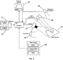
- Figure 2 depicts the elements of one embodiment of the imaging and display system.
- the heart of the system is a processing element, such as a computer 20.
- Other processing elements, such as various types of logic circuit, are within the scope of the invention.
- the computer accepts information on the position and attitude of the helicopter from a navigation system 21.
- this navigation system typically includes a global positioning system (GPS) receiver 110 and an inertial navigation system (INS) 111.
- GPS global positioning system
- INS inertial navigation system
- the helicopter's own navigation system may be used, in which case the computer obtains the information over a data bus.
- an independent navigation system may be used. Additional information may be obtained from the helicopter's navigation database 22, which includes the aircraft flight plan, coordinates of crew-designated landing zones, and terrain elevations. Using the data from the helicopter's navigation database assists the system in overall accuracy and in directing the image sensor to the correct location.
- the processing element 20 also accepts visual information, such as digital imagery, from a sensor.
- this sensor is a digital camera 23, which may be fixed or mounted on a gimbal.
- the sensor images the desired landing zone 24.
- a pulsed illuminator 25 such as a strobe light, is synchronized to the camera.
- a series of images is captured as the approach continues.
- additional sensors may be used to increase the accuracy of the camera position and to characterize slope and other obstacles.
- One or more laser rangefinders 26 are aligned with the camera and furnish slant range to the landing area, while an optional downward-pointing laser rangefinder or radar altimeter gives altitude information over the ground.
- Multiple laser rangefinders or a structured light projector 28 may be used to detect the slope of the landing area.
- sensors 29 may be used to furnish or supplement imagery. These include millimeter wave radar which at certain frequencies can "see through” dust clouds in real time, or forward-looking infrared radar (FLIR) which can image the ground at night without the need for an illuminator.
- FLIR forward-looking infrared radar
- Imagery obtained from the sensor or sensors is sent to the processing element 20 for processing, which involves enhancing the image, placing it in a geo-referenced 3D graphics space, overlaying additional textual and graphical information such as the helicopter's current position relative to the LZ (landing zone), and transforming the imagery to the desired viewpoint.
- the resulting view is shown on a display 30 in sight of the crew. Either a standalone display or an existing aircraft display of sufficient resolution may be used. Suitable controls enable the crew to activate and adjust the system.
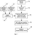
- FIG. 3 depicts the flow of system activation.
- the imaging and display system preferably activates (begins image acquisition) automatically, either before or upon inception of dust cloud formation.
- Activation 34 can be triggered upon reaching certain altitudes and airspeeds 31 derived from the aircraft navigation system or a standalone unit. Because the altitudes and airspeeds at which dust becomes visible are well known, specific triggers can be set. For example, the sensor may be triggered if the helicopter is descending through 100 feet above ground level (AGL) and airspeed is below 40 knots. The proximity of a designated landing zone may also be considered, as obtained from the aircraft's navigation database via the data bus. The system may also be manually triggered 32 when desired. Once the system is triggered, the imaging system begins acquiring images 35 of the landing or takeoff zone.
- AGL ground level
- the system may predict dust cloud formation in advance, based on measurements of ground conditions, e.g. temperature and relative humidity, and models considering the current helicopter location and historical observations of dust cloud formation.
- an additional sensor 33 may detect the formation of a dust cloud to begin and/or stop image acquisition.
- this sensor is either a millimeter or sub-millimeter wave detector having wavelength similar to the characteristic diameter of the dust cloud particulates.
- Inputs may include the following information:
- Errors resulting from inaccuracies in the above inputs may lead to mis-positioning of the transformed imagery and/or helicopter position symbology.
- images are captured from the typical shallow approach angles from which most approaches are made, most errors have the largest effect in the longitudinal direction (along the direction of flight).
- the navigation and gimbal systems are configured to meet a predetermined pitch accuracy.
- the required information is readily available from the helicopter's existing navigation system, such as a GPS and inertial navigation system (INS) over a digital data bus.
- INS inertial navigation system
- the imaging and display system can operate in a listen-only mode, not injecting any data from the system to the helicopter.
- Use of the aircraft's own navigation system saves considerable cost and weight over an independent system.
- IMU inertial measurement unit
- AGL altitude above ground level
- a high-resolution, for example a 4-16 megapixel, digital camera captures a series of images of the landing zone and surrounding terrain prior to brownout.
- an IR-sensitive camera may be used, which may also capture images in daylight.
- image latency i.e. the time between when the image is taken and when it is displayed
- a camera with fast high-resolution image transfer capability to a computer is desired.
- Several industrial cameras have this capability, for example 1/5 second transfer time for a 11-megapixel image.
- the resolution of the image is sufficient to resolve finely detailed hazards such as wires.
- two sensors and stereo imaging may be used to capture a three-dimensional representation of the region.
- Figure 4 depicts a camera mounted in a gimballed camera head 40. Since helicopters typically change attitude during an approach, the gimbal's pan and tilt axes permit the camera to track a geo-referenced location on the ground or remain aligned along the velocity vector (direction of flight).
- the camera head is underslung from the pan axis 41 and the tilt axis 42 is contained within the vertical supports.
- the camera head includes apertures for a camera 43 and co-aligned laser rangefinder 44.
- the camera head may contain a tilt axis only, or be entirely fixed at an optimum angle.
- the latter approach may require a wider angle lens or multiple cameras to ensure coverage of the landing area at various approach angles.
- the camera head is preferably equipped with means for preventing or removing dust accumulation from the lens. These may include stowing the camera head until ready for use, a retractable cover, a spinning aperture, or air jets or wipers to remove dust.
- Lens focal length is selected to provide full coverage of the desired landing area before brownout.
- the Air Force specifies a minimum clear landing area of 150 feet square for the MH-53 helicopter.
- a lens focal length of 75mm provides coverage of the landing area at 50 feet altitude at typical approach angles.
- a zoom lens may be used, generally at the cost of a smaller f/stop (maximum aperture) and therefore reduced light-gathering capability.
- the lens zoom, aperture, and focus may be electronically controlled by the camera, or alternately, through external motorization, for example by means of a system including belts and servo motors.
- Figure 5 depicts the steps in image acquisition. Following system activation 34, images are primarily acquired 35 using a digital camera 51, but may also be obtained through other visual sensors 52, a stored image 53, or an image transmitted from another platform 54.
- the system may evaluate the characteristics of each image, i.e. disappearance of high-frequency details from the image indicates that dust is beginning to obscure the camera. The obscured image is discarded and the last sharp image retrieved from a buffer and used instead.
- a fixed rearward pointing sensor may detect the loss of high-frequency imagery and direct the main camera to stop taking images.
- the crew may also manually stop and restart image acquisition, or capture can be stopped at a given altitude above the ground or distance from the LZ.
- each new image can be projected forward in time, i.e. transformed so that at the time of display the viewpoint reflects the position of the helicopter at that instant, not necessarily the moment the image was actually taken.
- a FLIR (forward-looking infrared) sensor can furnish long range visual information at night to furnish context in which the shorter-range photographic information is placed.
- Images from previous flights into the area may be stored in the computer's memory and transformed as if the image were live. If the helicopter has an aircraft-to-aircraft data link, images may be taken from one aircraft and transferred and displayed on another aircraft in the same formation. This is especially useful in multi-ship landings, where the first aircraft landing causes brownout before subsequent aircraft have a chance to image the area. The position from which the photo was taken must be transmitted as well to allow geo-referencing.
- Offboard image capture also facilitates shifting of imagery in time. For example, a daytime reconnaissance flight can provide imagery for a nighttime operation.
- Geo-referenced images may also be transferred from sources such as unmanned aerial vehicles (UAVs) or other reconnaissance aircraft.
- UAVs unmanned aerial vehicles
- a daytime reconnaissance flight may provide imagery for a nighttime operation, clearer and more covertly than acquiring them at the time of landing.
- the imager is sensitive to both visible and IR wavelengths, allowing for both daytime and nighttime operation.
- a servo may remove IR color correction filtration used during daytime operation from the optical pathway during nighttime operation.
- separate day and night imagers may be used.
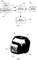
- Figure 6 depicts a cross-section of an illuminator system using a pulsed strobe.
- the strobe head 61 typically krypton-xenon for efficient IR output, is synchronized to the camera control and has sufficient power to fully light the landing area at adequate range.
- a parabolic reflector 62 directs the light to the proper illumination angle.
- An IR-pass filter covers the reflector and prevents almost all visible light from escaping.
- the illuminator may be mounted in the same housing as the camera, or in a separated, gimballed housing slaved to the camera head. Careful positioning avoids backscatter effect into the camera lens.
- the imaging and display system optionally includes a visible light illumination system for use in daytime and non-covert nighttime operations.
- a visible light illumination system for use in daytime and non-covert nighttime operations.
- use of an illumination system can be used to enable short exposure times (approximately 1 ms) and therefore reduced image blur.
- an intensifier is used to amplify light coming into the camera, an illuminator may not be needed for most lighting conditions.
- additional sensors enable 3D analysis of the landing site for slope and general terrain.
- Pilots often have a hard time judging slope at the landing site until the helicopter is quite near the ground or even not until gear contact, especially where the ground is low contrast.
- a transformed 2D image may not show terrain contours sufficiently for the pilot to judge whether slope limits may be exceeded.
- an embodiment of the imaging and display system incorporates one or more active components to measure slope directly.
- active components may include one or more of the following:
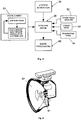
- Figure 7 depicts the process of processing each captured image. As each digital image 71 is captured or otherwise received, it is streamed to the computer for processing. The steps involved in processing may include the following:
- the image is enhanced 72 as necessary to improve contrast and detail. This is particularly useful for night images, where illumination may be inadequate.
- a non-linear transform may be applied to enhance shadow detail, boosting dark areas relative to light areas, and a sharpening algorithm applied to enhance edge detail.
- a virtual camera and projector are placed at the coordinates 73 which are recorded at the time of capture and derived from the navigation system.
- the system may obtain the navigation data from which the image coordinates 73 are derived from one or more navigation systems, such as an aircraft navigation system 76 and an independent navigation system 77.
- the image is then projected 74 as a texture onto a planar surface from that position.
- the virtual camera is set to the desired viewpoint 75 to display the image 78 from any possible point in the graphics space.
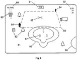
- Figure 8 depicts elements of a representative display for the aircrew.
- the background 81 of the display is taken up with photographic imagery, including obstacles 82. Areas outside of the limits of photographic imagery may be filled with a digital map, derived from the aircraft's terrain database, which helps place the imagery in context as the helicopter approaches.
- the designated landing zone if any, is marked by a dashed box 83.
- Height reference markers 84 at the corners of the box in this case the outline of a 6' man, aid the crew in estimating height of nearby obstacles.
- a cross 85 shows where the aircraft's flight path vector intersects the ground plane in other words, where the helicopter would impact the ground if no changes were made to the helicopter's current flight path.
- the hog, or "helicopter on ground” symbol 86 is placed under the current position of the helicopter. The symbol consists of two roughly circular, concentric shapes conforming to the diameter of the main and tail rotors, with the outer line providing a buffer zone. Rectangles 87 can be used to correspond to the location of the landing gear. If another nearby helicopter is communicating its position, its rotor diameter may be depicted 88 to maintain clearance.
- Textual information is overlaid on the imagery as well.
- an indicator 89 tells the crew of the status of the system. Images taken during the approach may be listed on a stack 90, labeled by distance in nautical miles from the LZ. The currently displayed image is surrounded by a box. The user may select a desired image from this stack for display as an alternative to the most recent image. Other information displayed includes heading 91 and time remaining until landing, altitude, and groundspeed 92.
- Figure 8 depicts a "High 6" view. This viewpoint is placed above and behind the helicopter position along the angle of approach, giving an all-around view of the area surrounding the LZ without introducing significant distortion. By following the helicopter position at a constant distance, both the LZ and the "Helicopter On Ground” (HOG) symbol is always in view. Alternatively, a somewhat higher angle view may be selected to better view the LZ.
- HOG Helicopter On Ground
- the "Line to fixed view” viewpoint starts out from the physical camera (helicopter) location, then travels along a straight line towards the LZ coordinates.
- the viewpoint comes to a stop when the LZ plus a buffer zone fills the screen, and thereafter the fixed view allows the crew to easily study the LZ for hazards.
- the HOG symbol moves in from the bottom of the screen, indicating the helicopter's position relative to the LZ.
- Figure 9 depicts the "Pilot's view” option, wherein the virtual camera is placed either at the location of the physical camera or at the position of the pilot's head.
- the viewpoint follows the roll, pitch, and heading changes of the aircraft, giving a close up view of the LZ, although the area around the aircraft for main and tail rotor clearance is "behind the viewpoint and therefore not displayed.
- Figure 10 depicts the "Top view” option, where the LZ is viewed from high above, directly downward, particularly useful for debugging and calibration
- Flat objects in the ground plane, such as runway markings, are accurately rendered.
- objects with a vertical component such as trees
- objects with a vertical component may be distorted because a 2D rendering of a 3D object is increasingly distorted the more the viewpoint angle (90°) diverges from the capture angle (about 10°).
- the image obtained is of high resolution, it may be analyzed in real time to aid obstacle detection and identification.
- the image may be analyzed for hanging cables by looking for catenary shapes between vertical elements. Any detected cables are highlighted on the display.
- a colored border may be used to indicate the "age” of the image to warn the pilots that obstacles may have appeared in the interim.
- the border may turn from green to red indicate an older and therefore less reliable image.
- Iconic representations of hazards arising subsequent to image capture may also be overlaid on the high resolution image.
- a red circle may be positioned at the location of a person that has entered the landing area.
- sensors such as millimeter wave radar (active or passive), and infrared imaging.
- the invention makes use of the sensors in a detection role to provide the pilot with an easily interpreted, dynamic display.
- tracking of pre-designated hazards and targets indicated by RFID (Radio Frequency Identification) tags, transponders, and beacons may also be integrated.
- RFID Radio Frequency Identification
- buttons or touchscreen buttons may be provided to allow the crew to operate the system.
- Functions may include system on/off, automatic/manual activation, viewpoint, manual pointing, and others as needed.
- the imaging and display system can be used to take overhead reconnaissance photos of any en-route area for later use. For example, it may be desirable to image an area to aid a mission briefing for a later landing, or to collect landing imagery for a helicopter not equipped with the system.
- the imaging and display system may be used during takeoff in obscured conditions as well.
- Several crashes have occurred when pilots became disoriented upon taking off into a dust cloud.
- the image is taken before the collective is raised and lift generated.
- the (preferably gimbaled) camera field of view is shifted to above the horizon to obtain the image.
- the imaging and display system has been described for use with helicopters, in actual fact, it may be used with any other vertical-takeoff-and-landing aircraft (VTOL), such as tilt-rotor aircraft or jump jets.
- VTOL vertical-takeoff-and-landing aircraft
- an embodiment of the imaging and display system is typically deployed in low-visibility conditions such as brownouts or whiteouts, in actual fact, the imaging and display system finds application in any condition wherein an enhanced situational awareness of a VTOL's landing and takeoff zones is needed or desired.
- the specification and drawings are, accordingly, to be regarded in an illustrative sense rather than a restrictive sense.
Landscapes
- Engineering & Computer Science (AREA)
- Radar, Positioning & Navigation (AREA)
- Remote Sensing (AREA)
- Aviation & Aerospace Engineering (AREA)
- Physics & Mathematics (AREA)
- General Physics & Mathematics (AREA)
- Automation & Control Theory (AREA)
- Traffic Control Systems (AREA)
- Studio Devices (AREA)
- Position Fixing By Use Of Radio Waves (AREA)
- Instructional Devices (AREA)
Claims (19)
- Ein System, um Situationsbewusstsein in einem Vertikal-Start- und Lande(VTOL)-Luftfahrzeug (12) zu verbessern, das folgende Merkmale aufweist:ein Element (35), das dazu ausgebildet ist, ein klares zweidimensionales visuelles Bild (71) einer Start- oder Landezone (LZ) vor der Bildung eines Brownout- oderWhiteout-Zustandes zu empfangen;ein Element (73), das dazu ausgebildet ist, Navigationsinformationen des Luftfahrzeugs (12) zu empfangen, einschließlich der aktuellen Position des Luftfahrzeugs;ein Verarbeitungselement (20), dass programmiert ist, zumPlatzieren (74) des klaren zweidimensionalen visuellen Bildes (71) in einen geobezogenen 3D-Grafikraum,Überlagern einer Darstellung der aktuellen Position des Luftfahrzeuges relativ zu der Start- oder Landezone (LZ), undUmwandeln des Bildmaterials basierend auf den Navigationsinformationen (73) des Luftfahrzeuges (12); undein Element (78), das dazu ausgebildet ist, die Bilddarstellung an eine Anzeigevorrichtung (30) auszugeben, wobei die Bilddarstellung, die auf der Anzeigevorrichtung (30) angezeigt wird, die Position des Luftfahrzeuges (12) relativ zu der Start- oder Landezone (LZ) zeigt.
- Das System gemäß Anspruch 1, bei dem das klare zweidimensionale visuelle Bild (71) der Start- oder Landezone (LZ) eines oder mehrere der folgenden Merkmale aufweist:eine Ausgabe von einer Digitalkamera (23);eine Ausgabe von einem Voraussichtinfrarotradar;ein gespeichertes digitales Bild der Start- oder Landezone (LZ); undBildmaterial der Start- oder Landezone (LZ), das von einer Quelle außerhalb des Luftfahrzeuges gesendet wird.
- Das System gemäß Anspruch 1, bei dem die Navigationsinformationen des Luftfahrzeuges (12) die aktuelle Lage des Luftfahrzeuges umfassen.
- Das System gemäß Anspruch 2, das ferner zumindest einen zusätzlichen Sensor (29) für zumindest eines des Folgenden aufweist:Verbessern einer Genauigkeit der Position des Luftfahrzeuges relativ zu der Start- oder Landezone (LZ);Charakterisieren einer Neigung und/oder anderer Hindernisse; undDetektieren einer Bildung einer Staubwolke, um die Bilderfassung zu beginnen oder anzuhalten.
- Das System gemäß Anspruch 4, bei dem zumindest ein zusätzlicher Sender (29) zumindest eines der folgenden Merkmale aufweist:einen oder mehrere Laserentfernungsmesser, um der Start- oder Landezone (LZ) eine Schrägenentfernung zu liefern;einen nach unten gerichteten Laserentfernungsmesser, um Höheninformationen zu geben; undeinen Radarhöhenmesser, um Höheninformationen zu geben.
- Das System gemäß Anspruch 1, das ferner folgendes Merkmal aufweist:ein Auslöseelement (34), um eine Bilderfassung durch das System zu aktivieren, wobei das Auslöseelement (34) dahingehend einstellbar ist, eine Bilderfassung (35) bei einem oder mehreren von einer spezifischen Fluggeschwindigkeit, einer spezifischen Höhe über Grund oder einer Nähe zu einer bestimmten Landezone (LZ) auszulösen.
- Das System gemäß Anspruch 1, das ferner folgendes Merkmal aufweist:ein Auslöseelement (34), um eine Bilderfassung durch das System zu aktivieren, wobei die Bilderfassung (35) manuell ausgelöst wird (32).
- Das System gemäß Anspruch 1, das ferner folgendes Merkmal aufweist:ein Auslöseelement (34), um eine Bilderfassung durch das System zu aktivieren, wobei die Bilderfassung (35) durch Detektion einer Bildung eines Brownout- oder Whiteout-Zustandes entweder ausgelöst oder ausgesetzt wird.
- Das System gemäß Anspruch 1, das ferner folgendes Merkmal aufweist:eine Komponente zum direkten Messen einer Neigung an der Start- oder Landezone (LZ), wobei die Komponente zum direkten Messen einer Neigung eines der folgenden Merkmale aufweist:eine Einrichtung zum Projizieren eines Musters von stark fokussiertem Licht auf die Start- oder Landezone (LZ), wobei eine Distorsion eines reflektierten Musters durch das Verarbeitungselement analysiert wird, um 3D-Informationen zu Gelände und großen Hindernissen bereitzustellen;ein Multistrahllaser, wobei eine Neigung der Start- oder Landezone (LZ) durch Messen einer Rücklaufzeit der mehreren Laser berechnet werden kann;eine 3D-Bilderzeugungsvorrichtung, die zwei durch eine ausreichende Basislinie getrennte Kameras aufweist, um die Start- oder Landezone (LZ) in 3D zu charakterisieren; undeine Einrichtung zum Durchführen einer Pixel-für-Pixel-Optischer-Fluss-Analyse, um Informationen zu Konturen bereitzustellen.
- Das System gemäß Anspruch 1, das ferner folgende Merkmale aufweist:ein Navigationssystem, das die Navigationsinformationen an das Element zum Empfangen von Navigationsinformationen sendet, wobei das Navigationssystem eines oder beide der folgenden Merkmale aufweist:das Navigationssystem des Luftfahrzeuges, wobei die Navigationsinformationen über ein Datensignal an das Verarbeitungselement (20) gesendet werden; undein Navigationssystem, das in dem System zur Bilderzeugung und Anzeige enthalten ist, wobei das enthaltene Navigationssystem eines oder beide eines GPS(globales Bestimmungssystem)-Sensors oder eines Trägheitsmessgerätes umfasst.
- Das System gemäß Anspruch 10, das ferner folgendes Merkmal aufweist:eine Navigationsdatenbank, wobei die Navigationsdatenbank Navigationsdaten zumindest hinsichtlich des Flugplanes des Luftfahrzeuges, der Koordinaten durch die Besatzung bestimmter Landezonen (LZ) und der Geländehöhen speichert.
- Das System gemäß Anspruch 1, bei dem die Navigationsinformationen Informationen hinsichtlich Position und Lage des Luftfahrzeuges (12) aufweisen, wobei die Navigationsinformationen eines oder mehrere der folgenden Merkmale umfassen:Breite und Länge;Höhe über Grund;Luftfahrzeuglage, einschließlich Nicken, Rollen und/oder Steuerkurs;Entfernung zu einer Landezone; undKamerakopfschwenk- und Kamerakopfneigewinkel, wobei Schwenk- und Neigeachsen es einem Sensor ermöglichen, einen geobezogenen Grundstandort zu verfolgen oder zu der Flugrichtung ausgerichtet zu bleiben.
- Das System gemäß Anspruch 1, das ferner folgendes Merkmal aufweist:einen Verstärker, um Licht zu verstärken, das in ein Bildaufnahmegerät einfällt.
- Das System gemäß Anspruch 1, das ferner folgendes Merkmal aufweist:eine Beleuchtungseinrichtung (25) zum Bereitstellen von zusätzlichem Licht zum Aufnehmen von Bilddaten in Schwachlichtsituationen.
- Das System gemäß Anspruch 14, bei dem die Beleuchtungseinrichtung (25) ferner folgende Merkmale aufweist:eine gepulste Beleuchtungseinrichtung, die mit einem visuellen Sensor synchronisiert ist, wobei die gepulste Beleuchtungseinrichtung über eine ausreichende Leistung verfügt, um die Start- oder Landezone (LZ) vollständig zu beleuchten, und wobei die Beleuchtungseinrichtung ferner folgende Merkmale aufweist:eine parabolischen Reflektor (62), um das Licht zu dem gewünschten Beleuchtungswinkel zu richten, undein IR-Passfilter, das den parabolischen Reflektor (62) abdeckt, um zu verhindern, dass sichtbares Licht austritt.
- Das System gemäß Anspruch 2, das ferner folgendes Merkmal aufweist:ein lenkbares Kardanelement, wobei die Digitalkamera in dem lenkbaren Kardanelement untergebracht ist.
- Das System gemäß Anspruch 1, bei dem das Verarbeitungselement, das dazu programmiert ist, ein oder mehrere verbesserte Bilder zu erzeugen, die die Start- oder Landezone (LZ) darstellen, Einrichtungen für Folgendes aufweist:visuelles Verbessern des klaren zweidimensionalen visuellen Bildes (71), um Kontrast und Detail zu optimieren; undUmwandeln des klaren zweidimensionalen visuellen Bildes (71) zu einem gewünschten Blickwinkel.
- Das System gemäß Anspruch 1, bei dem die Anzeige (30) entweder eine eigenständige Anzeige oder eine bestehende Luftfahrzeuganzeige mit ausreichender Auflösung aufweist.
- Ein Verfahren zum Verbessern von Situationsbewusstsein bei einem Vertikal-Start- und Lande(VTOL)-Luftfahrzeug (12), das folgende Schritte aufweist:Erfassen eines klaren zweidimensionalen visuellen Bildes (71) einer Start- oder Landezone (LZ) vor der Bildung eines Brownout- oder Whiteout-Zustandes;Erfassen von Navigationsinformationen des Luftfahrzeugs (12), einschließlich der aktuellen Position des Luftfahrzeugs;Platzieren (74) des klaren zweidimensionalen visuellen Bildes (71) in einen geobezogenen 3D-Grafikraum;Überlagern einer Darstellung der aktuellen Position des Luftfahrzeuges relativ zu der Start- oder Landezone (LZ);Umwandeln (75) des Bildmaterials basierend auf den Navigationsinformationen (73) des Luftfahrzeuges (12); undAnzeigen des Bildmaterials, die die Position des Luftfahrzeuges (12) relativ zu der Start- oder Landezone (LZ) zeigt, für eine Besatzung des Luftfahrzeuges (12).
Applications Claiming Priority (2)
| Application Number | Priority Date | Filing Date | Title |
|---|---|---|---|
| US82765106P | 2006-09-29 | 2006-09-29 | |
| US11/856,557 US8019490B2 (en) | 2006-09-29 | 2007-09-17 | Imaging and display system to aid helicopter landings in brownout conditions |
Publications (3)
| Publication Number | Publication Date |
|---|---|
| EP1906151A2 EP1906151A2 (de) | 2008-04-02 |
| EP1906151A3 EP1906151A3 (de) | 2011-09-07 |
| EP1906151B1 true EP1906151B1 (de) | 2016-12-14 |
Family
ID=38866711
Family Applications (1)
| Application Number | Title | Priority Date | Filing Date |
|---|---|---|---|
| EP07018865.1A Not-in-force EP1906151B1 (de) | 2006-09-29 | 2007-09-25 | Abbildungs- und Anzeigesystem zur Unterstützung von Hubschrauberlandungen unter Brownout-Bedingungen |
Country Status (2)
| Country | Link |
|---|---|
| US (1) | US8019490B2 (de) |
| EP (1) | EP1906151B1 (de) |
Families Citing this family (102)
| Publication number | Priority date | Publication date | Assignee | Title |
|---|---|---|---|---|
| US8749343B2 (en) * | 2007-03-14 | 2014-06-10 | Seth Cirker | Selectively enabled threat based information system |
| US20100019927A1 (en) * | 2007-03-14 | 2010-01-28 | Seth Cirker | Privacy ensuring mobile awareness system |
| US8379087B1 (en) * | 2007-05-01 | 2013-02-19 | The United States Of America As Represented By The Secretary Of The Navy | Attitude estimation using ground imagery |
| EP2188179A4 (de) * | 2007-08-17 | 2016-08-03 | Sikorsky Aircraft Corp | Stabilisierte annäherung an einen punkt in einer abgeschwächten visuellen umgebung |
| US7874744B2 (en) * | 2007-09-21 | 2011-01-25 | Seth Cirker | Privacy ensuring camera enclosure |
| US8123419B2 (en) * | 2007-09-21 | 2012-02-28 | Seth Cirker | Privacy ensuring covert camera |
| US7777668B2 (en) * | 2008-04-08 | 2010-08-17 | Honeywell International Inc. | Radar altimeter with forward looking radar and data transfer capabilities |
| US8165728B2 (en) * | 2008-08-19 | 2012-04-24 | The United States Of America As Represented By The Secretary Of The Navy | Method and system for providing a GPS-based position |
| FR2935793B1 (fr) * | 2008-09-05 | 2010-12-10 | Thales Sa | Dispositif de visualisation pour aeronef comprenant des moyens d'affichage de la destination finale et procede d'affichage associe |
| PL2166372T3 (pl) | 2008-09-23 | 2012-01-31 | Eads Deutschland Gmbh | Interfejs do komunikacji człowieka z maszyną do wspierania pilota podczas startu lub lądowania urządzenia latającego przy ograniczonej widoczności |
| US20100114408A1 (en) * | 2008-10-31 | 2010-05-06 | Honeywell International Inc. | Micro aerial vehicle quality of service manager |
| US8188890B2 (en) * | 2008-11-13 | 2012-05-29 | Honeywell International Inc. | Systems and methods for enhancing obstacles and terrain profile awareness |
| US8065082B2 (en) * | 2008-11-14 | 2011-11-22 | Honeywell International Inc. | Display systems with enhanced symbology |
| US8482417B2 (en) * | 2008-11-17 | 2013-07-09 | David Stewart | System and method for network-based jump area monitoring |
| AU2009327362A1 (en) | 2008-12-19 | 2011-08-04 | Xollai, Llc | System and method for determining an orientation and position of an object |
| US8264379B2 (en) * | 2009-03-10 | 2012-09-11 | Honeywell International Inc. | Methods and systems for correlating data sources for vehicle displays |
| US8354951B2 (en) * | 2009-05-07 | 2013-01-15 | Intelligent Sciences, Ltd. | Short baseline helicopter positioning radar for low visibility |
| EP2440982A4 (de) * | 2009-06-12 | 2016-08-10 | Saab Ab | Zentrierung über einem vordefinierten bereich einer landefläche |
| DE102009035191B4 (de) | 2009-07-29 | 2013-07-25 | Eads Deutschland Gmbh | Verfahren zur Erzeugung einer sensorgestützten, synthetischen Sicht zur Landeunterstützung von Helikoptern unter Brown-Out oder White-Out-Bedingungen |
| IL201336A (en) * | 2009-10-01 | 2014-03-31 | Rafael Advanced Defense Sys | System and method for assisting navigation of a vehicle in circumstances where there is a possibility of the view being obscured |
| US8704891B2 (en) * | 2009-12-23 | 2014-04-22 | The United States Of America As Represented By The Secretary Of The Navy | External mounted electro-optic sight for a vehicle |
| US9105115B2 (en) * | 2010-03-16 | 2015-08-11 | Honeywell International Inc. | Display systems and methods for displaying enhanced vision and synthetic images |
| US20110254706A1 (en) * | 2010-04-20 | 2011-10-20 | Sikorsky Aircraft Corporation | Methods and Systems Involving Viewing Angles in Aircraft Displays |
| US9036861B2 (en) * | 2010-04-22 | 2015-05-19 | The University Of North Carolina At Charlotte | Method and system for remotely inspecting bridges and other structures |
| US9014415B2 (en) * | 2010-04-22 | 2015-04-21 | The University Of North Carolina At Charlotte | Spatially integrated aerial photography for bridge, structure, and environmental monitoring |
| US8266181B2 (en) | 2010-05-27 | 2012-09-11 | International Business Machines Corporation | Key-break and record-loop processing in parallel data transformation |
| US9055226B2 (en) * | 2010-08-31 | 2015-06-09 | Cast Group Of Companies Inc. | System and method for controlling fixtures based on tracking data |
| US9350923B2 (en) | 2010-08-31 | 2016-05-24 | Cast Group Of Companies Inc. | System and method for tracking |
| JP5690539B2 (ja) | 2010-09-28 | 2015-03-25 | 株式会社トプコン | 自動離着陸システム |
| JP5618840B2 (ja) * | 2011-01-04 | 2014-11-05 | 株式会社トプコン | 飛行体の飛行制御システム |
| CA2824932C (en) | 2011-01-14 | 2016-03-22 | Bell Helicopter Textron Inc. | Flight control laws for vertical flight path control |
| US8995713B2 (en) * | 2011-04-25 | 2015-03-31 | Fujitsu Limited | Motion tracking using identifying feature requiring line of sight of camera |
| JP5775354B2 (ja) | 2011-04-28 | 2015-09-09 | 株式会社トプコン | 離着陸ターゲット装置及び自動離着陸システム |
| TWI449420B (zh) * | 2011-05-31 | 2014-08-11 | Nat Applied Res Laboratoires | 搜索取像系統及其控制方法 |
| US8711220B2 (en) * | 2011-08-23 | 2014-04-29 | Aireyes, Inc. | Automatic detection of image degradation in enhanced vision systems |
| US9563723B1 (en) | 2011-10-30 | 2017-02-07 | Lockheed Martin Corporation | Generation of an observer view in a virtual environment |
| ES2530366T3 (es) * | 2012-01-20 | 2015-03-02 | Airbus Defence & Space Gmbh | Procedimiento y sistema de asistencia al aterrizaje para helicópteros |
| EP2662722B1 (de) | 2012-05-11 | 2016-11-23 | AGUSTAWESTLAND S.p.A. | Hubschrauber und Verfahren zur Anzeige einer visuellen Information im Zusammenhang mit den Flugparametern für den Bediener eines Hubschraubers |
| US8810435B2 (en) | 2012-06-28 | 2014-08-19 | Honeywell International Inc. | Apparatus and method for displaying a helicopter approach to an airport landing pad |
| US8918234B2 (en) * | 2012-09-17 | 2014-12-23 | Bell Helicopter Textron Inc. | Landing point indication system |
| US20140207315A1 (en) * | 2013-01-23 | 2014-07-24 | Honeywell International Inc. | Apparatus and method for displaying a helicopter terrain intercept point during landing |
| CN103991553B (zh) * | 2013-02-19 | 2016-02-24 | 成都海存艾匹科技有限公司 | 飞机精准着陆辅助装置 |
| RU2523855C2 (ru) * | 2013-02-20 | 2014-07-27 | Николай Александрович Саврасов | Система обнаружения помех для посадки и взлета вертолета |
| US9669940B1 (en) * | 2013-06-27 | 2017-06-06 | Rockwell Collins, Inc. | Latency-reducing image generating system, device, and method |
| US10696387B2 (en) | 2013-09-27 | 2020-06-30 | Dann M Allen | Helicopter rotor with a mechanical means for configuring rotor tips to control brown outs |
| US9970766B2 (en) | 2013-09-30 | 2018-05-15 | Northrop Grumman Systems Corporation | Platform-mounted artificial vision system |
| US9769387B1 (en) * | 2013-11-05 | 2017-09-19 | Trace Live Network Inc. | Action camera system for unmanned aerial vehicle |
| KR101842031B1 (ko) * | 2013-12-11 | 2018-03-26 | 한화테크윈 주식회사 | 감시 시스템 |
| US9598011B2 (en) | 2014-01-09 | 2017-03-21 | Northrop Grumman Systems Corporation | Artificial vision system |
| FR3016694B1 (fr) | 2014-01-20 | 2016-01-22 | Airbus Helicopters | Procede d'assistance a la navigation pour giravion, par affichage dynamique d'une representation du monde exterieur construite en vol instantanement et/ou en differe |
| JP6325834B2 (ja) * | 2014-02-07 | 2018-05-16 | 三菱航空機株式会社 | 整備支援システムおよび整備支援方法 |
| US9340282B2 (en) * | 2014-03-17 | 2016-05-17 | Honeywell International Inc. | System and method for displaying vertical reference on a rotorcraft system |
| CN106415422B (zh) * | 2014-05-12 | 2020-08-28 | 湾流航空航天公司 | 利用多传感器增益调度的先进飞机视觉系统 |
| US9826164B2 (en) * | 2014-05-30 | 2017-11-21 | Furuno Electric Co., Ltd. | Marine environment display device |
| WO2016007796A1 (en) | 2014-07-10 | 2016-01-14 | Breeze-Eastern Corporation | Helicopter hoist systems, devices, and methodologies |
| FR3025114A1 (fr) * | 2014-08-26 | 2016-03-04 | Parrot | Procede de controle dynamique en depart lance d'un drone a voilure tournante |
| EP3201077B1 (de) | 2014-10-01 | 2020-05-20 | Sikorsky Aircraft Corporation | Doppelrotor, drehflügelflugzeug |
| US20170267338A1 (en) * | 2014-10-01 | 2017-09-21 | Sikorsky Aircraft Corporation | Acoustic signature variation of aircraft utilizing a clutch |
| US9523580B2 (en) * | 2014-12-02 | 2016-12-20 | Honeywell International Inc. | System and method for aiding a pilot in locating an out of view landing site |
| US9435635B1 (en) | 2015-02-27 | 2016-09-06 | Ge Aviation Systems Llc | System and methods of detecting an intruding object in a relative navigation system |
| US10029804B1 (en) * | 2015-05-14 | 2018-07-24 | Near Earth Autonomy, Inc. | On-board, computerized landing zone evaluation system for aircraft |
| US9752893B2 (en) | 2015-07-30 | 2017-09-05 | Honeywell International Inc. | Onboard aircraft systems and methods to identify moving landing platforms |
| US9659412B2 (en) * | 2015-07-30 | 2017-05-23 | Honeywell International Inc. | Methods and systems for displaying information on a heads-up display |
| US10540901B2 (en) | 2015-11-23 | 2020-01-21 | Kespry Inc. | Autonomous mission action alteration |
| US10060741B2 (en) * | 2015-11-23 | 2018-08-28 | Kespry Inc. | Topology-based data gathering |
| US20180373243A1 (en) * | 2016-01-01 | 2018-12-27 | USDrobotics Inc. | System and Method for Safe Utilization of Unmanned Automated Vehicles in Entertainment Venues |
| WO2017132074A1 (en) * | 2016-01-26 | 2017-08-03 | Russell David Wayne | System and method for targeted imaging from collection platforms |
| US9745078B2 (en) | 2016-02-01 | 2017-08-29 | Honeywell International Inc. | Systems and methods of precision landing for offshore helicopter operations using spatial analysis |
| JP2017204094A (ja) * | 2016-05-10 | 2017-11-16 | 富士通株式会社 | 視線特定プログラム、視線特定装置、及び視線特定方法 |
| US9802656B1 (en) * | 2016-06-07 | 2017-10-31 | Toyota Motor Engineering & Manufacturing North America, Inc. | Vehicle sensing systems including retractable mounting structures |
| CN114476105B (zh) * | 2016-08-06 | 2025-01-03 | 深圳市大疆创新科技有限公司 | 自动着陆表面地形评估以及相关的系统和方法 |
| US10121117B1 (en) | 2016-09-08 | 2018-11-06 | Amazon Technologies, Inc. | Drone location signature filters |
| US10049589B1 (en) * | 2016-09-08 | 2018-08-14 | Amazon Technologies, Inc. | Obstacle awareness based guidance to clear landing space |
| US10198955B1 (en) | 2016-09-08 | 2019-02-05 | Amazon Technologies, Inc. | Drone marker and landing zone verification |
| US10254767B1 (en) * | 2017-01-25 | 2019-04-09 | Amazon Technologies, Inc. | Determining position or orientation relative to a marker |
| US10099802B2 (en) * | 2017-02-14 | 2018-10-16 | Honeywell International Inc. | Methods and systems to detect and alert a dynamic rollover condition for an aircraft |
| GB2557715B (en) * | 2017-02-28 | 2019-04-17 | Matthew Russell Iain | Unmanned aerial vehicles |
| US20210394923A1 (en) * | 2017-07-10 | 2021-12-23 | Autel Robotics Co., Ltd. | Aircraft control method and apparatus and aircraft |
| TWI659390B (zh) * | 2017-08-23 | 2019-05-11 | 國立彰化師範大學 | 應用於物件檢測之攝影機與雷射測距儀的數據融合方法 |
| US10872534B2 (en) | 2017-11-01 | 2020-12-22 | Kespry, Inc. | Aerial vehicle inspection path planning |
| FR3075985B1 (fr) * | 2017-12-21 | 2019-11-15 | Thales | Procede et systeme d'harmonisation duale d'un systeme d'affichage tete haute porte pour rendre conforme l'affichage d'informations de pilotage d'un aeronef avec le monde reel exterieur |
| CN108363034B (zh) * | 2018-03-20 | 2023-09-22 | 陈昌志 | 热磁信标透雾导航着陆系统 |
| CA3097102C (en) * | 2018-05-09 | 2023-01-03 | Kawasaki Jukogyo Kabushiki Kaisha | Sampling method and sampling system |
| US11030908B2 (en) | 2018-05-17 | 2021-06-08 | Rockwell Collins, Inc. | System and method for identification and assessment of abnormal behavior of nearby aircraft |
| US12498718B2 (en) | 2018-08-07 | 2025-12-16 | Reliable Robotics Corporation | Landing site localization for dynamic control of an aircraft toward a landing site |
| US11749126B2 (en) | 2018-08-07 | 2023-09-05 | Reliable Robotics Corporation | Landing site localization for dynamic control of an aircraft toward a landing site |
| US10935987B2 (en) * | 2018-08-07 | 2021-03-02 | Reliable Robotics Corporation | Landing site localization for dynamic control of an aircraft toward a landing site |
| CN109341686B (zh) * | 2018-12-04 | 2023-10-27 | 中国航空工业集团公司西安航空计算技术研究所 | 一种基于视觉-惯性紧耦合的飞行器着陆位姿估计方法 |
| CN110108269B (zh) * | 2019-05-20 | 2023-01-17 | 电子科技大学 | 基于多传感器数据融合的agv定位方法 |
| WO2020251647A1 (en) * | 2019-06-10 | 2020-12-17 | Leon Ruben | Independently operable low-visibility aid device |
| JP6832473B1 (ja) * | 2019-10-08 | 2021-02-24 | 楽天株式会社 | 処理システム、無人で飛行可能な航空機、及び粉塵状態推定方法 |
| EP3835726A1 (de) * | 2019-12-13 | 2021-06-16 | HENSOLDT Sensors GmbH | Landehilfesystem und landehilfeverfahren |
| US11670181B2 (en) * | 2020-01-22 | 2023-06-06 | Honeywell International Inc. | Systems and methods for aiding landing of vertical takeoff and landing vehicle |
| CN111665508B (zh) * | 2020-04-28 | 2022-10-25 | 北京安达维尔航空设备有限公司 | 直升机载地形跟随与回避可视化导航系统以及导航方法 |
| FR3110728B1 (fr) | 2020-05-19 | 2022-04-29 | Thales Sa | Dispositif électronique d'affichage de symboles exocentrés, procédé d'affichage et produit programme d'ordinateur associés |
| US12033528B2 (en) | 2021-02-04 | 2024-07-09 | Honeywell International Inc. | Display systems and methods |
| US12306308B2 (en) * | 2021-02-17 | 2025-05-20 | Honeywell International Inc. | Structured light navigation aid |
| US11847925B2 (en) | 2021-04-19 | 2023-12-19 | Honeywell International Inc. | Systems and methods to display an elevated landing port for an urban air mobility vehicle |
| US12269610B2 (en) | 2021-11-15 | 2025-04-08 | Honeywell International Inc. | Systems and methods for providing safe landing assistance for an aerial vehicle |
| EP4181104B1 (de) * | 2021-11-15 | 2024-09-11 | Honeywell International Inc. | Systeme und verfahren zur bereitstellung einer sicheren landehilfe für ein fahrzeug |
| FR3135810B1 (fr) * | 2022-05-19 | 2024-10-11 | Thales Sa | Procédé de génération d’une image périphérique d’un aéronef, dispositif électronique de génération et produit programme d’ordinateur associés |
| US12462692B2 (en) * | 2024-01-17 | 2025-11-04 | Honeywell International Inc. | System and method for camera assisted stable approach using sensor fusion |
Citations (1)
| Publication number | Priority date | Publication date | Assignee | Title |
|---|---|---|---|---|
| EP1555545A1 (de) * | 2004-01-19 | 2005-07-20 | Rafael Armament Development Authority Ltd. | Mehrstrahlenbündellaserentfernungsmesser |
Family Cites Families (8)
| Publication number | Priority date | Publication date | Assignee | Title |
|---|---|---|---|---|
| DE3942770A1 (de) * | 1989-12-23 | 1991-07-11 | Dornier Luftfahrt | Entfernungsbildkamera |
| US7390092B2 (en) * | 2002-11-08 | 2008-06-24 | Belliveau Richard S | Image projection lighting devices with visible and infrared imaging |
| EP1616228A4 (de) * | 2003-03-31 | 2013-05-29 | Sikorsky Aircraft Corp | Technische entwurfskonzepte zur verbesserung der helikopterhindernisvermeidung und des betriebs in brownout -bedingungen |
| US20050168573A1 (en) * | 2003-06-30 | 2005-08-04 | Dennis Michael R. | Plural-mode surveillance system and methodology with differentiated, selectable, twin-output display |
| US7253398B2 (en) * | 2004-07-22 | 2007-08-07 | Flir Systems Inc. | Sensor system with improved operator input devices |
| DE102004051625B4 (de) * | 2004-10-23 | 2006-08-17 | Eads Deutschland Gmbh | Verfahren zur Pilotenunterstützung bei Landungen von Helicoptern im Sichtflug unter Brown-Out oder White-Out Bedingungen |
| US7463954B1 (en) * | 2004-11-29 | 2008-12-09 | Honeywell International Inc. | Terrain augmented display symbology |
| WO2007146034A2 (en) * | 2006-06-07 | 2007-12-21 | Pursuit Engineering Llc | Highly-efficient optical collection and reflection surface(s) and molding system for manufacture of same |
-
2007
- 2007-09-17 US US11/856,557 patent/US8019490B2/en active Active
- 2007-09-25 EP EP07018865.1A patent/EP1906151B1/de not_active Not-in-force
Patent Citations (1)
| Publication number | Priority date | Publication date | Assignee | Title |
|---|---|---|---|---|
| EP1555545A1 (de) * | 2004-01-19 | 2005-07-20 | Rafael Armament Development Authority Ltd. | Mehrstrahlenbündellaserentfernungsmesser |
Also Published As
| Publication number | Publication date |
|---|---|
| US8019490B2 (en) | 2011-09-13 |
| EP1906151A3 (de) | 2011-09-07 |
| US20090138138A1 (en) | 2009-05-28 |
| EP1906151A2 (de) | 2008-04-02 |
Similar Documents
| Publication | Publication Date | Title |
|---|---|---|
| EP1906151B1 (de) | Abbildungs- und Anzeigesystem zur Unterstützung von Hubschrauberlandungen unter Brownout-Bedingungen | |
| US11933613B2 (en) | Ground control point assignment and determination system | |
| US12428147B2 (en) | Unmanned aerial vehicle inspection system | |
| US12007761B2 (en) | Unmanned aerial vehicle inspection system | |
| EP3740785B1 (de) | Automatische kameragetriebene flugzeugsteuerung zur radaraktivierung | |
| US8554395B2 (en) | Method and system for facilitating autonomous landing of aerial vehicles on a surface | |
| US7839322B2 (en) | System for detecting obstacles in the vicinity of a touchdown point | |
| CN107871405B (zh) | 利用视觉信息进行空中碰撞威胁的检测与评估 | |
| EP3111170B1 (de) | Projizierte synthetische sicht | |
| CN111399535A (zh) | 一种无人机避障方法、装置、无人机及存储介质 | |
| JP7011908B2 (ja) | 光学情報処理装置、光学情報処理方法および光学情報処理用プログラム | |
| WO2023102911A1 (zh) | 数据采集方法、数据展示方法、数据处理方法、飞行器的降落方法、数据展示系统及存储介质 | |
| US12530980B2 (en) | Method for identifying a landing zone, computer program and electronic device therefor | |
| Scholz et al. | Concept for Sensor and Processing Equipment for Optical Navigation of VTOL during Approach and Landing | |
| EP3702871B1 (de) | Entwurf und verarbeitung multispektraler sensoren für autonomen flug | |
| JP2022028894A (ja) | 光学情報処理装置、光学情報処理方法および光学情報処理用プログラム | |
| Hecker et al. | Integrity Enhancement of an Integrated Navigation System with Optical Sensors | |
| EP3835726A1 (de) | Landehilfesystem und landehilfeverfahren |
Legal Events
| Date | Code | Title | Description |
|---|---|---|---|
| PUAI | Public reference made under article 153(3) epc to a published international application that has entered the european phase |
Free format text: ORIGINAL CODE: 0009012 |
|
| 17P | Request for examination filed |
Effective date: 20070925 |
|
| AK | Designated contracting states |
Kind code of ref document: A2 Designated state(s): AT BE BG CH CY CZ DE DK EE ES FI FR GB GR HU IE IS IT LI LT LU LV MC MT NL PL PT RO SE SI SK TR |
|
| AX | Request for extension of the european patent |
Extension state: AL BA HR MK YU |
|
| PUAL | Search report despatched |
Free format text: ORIGINAL CODE: 0009013 |
|
| AK | Designated contracting states |
Kind code of ref document: A3 Designated state(s): AT BE BG CH CY CZ DE DK EE ES FI FR GB GR HU IE IS IT LI LT LU LV MC MT NL PL PT RO SE SI SK TR |
|
| AX | Request for extension of the european patent |
Extension state: AL BA HR MK RS |
|
| RIC1 | Information provided on ipc code assigned before grant |
Ipc: G01C 23/00 20060101AFI20110729BHEP |
|
| AKY | No designation fees paid | ||
| RBV | Designated contracting states (corrected) |
Designated state(s): AT BE BG CH CY LI |
|
| RBV | Designated contracting states (corrected) |
Designated state(s): AT BE BG CH CY CZ DE DK EE ES FI FR GB GR HU IE IS IT LI LT LU LV MC MT NL PL PT RO SE SI SK TR |
|
| REG | Reference to a national code |
Ref country code: DE Ref legal event code: R108 Effective date: 20120516 |
|
| 17Q | First examination report despatched |
Effective date: 20140203 |
|
| GRAP | Despatch of communication of intention to grant a patent |
Free format text: ORIGINAL CODE: EPIDOSNIGR1 |
|
| INTG | Intention to grant announced |
Effective date: 20160627 |
|
| GRAS | Grant fee paid |
Free format text: ORIGINAL CODE: EPIDOSNIGR3 |
|
| GRAA | (expected) grant |
Free format text: ORIGINAL CODE: 0009210 |
|
| AK | Designated contracting states |
Kind code of ref document: B1 Designated state(s): AT BE BG CH CY CZ DE DK EE ES FI FR GB GR HU IE IS IT LI LT LU LV MC MT NL PL PT RO SE SI SK TR |
|
| REG | Reference to a national code |
Ref country code: GB Ref legal event code: FG4D Ref country code: DE Ref legal event code: R082 Ref document number: 602007049112 Country of ref document: DE Representative=s name: SCHOPPE, ZIMMERMANN, STOECKELER, ZINKLER, SCHE, DE |
|
| REG | Reference to a national code |
Ref country code: CH Ref legal event code: EP |
|
| REG | Reference to a national code |
Ref country code: IE Ref legal event code: FG4D |
|
| REG | Reference to a national code |
Ref country code: AT Ref legal event code: REF Ref document number: 854003 Country of ref document: AT Kind code of ref document: T Effective date: 20170115 |
|
| REG | Reference to a national code |
Ref country code: DE Ref legal event code: R096 Ref document number: 602007049112 Country of ref document: DE |
|
| PG25 | Lapsed in a contracting state [announced via postgrant information from national office to epo] |
Ref country code: LV Free format text: LAPSE BECAUSE OF FAILURE TO SUBMIT A TRANSLATION OF THE DESCRIPTION OR TO PAY THE FEE WITHIN THE PRESCRIBED TIME-LIMIT Effective date: 20161214 |
|
| REG | Reference to a national code |
Ref country code: LT Ref legal event code: MG4D |
|
| REG | Reference to a national code |
Ref country code: NL Ref legal event code: MP Effective date: 20161214 |
|
| PG25 | Lapsed in a contracting state [announced via postgrant information from national office to epo] |
Ref country code: LT Free format text: LAPSE BECAUSE OF FAILURE TO SUBMIT A TRANSLATION OF THE DESCRIPTION OR TO PAY THE FEE WITHIN THE PRESCRIBED TIME-LIMIT Effective date: 20161214 Ref country code: GR Free format text: LAPSE BECAUSE OF FAILURE TO SUBMIT A TRANSLATION OF THE DESCRIPTION OR TO PAY THE FEE WITHIN THE PRESCRIBED TIME-LIMIT Effective date: 20170315 Ref country code: SE Free format text: LAPSE BECAUSE OF FAILURE TO SUBMIT A TRANSLATION OF THE DESCRIPTION OR TO PAY THE FEE WITHIN THE PRESCRIBED TIME-LIMIT Effective date: 20161214 |
|
| REG | Reference to a national code |
Ref country code: AT Ref legal event code: MK05 Ref document number: 854003 Country of ref document: AT Kind code of ref document: T Effective date: 20161214 |
|
| PG25 | Lapsed in a contracting state [announced via postgrant information from national office to epo] |
Ref country code: FI Free format text: LAPSE BECAUSE OF FAILURE TO SUBMIT A TRANSLATION OF THE DESCRIPTION OR TO PAY THE FEE WITHIN THE PRESCRIBED TIME-LIMIT Effective date: 20161214 |
|
| PG25 | Lapsed in a contracting state [announced via postgrant information from national office to epo] |
Ref country code: NL Free format text: LAPSE BECAUSE OF FAILURE TO SUBMIT A TRANSLATION OF THE DESCRIPTION OR TO PAY THE FEE WITHIN THE PRESCRIBED TIME-LIMIT Effective date: 20161214 |
|
| PG25 | Lapsed in a contracting state [announced via postgrant information from national office to epo] |
Ref country code: CZ Free format text: LAPSE BECAUSE OF FAILURE TO SUBMIT A TRANSLATION OF THE DESCRIPTION OR TO PAY THE FEE WITHIN THE PRESCRIBED TIME-LIMIT Effective date: 20161214 Ref country code: EE Free format text: LAPSE BECAUSE OF FAILURE TO SUBMIT A TRANSLATION OF THE DESCRIPTION OR TO PAY THE FEE WITHIN THE PRESCRIBED TIME-LIMIT Effective date: 20161214 Ref country code: RO Free format text: LAPSE BECAUSE OF FAILURE TO SUBMIT A TRANSLATION OF THE DESCRIPTION OR TO PAY THE FEE WITHIN THE PRESCRIBED TIME-LIMIT Effective date: 20161214 Ref country code: IS Free format text: LAPSE BECAUSE OF FAILURE TO SUBMIT A TRANSLATION OF THE DESCRIPTION OR TO PAY THE FEE WITHIN THE PRESCRIBED TIME-LIMIT Effective date: 20170414 Ref country code: SK Free format text: LAPSE BECAUSE OF FAILURE TO SUBMIT A TRANSLATION OF THE DESCRIPTION OR TO PAY THE FEE WITHIN THE PRESCRIBED TIME-LIMIT Effective date: 20161214 |
|
| REG | Reference to a national code |
Ref country code: FR Ref legal event code: PLFP Year of fee payment: 11 |
|
| PG25 | Lapsed in a contracting state [announced via postgrant information from national office to epo] |
Ref country code: AT Free format text: LAPSE BECAUSE OF FAILURE TO SUBMIT A TRANSLATION OF THE DESCRIPTION OR TO PAY THE FEE WITHIN THE PRESCRIBED TIME-LIMIT Effective date: 20161214 Ref country code: PL Free format text: LAPSE BECAUSE OF FAILURE TO SUBMIT A TRANSLATION OF THE DESCRIPTION OR TO PAY THE FEE WITHIN THE PRESCRIBED TIME-LIMIT Effective date: 20161214 Ref country code: ES Free format text: LAPSE BECAUSE OF FAILURE TO SUBMIT A TRANSLATION OF THE DESCRIPTION OR TO PAY THE FEE WITHIN THE PRESCRIBED TIME-LIMIT Effective date: 20161214 Ref country code: PT Free format text: LAPSE BECAUSE OF FAILURE TO SUBMIT A TRANSLATION OF THE DESCRIPTION OR TO PAY THE FEE WITHIN THE PRESCRIBED TIME-LIMIT Effective date: 20170414 Ref country code: IT Free format text: LAPSE BECAUSE OF FAILURE TO SUBMIT A TRANSLATION OF THE DESCRIPTION OR TO PAY THE FEE WITHIN THE PRESCRIBED TIME-LIMIT Effective date: 20161214 Ref country code: BE Free format text: LAPSE BECAUSE OF FAILURE TO SUBMIT A TRANSLATION OF THE DESCRIPTION OR TO PAY THE FEE WITHIN THE PRESCRIBED TIME-LIMIT Effective date: 20161214 |
|
| REG | Reference to a national code |
Ref country code: DE Ref legal event code: R097 Ref document number: 602007049112 Country of ref document: DE |
|
| PLBE | No opposition filed within time limit |
Free format text: ORIGINAL CODE: 0009261 |
|
| STAA | Information on the status of an ep patent application or granted ep patent |
Free format text: STATUS: NO OPPOSITION FILED WITHIN TIME LIMIT |
|
| PGFP | Annual fee paid to national office [announced via postgrant information from national office to epo] |
Ref country code: FR Payment date: 20170810 Year of fee payment: 11 Ref country code: DE Payment date: 20170920 Year of fee payment: 11 Ref country code: GB Payment date: 20170920 Year of fee payment: 11 |
|
| 26N | No opposition filed |
Effective date: 20170915 |
|
| PG25 | Lapsed in a contracting state [announced via postgrant information from national office to epo] |
Ref country code: DK Free format text: LAPSE BECAUSE OF FAILURE TO SUBMIT A TRANSLATION OF THE DESCRIPTION OR TO PAY THE FEE WITHIN THE PRESCRIBED TIME-LIMIT Effective date: 20161214 |
|
| PG25 | Lapsed in a contracting state [announced via postgrant information from national office to epo] |
Ref country code: SI Free format text: LAPSE BECAUSE OF FAILURE TO SUBMIT A TRANSLATION OF THE DESCRIPTION OR TO PAY THE FEE WITHIN THE PRESCRIBED TIME-LIMIT Effective date: 20161214 |
|
| REG | Reference to a national code |
Ref country code: CH Ref legal event code: PL |
|
| PG25 | Lapsed in a contracting state [announced via postgrant information from national office to epo] |
Ref country code: MC Free format text: LAPSE BECAUSE OF FAILURE TO SUBMIT A TRANSLATION OF THE DESCRIPTION OR TO PAY THE FEE WITHIN THE PRESCRIBED TIME-LIMIT Effective date: 20161214 |
|
| REG | Reference to a national code |
Ref country code: IE Ref legal event code: MM4A |
|
| PG25 | Lapsed in a contracting state [announced via postgrant information from national office to epo] |
Ref country code: LU Free format text: LAPSE BECAUSE OF NON-PAYMENT OF DUE FEES Effective date: 20170925 |
|
| PG25 | Lapsed in a contracting state [announced via postgrant information from national office to epo] |
Ref country code: IE Free format text: LAPSE BECAUSE OF NON-PAYMENT OF DUE FEES Effective date: 20170925 Ref country code: CH Free format text: LAPSE BECAUSE OF NON-PAYMENT OF DUE FEES Effective date: 20170930 Ref country code: LI Free format text: LAPSE BECAUSE OF NON-PAYMENT OF DUE FEES Effective date: 20170930 |
|
| PG25 | Lapsed in a contracting state [announced via postgrant information from national office to epo] |
Ref country code: MT Free format text: LAPSE BECAUSE OF NON-PAYMENT OF DUE FEES Effective date: 20170925 |
|
| REG | Reference to a national code |
Ref country code: DE Ref legal event code: R119 Ref document number: 602007049112 Country of ref document: DE |
|
| GBPC | Gb: european patent ceased through non-payment of renewal fee |
Effective date: 20180925 |
|
| PG25 | Lapsed in a contracting state [announced via postgrant information from national office to epo] |
Ref country code: HU Free format text: LAPSE BECAUSE OF FAILURE TO SUBMIT A TRANSLATION OF THE DESCRIPTION OR TO PAY THE FEE WITHIN THE PRESCRIBED TIME-LIMIT; INVALID AB INITIO Effective date: 20070925 |
|
| PG25 | Lapsed in a contracting state [announced via postgrant information from national office to epo] |
Ref country code: DE Free format text: LAPSE BECAUSE OF NON-PAYMENT OF DUE FEES Effective date: 20190402 |
|
| PG25 | Lapsed in a contracting state [announced via postgrant information from national office to epo] |
Ref country code: BG Free format text: LAPSE BECAUSE OF FAILURE TO SUBMIT A TRANSLATION OF THE DESCRIPTION OR TO PAY THE FEE WITHIN THE PRESCRIBED TIME-LIMIT Effective date: 20161214 Ref country code: FR Free format text: LAPSE BECAUSE OF NON-PAYMENT OF DUE FEES Effective date: 20180930 |
|
| PG25 | Lapsed in a contracting state [announced via postgrant information from national office to epo] |
Ref country code: CY Free format text: LAPSE BECAUSE OF NON-PAYMENT OF DUE FEES Effective date: 20161214 Ref country code: GB Free format text: LAPSE BECAUSE OF NON-PAYMENT OF DUE FEES Effective date: 20180925 |
|
| PG25 | Lapsed in a contracting state [announced via postgrant information from national office to epo] |
Ref country code: TR Free format text: LAPSE BECAUSE OF FAILURE TO SUBMIT A TRANSLATION OF THE DESCRIPTION OR TO PAY THE FEE WITHIN THE PRESCRIBED TIME-LIMIT Effective date: 20161214 |
|
| P01 | Opt-out of the competence of the unified patent court (upc) registered |
Effective date: 20230530 |