EP1907143B1 - Vorrichtung zur drehverriegelung der stützwalzenbalancierung von walzgerüsten - Google Patents
Vorrichtung zur drehverriegelung der stützwalzenbalancierung von walzgerüsten Download PDFInfo
- Publication number
- EP1907143B1 EP1907143B1 EP07765182A EP07765182A EP1907143B1 EP 1907143 B1 EP1907143 B1 EP 1907143B1 EP 07765182 A EP07765182 A EP 07765182A EP 07765182 A EP07765182 A EP 07765182A EP 1907143 B1 EP1907143 B1 EP 1907143B1
- Authority
- EP
- European Patent Office
- Prior art keywords
- yoke
- roll
- rotary sleeve
- balancing
- piston rod
- Prior art date
- Legal status (The legal status is an assumption and is not a legal conclusion. Google has not performed a legal analysis and makes no representation as to the accuracy of the status listed.)
- Active
Links
Images



Classifications
-
- B—PERFORMING OPERATIONS; TRANSPORTING
- B21—MECHANICAL METAL-WORKING WITHOUT ESSENTIALLY REMOVING MATERIAL; PUNCHING METAL
- B21B—ROLLING OF METAL
- B21B31/00—Rolling stand structures; Mounting, adjusting, or interchanging rolls, roll mountings, or stand frames
- B21B31/16—Adjusting or positioning rolls
- B21B31/20—Adjusting or positioning rolls by moving rolls perpendicularly to roll axis
- B21B31/203—Balancing rolls
-
- B—PERFORMING OPERATIONS; TRANSPORTING
- B21—MECHANICAL METAL-WORKING WITHOUT ESSENTIALLY REMOVING MATERIAL; PUNCHING METAL
- B21B—ROLLING OF METAL
- B21B31/00—Rolling stand structures; Mounting, adjusting, or interchanging rolls, roll mountings, or stand frames
- B21B31/08—Interchanging rolls, roll mountings, or stand frames, e.g. using C-hooks; Replacing roll chocks on roll shafts
- B21B31/10—Interchanging rolls, roll mountings, or stand frames, e.g. using C-hooks; Replacing roll chocks on roll shafts by horizontally displacing, i.e. horizontal roll changing
- B21B31/106—Vertical displacement of rolls or roll chocks during horizontal roll changing
-
- B—PERFORMING OPERATIONS; TRANSPORTING
- B21—MECHANICAL METAL-WORKING WITHOUT ESSENTIALLY REMOVING MATERIAL; PUNCHING METAL
- B21B—ROLLING OF METAL
- B21B31/00—Rolling stand structures; Mounting, adjusting, or interchanging rolls, roll mountings, or stand frames
- B21B31/16—Adjusting or positioning rolls
- B21B31/20—Adjusting or positioning rolls by moving rolls perpendicularly to roll axis
- B21B31/32—Adjusting or positioning rolls by moving rolls perpendicularly to roll axis by liquid pressure, e.g. hydromechanical adjusting
Definitions
- the invention relates to a rolling stand, in particular a heavy plate rolling stand according to the preamble of claim 1.
- Such a known roll stand is, for example, in FIG. 1 shown.
- the piston rod moves up or down during back-up roll balancing and thus forms a display device that represents the position of the back-up roll balancing.
- Out DE 101 16 988 A1 is a rolling stand with means for raising or lowering the insects- or baywalzenschienen when changing the roll known.
- the support roller balancing trays are coupled to the upper roller rails by connecting rods so that the roller rails are raised / lowered during lifting / lowering of the support roller balancing traverses.
- Out DE 296 03 117 U1 is a Mehrwalzengerüst, in particular Sextowalzgerüst, known, with an upper and a lower support roller, an upper and a lower work roll and optionally an upper and a lower intermediate roll, a means for balancing the back-up rolls, roll bending devices for the work rolls and the intermediate rolls, means for mutual axial displacement of the working and / or intermediate rolls and with means for horizontal parallel displacement of the work rolls or intermediate rolls.
- the multi-roll stand is characterized by two integrated into the windows of the two roll stand of the rolling mill functional units with two symmetrical and parallel to the roll axis plane arranged hydraulic actuator cylinder pairs, each actuator cylinder pair of an upper actuating cylinder with an upper, acting on the chock of the upper support roller control piston to balance the upper support roller and a lower actuating cylinder with a lower, acting on the chock of the lower support roller actuating piston for balancing the lower support roller and the two adjusting cylinders of each actuator cylinder pair are coaxially installed in a common cylinder housing.
- the cylinder housing is divided by a bottom in two cylinder chambers, as well as on the adjusting cylinders of the Stellzylinderprese hydraulically displaceable, double-acting, a bending of the intermediate rolls and the work rolls effecting sleeves, which engage by means of noses or the like to the chocks of the intermediate rolls and the work rolls.
- the respective chocks When replacing the working and / or support rollers, the respective chocks are moved away from each other, for example by means of bolts, in order to avoid contact of the respective roll surfaces. That the rolling mill is raised.
- the paths to be considered are different, so that the corresponding chocks and the Stitzwalzenausbalanci für occupy different positions in the stator window or in the rolling stand. In order to maintain this position, the devices in the rolling stand are locked.
- the locking systems of backup roll balances are required, on the one hand, to mechanically lock the upper backup roll and the backup roll balance arms, respectively, during inspection work in the rolling stand.
- a security for the maintenance staff is given, which is located in the rolling stand with rolled out from the rolling mill work rolls.
- the lock is used in case of a drop in hydraulic pressure to obtain a defined position for the re-entry of the rolls during the work roll or backup roll change and a related drop in the balance.
- the support-roll balancing is mechanically locked in a roll change position. This is done by means of four hydraulic cylinders, slide the bolt under the attached to upper support arms noses on which the support arms can place. A visual inspection of the proper functioning of these bars is not possible because they are covered by the holding arms and are not accessible. The load capacity is limited by the attachment of the brackets to the upper St Sraverse in which the bars are moved.
- the invention is therefore based on the object to provide a backup rollers - lock, which is independent of the roll and in both changing positions the support rollers - locked mechanically.
- the lock should always be easily accessible, visually monitorable and easy to maintain.
- the yoke carrying the retaining arms dips into the deepest slot of the rotary sleeve.
- balancing can approach all possible positions without any mechanical contact. Even the position at which the back-up roller - cylinder drives block can be adjusted without problems.
- the locking system according to the invention is suitable both for new scaffolding as well as for retrofitting old systems. Due to the individual design options The rotating sleeve, this system for all scaffolds, regardless of the roll rise, can be used.
- FIG. 1 shows in partially sectioned side view belonging to the prior art rolling mill 1 with roller stands 2, 3 and a St onlyraverse connecting them 4.
- St.raverse 4 is a Stitzwalzenausbalancitation whose piston rod protrudes upwards from the St Sraverse 4.
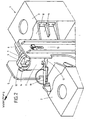
- FIG. 2 shows a spatial representation of an inventive rolling stand 1 with a left roll stand 2 and a right roll stand 3. These are connected at their upper ends by a Steraverse 4 together.
- a protruding upward from the Steraverse 4 piston rod 7 is slotted at its outer end 9 and receives a yoke 10. This, for example, with a bolt attached to the piston rod 7 yoke 10 is aligned in the rolling direction and engages with its ends in the support arms 5, 6 of a balancing device.
- a rotary sleeve is arranged, which is located on the surface 12 of a Balancierzylinders 22 (see FIG. 5 ) of the balancing device is supported.
- the yoke 10 is located with its lower edge 13 above the rotary sleeve. In rolling operation, as in FIG. 2 shown, the yoke 10 moves in a slot 14 of the rotary sleeve 11.
- the slot 14 is in FIG. 3 described in more detail.
- the rotary sleeve 11 is coupled to a hydraulic cylinder 19, which maintains the position shown in the rolling operation.
- the scaffold When changing the work roll, the scaffold is raised and the yoke 10 and the support arms 5, 6 supported thereon are moved vertically upwards. To lock this position, the rotary sleeve 11 is rotated by means of the hydraulic cylinder 19 about the vertical axis until a position is reached, in which the lower edge 13 of the yoke 10 on the support surface 18 (see FIG. 3 ) rests.
- the yoke When changing work rolls, the yoke is not placed on the rotary sleeve (surface 18), but held at a distance of about 10 mm above it. The position is approached by the mechanical adjustment and the support roller balancing balances the support roller against the employment.
- the rotating sleeve secures only to prevent falling of the support rollers and the support arms in the framework in case of failure of the hydraulic system (danger for maintenance personnel with removed work rolls). But it can also be, e.g. during maintenance / repair work for storage on the surface 18 come.
- the rotating sleeve thus not only serves for the safe storage of the yoke (back-up roller change), but also secures the approached position when changing work rolls with a certain distance.
- the yoke 10 can not go further down, the opening position for changing the work rolls is secured.
- the framework is raised further, the rotary sleeve 11 is further rotated by means of the hydraulic cylinder until the lower edge 13 of the yoke 10 rests on the upper annular surface 21 of the rotary sleeve 11 and this position is secured.
- the rotary sleeve 11 is again rotated to its original position, in which the yoke 10 can dip into the slot 14.
- FIG. 3 shows as a single part in a spatial representation of the rotary sleeve 11. This has axially a slot 14 into which the yoke 10 (not shown) is immersed.
- the yoke 10 moves vertically up to the support surface 16.
- the rotary sleeve is rotated and the yoke 10 settles on the support surface 18 from.
- the rotary sleeve 11 is further rotated and the yoke 10 settles on the upper annular surface 21 of the rotary sleeve 11 from.
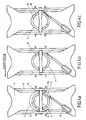
- FIG. 4 is shown in plan view the respective rotational position of the rotary sleeve 11.
- FIG. 4a The position during rolling operation shows FIG. 4a ,
- the rotary sleeve 11 is aligned in the rolling direction so that the yoke 10 can dip into the slot 14. That is, the yoke 10 moves freely in the slot 14.
- support surface 18 (see FIG. 3 to see).
- the rotary sleeve 11 is rotated by means of the hydraulic cylinder 19.
- the yoke 10, which has been moved all the way upwards, is used to lock onto the support surface 18 (see FIG FIG. 3 ) lowered.
- a backup roller change the rotary sleeve is rotated in a third switching position.
- This in Figure 4c illustrated step provides that the lower edge 13 of the yoke 10 comes to rest on the upper annular surface 21 of the rotary sleeve 11. Now both the support surface 16 and the support surface 18 can be seen from above.
- the rotary sleeve 11 By installing the hydraulic cylinder 19, the rotary sleeve 11 is held in each approached position. But it is also conceivable to use another drive for rotating the rotary sleeve 11. Furthermore, it is conceivable to provide further bearing surfaces for depositing the lower edge 13 of the yoke 10 in order to obtain further locking positions. Another embodiment of the rotary sleeve 11 is to form a slot 14 without shelf 18.
- FIG. 5 shows a longitudinal section through the rolling mill according to the invention. It is shown how the Balancierzylinder 22 is mounted in an opening of the St Sraverse 4.
Landscapes
- Engineering & Computer Science (AREA)
- Mechanical Engineering (AREA)
- Reduction Rolling/Reduction Stand/Operation Of Reduction Machine (AREA)
- Bending Of Plates, Rods, And Pipes (AREA)
- Spinning Or Twisting Of Yarns (AREA)
- Testing Of Balance (AREA)
- Investigating Or Analyzing Materials By The Use Of Magnetic Means (AREA)
- Handcart (AREA)
Description
- Die Erfindung betrifft ein Walzgerüst, insbesondere ein Grobblech - Walzgerüst nach dem Oberbegriff von Anspruch 1.
- Ein derartiges, bekanntes Walzgerüst ist beispielsweise in
Figur 1 dargestellt. Die Kolbenstange bewegt sich bei der Stützwalzenausbalancierung nach oben oder nach unten und bildet somit eine Anzeigevorrichtung, die die Position der Stützwalzenausbalancierung darstellt. - Aus
DE 101 16 988 A1 ist ein Walzgerüst mit Mitteln zum Anheben bzw. Absenken der Zwischenwalzen- bzw. Arbeitswalzenschienen beim Walzenwechsel bekannt. Dabei sind die mit Hilfe der Stützwalzen - Ausbalancierungszylinder den oberen Stützwalzensatz gegen die Hilfsanstellung ziehenden Stützwalzen - Ausbalancierungs -Traversen mit den jeweils oberen Walzenschienen durch Verbindungsstangen gekoppelt, derart, dass beim Anheben / Absenken der Stützwalzen - Ausbalancierungs - Traversen die Walzenschienen angehoben / abgesenkt werden. - Aus
DE 296 03 117 U1 ist ein Mehrwalzengerüst, insbesondere Sextowalzgerüst, bekannt, mit einer oberen und einer unteren Stützwalze, einer oberen und einer unteren Arbeitswalze und gegebenenfalls einer oberen und einer unteren Zwischenwalze, einer Einrichtung zum Ausbalancieren der Stützwalzen, Walzenbiegeeinrichtungen für die Arbeitswalzen und die Zwischenwalzen, Einrichtung zur gegenseitigen axialen Verschiebung der Arbeits- und / oder Zwischenwalzen sowie mit Einrichtungen für eine horizontale Parallelverschiebung der Arbeitswalzen oder Zwischenwalzen. Das Mehrwalzengerüst ist gekennzeichnet durch zwei in die Fenster der beiden Walzenständer des Walzengerüstes integrierte Funktionseinheiten mit je zwei symmetrisch und parallel zur Walzenachsenebene angeordneten, hydraulischen Stellzylinderpaaren, wobei jedes Stellzylinderpaar aus einem oberen Stellzylinder mit einem oberen, auf das Einbaustück der oberen Stützwalze wirkenden Stellkolben zum Ausbalancieren der oberen Stützwalze und einem unteren Stellzylinder mit einem unteren, auf das Einbaustück der unteren Stützwalze wirkenden Stellkolben zum Ausbalancieren der unteren Stützwalze besteht und die beiden Stellzylinder jedes Stellzylinderpaares koaxial in einem gemeinsamen Zylindergehäuse eingebaut sind. Das Zylindergehäuse ist durch einen Boden in zwei Zylinderkammern aufgeteilt, sowie auf den Stellzylindern der Stellzylinderpaare hydraulisch verschiebbare, doppeltwirkende, eine Biegung der Zwischenwalzen und der Arbeitswalzen bewirkende Stellhülsen, die mittels Nasen oder dergleichen an den Einbaustücken der Zwischenwalzen und der Arbeitswalzen angreifen. - Beim Auswechseln der Arbeits- und / oder Stützwalzen werden die jeweiligen Einbaustücke beispielsweise mittels Bolzen von einander weg bewegt, um einen Kontakt der jeweiligen Walzenoberflächen zu vermeiden. D.h. das Walzgerüst wird aufgefahren. Die dabei zu berücksichtigen Wege sind unterschiedlich, so dass die entsprechenden Einbaustücke und die Stützwalzenausbalancierung unterschiedliche Positionen im Ständerfenster bzw. im Walzgerüst einnehmen. Um diese Position einzuhalten, werden die Einrichtungen in dem Walzgerüst verriegelt.
- Die Verriegelungssysteme von Stützwalzen - Balancierungen sind zum Einen erforderlich, um bei Inspektionsarbeiten im Walzgerüst die obere Stützwalze bzw. die Stützwalzenbalancierungsarme mechanisch zu verriegeln. Somit wird eine Sicherheit für das Instandhaltungspersonal gegeben, welches sich bei aus dem Walzgerüst herausgefahrenen Arbeitswalzen im Walzgerüst befindet. Zum Anderen dient die Verriegelung dazu, bei einem Abfall des Hydraulikdrucks während des Arbeitswalzen- bzw. Stützwalzen-Wechsel und einem damit verbundenen Absinken der Balancierung eine definierte Position für das Wiedereinfahren der Walzen zu erhalten.
- Bei Grobblechgerüsten wird in einer Walzenwechselstellung die Stützwalzen-Balancierung mechanisch verriegelt. Dieses geschieht mittels vier Hydraulikzylindern, die Riegel unter den an oberen Haltearmen angebrachten Nasen schieben, auf denen sich die Haltearme ablegen können. Eine Sichtkontrolle der einwandfreien Funktion dieser Riegel ist nicht möglich, da sie von den Haltearmen verdeckt werden und nicht zugänglich sind. Die Belastbarkeit ist durch die Anbringung der Konsolen an der oberen Ständertraverse, in denen die Riegel verschoben werden, eingeschränkt.
- Bei Gerüsten mit hohem Aufgang unterscheiden sich aufgrund der fliegenden Biegung und den damit größeren Stützwalzen - Einbaustücken die Wechsel - Niveaus beim Arbeitswalzen - und beim Stützwalzenwechsel. Bei Gerüsten dieser Bauart wurde bisher nur eine der beiden Wechselniveaus mechanisch abgesichert. Dies bedeutet, in den anderen beiden Fällen eine erhebliche Sicherheitslücke, sollten die in den Wartungshandbüchem angegebene Vorschriften nicht eingehalten werden.
- Der Erfindung liegt daher die Aufgabe zugrunde, eine Stützwalzen - Verriegelung anzugeben, die unabhängig von dem Walzenaufgang ist und in beiden Wechselstellungen die Stützwalzen - Balancierung mechanisch verriegelt. Die Verriegelung sollte jederzeit gut zugänglich, optisch überwachbar und leicht zu warten sein.
- Diese Aufgabe wird erfindungsgemäß durch eine Vorrichtung mit den Merkmalen von Anspruch 1 in Kombination gelöst.
- Weitere Ausgestaltungen der Vorrichtung ergeben sich aus den diesbezüglichen Unteransprüchen.
- Ist der Verriegelungszylinder in Ausgangsstellung, taucht das die Haltearme tragende Joch in den tiefsten Schlitz der Drehhülse ein. Die Balancierung kann wie gewohnt alle möglichen Positionen anfahren, ohne jeglichen mechanischen Kontakt. Selbst die Position, bei der der Stützwalzen - Zylinder auf Block fährt, kann ohne Probleme eingestellt werden.
- Verriegelung der Stützwalzen - Balancierung beim Arbeitswalzenwechsel. Zu Beginn des Arbeitswalzenwechsels wird das Gerüst aufgefahren, d.h. die oberen Walzen werden angehoben und dadurch die Stützwalzen - Balancierung hochgefahren. Der Verriegelungszylinder dreht die Drehhülse in Stufe 1 Anschließend fährt die mechanische Anstellung auf das Arbeitswalzen - Wechselniveau. Die Stützwalzen - Balancierung folgt und legt das Joch auf der Drehhülse ab. Somit ist diese Position gesichert.
- Verriegelung der Stützwalzen - Balancierung beim Stützwalzenwechsel. Zu Beginn des Stützwalzenwechsels wird das Gerüst aufgefahren, d.h. die oberen Walzen werden angehoben und dadurch die Stützwalzen - Balancierung hochgefahren. Der Verriegelungszylinder dreht die Drehhülse in Stufe 2. Anschließend fährt die mechanische Anstellung auf das Stützwalzen - Wechselniveau. Die Stützwalzen - Balancierung folgt und legt das Joch auf der Drehhülse ab. Somit ist diese Position gesichert.
- Das erfindungsgemäße Verriegelungssystem ist sowohl für neue Gerüste als auch für die Nachrüstung von Altanlagen geeignet. Durch die individuelle Gestaltungsmöglichkeit der Drehhülse ist dieses System für alle Gerüste, unabhängig vom Walzenaufgang, einsetzbar.
- Die Vorteile des erfindungsgemäßen Verriegelungssystems sind:
- Hohe Sicherheit für Betreiberpersonal, da Absicherung des Gerüstbereichs bei den Walzenwechseln.
- Hohe Funktionssicherheit durch formschlüssige Kraftübertragung.
- Geringer Wartungsaufwand, da nur ein Verriegelungszylinder.
- Gute Wartungsbedingungen, da sehr gute Zugänglichkeit.
- Sicher verriegelter Zustand optisch sofort erkennbar.
- Elektrische Überwachung der jeweiligen Position.
- Universell einsetzbar für Vor - und Fertiggerüste.
- Nachrüstbar an vorhandene Anlagen.
- Ein Ausführungsbeispiel der Erfindung wird anhand sehr schematischer Zeichnungen näher beschrieben, wobei
- Fig. 1
- in teilweise geschnittener Seitenansicht ein zum Stand der Technik gehörendes Walzgerüst;
- Fig. 2
- in räumlicher Darstellung ein erfindungsgemäßes Walzgerüst;
- Fig. 3
- in räumlicher Darstellung eine Drehhülse als Einzelteil;
- Fig. 4
- in Draufsicht die Positionen der Drehhülse bei Walzbetrieb, Arbeitswalzenwechsel und Stützwalzenwechsel; und
- Fig. 5
- einen Längsschnitt durch das Walzgerüst mit der erfindungsgemäßen Ausbalanciervorrichtung
- In allen Figuren sind gleiche technische Merkmale mit gleichen Bezugszeichen versehen.
-
Figur 1 zeigt in teilweise geschnittener Seitenansicht ein zum Stand der Technik gehörendes Walzgerüst 1 mit Walzenständern 2, 3 und eine diese verbindende Ständertraverse 4. In der Ständertraverse 4 befindet sich eine Stützwalzenausbalancierung, deren Kolbenstange nach oben aus der Ständertraverse 4 herausragt. -
Figur 2 zeigt in räumlicher Darstellung ein erfindungsgemäßes Walzgerüst 1 mit einem linken Walzenständer 2 und einem rechten Walzenständer 3. Diese sind an ihren oberen Enden durch eine Ständertraverse 4 miteinander verbunden. Eine nach oben aus der Ständertraverse 4 herausragende Kolbenstange 7 ist an ihrem äußeren Ende 9 geschlitzt und nimmt ein Joch 10 auf. Dieses, beispielsweise mit einem Bolzen an der Kolbenstange 7 befestigte Joch 10 ist in Walzrichtung ausgerichtet und greift mit seinen Enden in die Haltearme 5, 6 einer Ausbalancierungsvorrichtung ein. Um die Kolbenstange 7 ist eine Drehhülse angeordnet, die sich auf der Oberfläche 12 eines Balancierzylinders 22 (sieheFigur 5 ) der Ausbalancierungsvorrichtung abstützt. Das Joch 10 befindet sich mit seiner Unterkante 13 oberhalb der Drehhülse. Beim Walzbetrieb, wie inFigur 2 dargestellt, bewegt sich das Joch 10 in einem Schlitz 14 der Drehhülse 11. Der Schlitz 14 ist inFigur 3 näher beschrieben. Die Drehhülse 11 ist mit einem Hydraulikzylinder 19 gekoppelt, der die gezeigte Position beim Walzbetrieb einhält. - Beim Arbeitswalzenwechsel wird das Gerüst aufgefahren und das Joch 10 und die darauf sich abstützenden Haltearme 5, 6 werden vertikal nach oben verfahren. Zur Verriegelung dieser Position wird die Drehhülse 11 mittels des Hydraulikzylinders 19 um die vertikale Achse verdreht bis eine Position erreicht wird, in der die Unterkante 13 des Jochs 10 auf der Ablagefläche 18 (siehe
Figur 3 ) aufliegt. - Beim Arbeitswalzen-Wechsel wird das Joch nicht auf der Drehhülse abgelegt (Fläche 18), sondern in einem Abstand von ca. 10 mm darüber gehalten. Die Position wird von der mechanischen Anstellung angefahren und die Stützwalzen-Balancierung balanciert die Stützwalze gegen die Anstellung. Die Drehhülse sichert nur ab, um bei einem Ausfall des Hydrauliksystems ein Herabstürzen der Stützwalzen und der Tragarme im Gerüst zu verhindern (Gefahr für Wartungspersonal bei ausgebauten Arbeitswalzen). Es kann aber auch, z.B. bei Instandhaltungs- / Reparaturarbeiten zur Ablage auf der Fläche 18 kommen. Die Drehhülse dient also nicht nur zur sicheren Ablage des Jochs (Stützwalzen-Wechsel), sondern sichert auch mit gewissen Abstand die angefahrene Position beim Arbeitswalzen-Wechsel. Das Joch 10 kann nicht weiter nach unten gelangen, die Öffnungsposition zum Wechseln der Arbeitswalzen ist gesichert.
- Werden in einem weiteren Schritt die Stützwalzen gewechselt, so wird das Gerüst weiter aufgefahren, die Drehhülse 11 mittels des Hydraulikzylinders weiter verdreht, bis die Unterkante 13 des Jochs 10 auf der oberen Ringfläche 21 der Drehhülse 11 aufliegt und diese Position gesichert ist.
Nach dem Wechsel der Arbeits - und / oder Stützwalzen wird die Drehhülse 11 wieder in ihre Ausgangsposition verdreht, in der das Joch 10 in den Schlitz 14 eintauchen kann. -
Figur 3 zeigt als Einzelteil in räumlicher Darstellung die Drehhülse 11. Diese weist axial einen Schlitz 14 auf, in die das Joch 10 (nicht dargestellt) eintaucht. Zum Walzbetrieb des Walzgerüstes 1 bewegt sich das Joch 10 vertikal bis zur Ablagefläche 16. Beim Arbeitswalzenwechsel wird die Drehhülse verdreht und das Joch 10 legt sich auf die Ablagefläche 18 ab. Beim Stützwalzenwechsel wird die Drehhülse 11 weiter verdreht und das Joch 10 legt sich auf der oberen Ringfläche 21 der Drehhülse 11 ab. - In
Figur 4 ist in Draufsicht die jeweilige Verdrehposition der Drehhülse 11 dargestellt. - Die Position bei Walzbetrieb zeigt
Figur 4a . Die Drehhülse 11 ist in Walzrichtung so ausgerichtet, dass das Joch 10 in den Schlitz 14 eintauchen kann. D.h. das Joch 10 bewegt sich frei im Schlitz 14. In dieser Ansicht ist Auflagefläche 18 (sieheFigur 3 ) zu sehen.
Werden die Arbeitswalzen gewechselt, wie inFigur 4b zu sehen, so wird die Drehhülse 11 mittels des Hydraulikzylinders 19 verdreht. Das zuvor ganz nach oben gefahrene Joch 10 wird zum Verriegeln auf die Auflagefläche 18 (sieheFigur 3 ) abgesenkt. Jetzt ist von oben die Auflagefläche 16 (sieheFigur 3 ) zu sehen.
Bei einem Stützwalzenwechsel wird die Drehhülse in eine dritte Schaltstellung verdreht. Dieser inFigur 4c dargestellte Arbeitsschritt sieht vor, dass die Unterkante 13 des Jochs 10 auf der oberen Ringfläche 21 der Drehhülse 11 zur Auflage kommt. Jetzt sind von oben sowohl die Auflagefläche 16 als auch die Auflagefläche 18 zu sehen. - Durch den Einbau des Hydraulikzylinders 19 wird die Drehhülse 11 in der jeweils angefahrenen Stellung gehalten. Es ist aber auch denkbar, einen anderen Antrieb zum Verdrehen der Drehhülse 11 zu verwenden. Weiterhin ist denkbar, weitere Auflageflächen zur Ablage der Unterkante 13 des Jochs 10 vorzusehen, um weiterer Verriegelungspositionen zu erhalten. Eine andere Ausführung der Drehhülse 11 besteht darin, einen Schlitz 14 ohne Ablagefläche 18 auszubilden.
-
Figur 5 zeigt einen Längsschnitt durch das erfindungsgemäße Walzgerüst. Es ist gezeigt, wie der Balancierzylinder 22 in eine Öffnung der Ständertraverse 4 eingehangen ist. -
- 1
- Walzgerüst
- 2
- linker Walzenständer
- 3
- rechter Walzenständer
- 4
- Ständertraverse
- 5
- Haltearm
- 6
- Haltearm
- 7
- Kolbenstange
- 8
- obere Fläche
- 9
- äußeres Ende
- 10
- Joch
- 11
- Drehhülse
- 12
- Oberkante
- 13
- Unterkante
- 14
- Schlitz
- 15
- Absatz
- 16
- Auflagefläche
- 17
- Absatz
- 18
- Auflagefläche
- 19
- Hydraulikzylinder
- 20
- Einführschrägen
- 21
- obere Ringfläche
- 22
- Balancierzylinder
Claims (3)
- Walzgerüst (1), insbesondere ein Grobblech - Walzgerüst, mit einem rechten Gerüstständer (2), einem linken Gerüstständer (3), einer diese verbindenden obere Ständertraverse (4), mindestens einem Arbeitswalzenpaar und einem Stützwalzenpaar sowie dazugehörenden Einbaustücken, sowie einer Ausbalancierungsvorrichtung, welche Haltearme (5, 6) und einen Balancierzylinder (22) aufweist, der mit seiner Oberkante (12) in Form eines Kragens in eine Öffnung in der Ständertraverse (4) eingehangen ist, und mit einer durch die Ständertraverse (4) nach oben ragenden Kolbenstange (7), die über die obere Fläche (8) der Ständertraverse (4) hinausragt.
dadurch gekennzeichnet,
dass die Kolbenstange (7) an ihrem äußeren Ende (9) ein Joch (10) aufweist, das in Walzrichtung ausgerichtet ist und in die Haltearme (5, 6) der Ausbalancierungsvorrichtung eingreift, sowie eine die Kolbenstange (7) umschließende Drehhülse (11), die zwischen der Oberkante (12) des Balancierzylinders (22) und der Unterkante (13) des Jochs (10) angeordnet ist und sich dabei auf der Ständertraverse (4) abstützt und mindestens einen durchgängigen Schlitz (14) aufweist, in den das Joch (10) eintauchen kann; dass der Schlitz (14) einen ersten Absatz (15) mit einer Auflagefläche (16) aufweist;
dass der Schlitz (14) einen zweiten Absatz (17) mit einer zweiten Auflagefläche (18) aufweist; und
dass die Drehhülse (11) mit einem Hydraulikzylinder (19) oder mit einem Elektromotor verbunden ausgebildet ist. - Walzgerüst nach Anspruch 1,
dadurch gekennzeichnet,
dass zwischen der Drehhülse (11) und der Oberkante (12) des Balancierzylinders ein Drucklager angeordnet ist. - Walzgerüst nach Anspruch 1 oder 2,
dadurch gekennzeichnet,
dass der Schlitz (14) mit Einführschrägen (20) ausgebildet sind.
Applications Claiming Priority (2)
| Application Number | Priority Date | Filing Date | Title |
|---|---|---|---|
| DE102006032813A DE102006032813A1 (de) | 2006-07-14 | 2006-07-14 | Vorrichtung zur Drehverriegelung der Stützwalzenbalancierung von Walzgerüsten |
| PCT/EP2007/006165 WO2008006571A1 (de) | 2006-07-14 | 2007-07-11 | Vorrichtung zur drehverriegelung der stützwalzenbalancierung von walzgerüsten |
Publications (2)
| Publication Number | Publication Date |
|---|---|
| EP1907143A1 EP1907143A1 (de) | 2008-04-09 |
| EP1907143B1 true EP1907143B1 (de) | 2009-12-16 |
Family
ID=38438683
Family Applications (1)
| Application Number | Title | Priority Date | Filing Date |
|---|---|---|---|
| EP07765182A Active EP1907143B1 (de) | 2006-07-14 | 2007-07-11 | Vorrichtung zur drehverriegelung der stützwalzenbalancierung von walzgerüsten |
Country Status (9)
| Country | Link |
|---|---|
| US (1) | US8042371B2 (de) |
| EP (1) | EP1907143B1 (de) |
| JP (1) | JP4937275B2 (de) |
| CN (1) | CN101346195B (de) |
| AT (1) | ATE451979T1 (de) |
| DE (2) | DE102006032813A1 (de) |
| RU (1) | RU2372161C1 (de) |
| UA (1) | UA90913C2 (de) |
| WO (1) | WO2008006571A1 (de) |
Cited By (2)
| Publication number | Priority date | Publication date | Assignee | Title |
|---|---|---|---|---|
| CN101745539B (zh) * | 2009-12-29 | 2011-11-30 | 太原重工股份有限公司 | 一种轧管机机盖的打开装置 |
| WO2020173614A1 (de) | 2019-02-28 | 2020-09-03 | Sms Group Gmbh | Walzgerüst zum walzen metallischen guts |
Families Citing this family (3)
| Publication number | Priority date | Publication date | Assignee | Title |
|---|---|---|---|---|
| DE102009058876A1 (de) * | 2009-01-23 | 2010-07-29 | Sms Siemag Ag | Biege- und Ausbalanciervorrichtung für axial verschiebbare Arbeitswalzen eines Walzgerüstes |
| CN107350292B (zh) * | 2017-08-31 | 2023-09-12 | 马鞍山市新华异型钢开发有限责任公司 | 一种轧机传动轴平衡装置 |
| DE102019210273A1 (de) | 2018-10-12 | 2020-04-16 | Sms Group Gmbh | Walzgerüst zum Walzen eines metallischen Breitflachprodukts |
Citations (8)
| Publication number | Priority date | Publication date | Assignee | Title |
|---|---|---|---|---|
| JPS58172507A (ja) * | 1982-04-05 | 1983-10-11 | Nippon Kokan Kk <Nkk> | 管外面の異常形状検出装置 |
| JPH0484624A (ja) * | 1990-07-27 | 1992-03-17 | Nkk Corp | マンドレルミルにおける被圧延材穴明発生判定方法 |
| JPH07246414A (ja) * | 1994-03-10 | 1995-09-26 | Nkk Corp | ストレッチレデューサーの管端部肉厚制御方法 |
| JPH0871616A (ja) * | 1994-09-01 | 1996-03-19 | Sumitomo Metal Ind Ltd | 継目無管の圧延装置および圧延制御方法 |
| JP2001293503A (ja) * | 2000-04-13 | 2001-10-23 | Sumitomo Metal Ind Ltd | 継ぎ目無し管の圧延装置および圧延制御方法 |
| JP2002035817A (ja) * | 2000-07-27 | 2002-02-05 | Sumitomo Metal Ind Ltd | 継目無鋼管製造ラインで用いられる圧延制御方法 |
| JP2003220403A (ja) * | 2002-01-28 | 2003-08-05 | Sumitomo Metal Ind Ltd | 継目無鋼管の製造方法 |
| JP2004337941A (ja) * | 2003-05-16 | 2004-12-02 | Sumitomo Metal Ind Ltd | 金属管製造装置および金属管の肉厚制御方法 |
Family Cites Families (13)
| Publication number | Priority date | Publication date | Assignee | Title |
|---|---|---|---|---|
| GB1036821A (en) * | 1962-06-01 | 1966-07-20 | United Eng Foundry Co | Apparatus for automatically positioning a roll in a rolling mill |
| JPS496751B1 (de) * | 1970-11-30 | 1974-02-15 | ||
| US3702557A (en) * | 1971-03-01 | 1972-11-14 | Wean United Inc | Apparatus for supporting yokes for a rolling mill having roll contour control |
| LU66380A1 (de) * | 1971-10-28 | 1973-01-23 | ||
| JPS5320943B2 (de) * | 1973-08-29 | 1978-06-29 | ||
| US4453393A (en) * | 1981-08-13 | 1984-06-12 | Mitsubishi Jukogyo Kabushiki Kaisha | Four high mill of the paired-roll-crossing type |
| JPS59118209A (ja) * | 1982-12-27 | 1984-07-07 | Mitsubishi Heavy Ind Ltd | ロ−ルクロス圧延機のトツプロ−ルバランス装置 |
| US4706484A (en) * | 1986-07-28 | 1987-11-17 | United Engineering Rolling Mills, Inc. | Universal rolling mill |
| JPS6390508A (ja) * | 1986-10-03 | 1988-04-21 | Kansai Paint Co Ltd | ソ−プフリ−カチオン性エマルシヨンの製造方法 |
| DE4417274C2 (de) * | 1994-05-18 | 2003-04-17 | Sms Demag Ag | Verfahren zum Betreiben eines Walzgerüstes |
| US5842368A (en) * | 1996-02-23 | 1998-12-01 | Achenbach Buschhutten Gmbh | Multiroll stand |
| DE29603117U1 (de) * | 1996-02-23 | 1996-04-11 | Achenbach Buschhütten GmbH, 57223 Kreuztal | Mehrwalzengerüst |
| DE10116988B4 (de) * | 2001-04-05 | 2012-03-15 | Sms Siemag Aktiengesellschaft | Walzgerüst |
-
2006
- 2006-07-14 DE DE102006032813A patent/DE102006032813A1/de not_active Withdrawn
-
2007
- 2007-07-11 EP EP07765182A patent/EP1907143B1/de active Active
- 2007-07-11 AT AT07765182T patent/ATE451979T1/de active
- 2007-07-11 RU RU2008110586/02A patent/RU2372161C1/ru active
- 2007-07-11 DE DE502007002321T patent/DE502007002321D1/de active Active
- 2007-07-11 WO PCT/EP2007/006165 patent/WO2008006571A1/de not_active Ceased
- 2007-07-11 JP JP2008547983A patent/JP4937275B2/ja not_active Expired - Fee Related
- 2007-07-11 US US12/309,389 patent/US8042371B2/en active Active
- 2007-07-11 CN CN2007800009659A patent/CN101346195B/zh active Active
- 2007-11-07 UA UAA200803549A patent/UA90913C2/ru unknown
Patent Citations (9)
| Publication number | Priority date | Publication date | Assignee | Title |
|---|---|---|---|---|
| JPS58172507A (ja) * | 1982-04-05 | 1983-10-11 | Nippon Kokan Kk <Nkk> | 管外面の異常形状検出装置 |
| JPH0484624A (ja) * | 1990-07-27 | 1992-03-17 | Nkk Corp | マンドレルミルにおける被圧延材穴明発生判定方法 |
| JPH07246414A (ja) * | 1994-03-10 | 1995-09-26 | Nkk Corp | ストレッチレデューサーの管端部肉厚制御方法 |
| JPH0871616A (ja) * | 1994-09-01 | 1996-03-19 | Sumitomo Metal Ind Ltd | 継目無管の圧延装置および圧延制御方法 |
| JP2001293503A (ja) * | 2000-04-13 | 2001-10-23 | Sumitomo Metal Ind Ltd | 継ぎ目無し管の圧延装置および圧延制御方法 |
| JP2002035817A (ja) * | 2000-07-27 | 2002-02-05 | Sumitomo Metal Ind Ltd | 継目無鋼管製造ラインで用いられる圧延制御方法 |
| JP2003220403A (ja) * | 2002-01-28 | 2003-08-05 | Sumitomo Metal Ind Ltd | 継目無鋼管の製造方法 |
| US20040065133A1 (en) * | 2002-01-28 | 2004-04-08 | Kenichi Sasaki | Method of producing seamless steel tubes |
| JP2004337941A (ja) * | 2003-05-16 | 2004-12-02 | Sumitomo Metal Ind Ltd | 金属管製造装置および金属管の肉厚制御方法 |
Cited By (3)
| Publication number | Priority date | Publication date | Assignee | Title |
|---|---|---|---|---|
| CN101745539B (zh) * | 2009-12-29 | 2011-11-30 | 太原重工股份有限公司 | 一种轧管机机盖的打开装置 |
| WO2020173614A1 (de) | 2019-02-28 | 2020-09-03 | Sms Group Gmbh | Walzgerüst zum walzen metallischen guts |
| US11779973B2 (en) | 2019-02-28 | 2023-10-10 | Sms Group Gmbh | Rolling mill for rolling metal products |
Also Published As
| Publication number | Publication date |
|---|---|
| EP1907143A1 (de) | 2008-04-09 |
| WO2008006571A1 (de) | 2008-01-17 |
| US8042371B2 (en) | 2011-10-25 |
| RU2372161C1 (ru) | 2009-11-10 |
| RU2008110586A (ru) | 2009-09-27 |
| DE102006032813A1 (de) | 2008-01-24 |
| DE502007002321D1 (de) | 2010-01-28 |
| JP4937275B2 (ja) | 2012-05-23 |
| ATE451979T1 (de) | 2010-01-15 |
| CN101346195A (zh) | 2009-01-14 |
| JP2009522107A (ja) | 2009-06-11 |
| UA90913C2 (en) | 2010-06-10 |
| US20090199611A1 (en) | 2009-08-13 |
| CN101346195B (zh) | 2010-06-09 |
Similar Documents
| Publication | Publication Date | Title |
|---|---|---|
| EP1951452B1 (de) | Verfahren und einrichtung zum wechseln von walzen | |
| EP3352923B1 (de) | Walzgerüst und verfahren zum wechseln von arbeitswalzen | |
| EP1507606B1 (de) | Verfahren und vorrichtung zum wechseln von arbeitswalzenpaaren und/ oder stützwalzenpaaren an walzgerüsten | |
| EP2753437B1 (de) | Kombinierte walzenverriegelung/ antriebsspindelhalterung für walzanlagen | |
| WO2008006571A1 (de) | Vorrichtung zur drehverriegelung der stützwalzenbalancierung von walzgerüsten | |
| DE3420737A1 (de) | Zusatzeinrichtung fuer hoehenverstellbare arbeitsgerueste | |
| DE60203128T2 (de) | Universalwalzgerüst mit walzspaltregelung | |
| EP2190601A1 (de) | VORRICHTUNG ZUR VERSTELLUNG DES ABSTANDES DER ABSTREIFERMEIßEL | |
| EP3590616B1 (de) | Verfahren und vorrichtung zum wechseln von stützwalzen an einem walzgerüst | |
| DE10116988B4 (de) | Walzgerüst | |
| DE2003166A1 (de) | Einrichtung zum Walzenwechsel bei Walzwerken | |
| DE2654768A1 (de) | Walzenwechselvorrichtung | |
| EP1732715B1 (de) | Einschubverfahren von maschineneinheiten in eine produktionslinie | |
| DE2056429B2 (de) | Ortsbewegliche vorrichtung zum untergreifen und anschliessenden heben von lasten | |
| EP0329998B1 (de) | Walzstrasse, insbesondere Walzstrasse in einem Formstahl-Walzwerk | |
| EP0597265B1 (de) | Walzgerüst | |
| EP0483599A2 (de) | Walzgerüst mit Anordnungen zur distanzierten Abstützung der oberen Arbeitswalze | |
| EP0256410A2 (de) | Biege- und Ausbalanciervorrichtung für axial verschiebbare Arbeitswalzen eines Quartowalzgerüstes | |
| DE1954460C3 (de) | Abstandshalteeinrichtung an einem Walzgerüst mit auswechselbaren Abstandswalzen | |
| DE3211378A1 (de) | Walzenstuetzeinrichtung fuer den arbeitswalzenwechsel an walzgeruesten | |
| EP3906122B1 (de) | Walzvorrichtung | |
| DE3902889C2 (de) | Offene Walzstraße mit nebeneinander angeordneten Walzgerüsten | |
| DE19633309B4 (de) | Vorrichtung zur Axialverriegelung der, auf Gleitflächen der Fenster der Ständer von Walzgerüsten anstellgeführten Lagereinbaustücke von Walzen | |
| DE3019052C2 (de) | Vorrichtung zum Auswechseln der Arbeitswalzen von Walzgerüsten | |
| DE8900944U1 (de) | Hebebühne für Kraftfahrzeuge |
Legal Events
| Date | Code | Title | Description |
|---|---|---|---|
| PUAI | Public reference made under article 153(3) epc to a published international application that has entered the european phase |
Free format text: ORIGINAL CODE: 0009012 |
|
| 17P | Request for examination filed |
Effective date: 20080108 |
|
| AK | Designated contracting states |
Kind code of ref document: A1 Designated state(s): AT BE BG CH CY CZ DE DK EE ES FI FR GB GR HU IE IS IT LI LT LU LV MC MT NL PL PT RO SE SI SK TR |
|
| AX | Request for extension of the european patent |
Extension state: AL BA HR MK RS |
|
| 17Q | First examination report despatched |
Effective date: 20080612 |
|
| RAP1 | Party data changed (applicant data changed or rights of an application transferred) |
Owner name: SMS SIEMAG AG |
|
| GRAP | Despatch of communication of intention to grant a patent |
Free format text: ORIGINAL CODE: EPIDOSNIGR1 |
|
| GRAC | Information related to communication of intention to grant a patent modified |
Free format text: ORIGINAL CODE: EPIDOSCIGR1 |
|
| DAX | Request for extension of the european patent (deleted) | ||
| GRAS | Grant fee paid |
Free format text: ORIGINAL CODE: EPIDOSNIGR3 |
|
| GRAA | (expected) grant |
Free format text: ORIGINAL CODE: 0009210 |
|
| AK | Designated contracting states |
Kind code of ref document: B1 Designated state(s): AT BE BG CH CY CZ DE DK EE ES FI FR GB GR HU IE IS IT LI LT LU LV MC MT NL PL PT RO SE SI SK TR |
|
| REG | Reference to a national code |
Ref country code: GB Ref legal event code: FG4D Free format text: NOT ENGLISH |
|
| REG | Reference to a national code |
Ref country code: CH Ref legal event code: EP |
|
| REG | Reference to a national code |
Ref country code: IE Ref legal event code: FG4D |
|
| REF | Corresponds to: |
Ref document number: 502007002321 Country of ref document: DE Date of ref document: 20100128 Kind code of ref document: P |
|
| REG | Reference to a national code |
Ref country code: NL Ref legal event code: VDEP Effective date: 20091216 |
|
| PG25 | Lapsed in a contracting state [announced via postgrant information from national office to epo] |
Ref country code: SE Free format text: LAPSE BECAUSE OF FAILURE TO SUBMIT A TRANSLATION OF THE DESCRIPTION OR TO PAY THE FEE WITHIN THE PRESCRIBED TIME-LIMIT Effective date: 20091216 Ref country code: LT Free format text: LAPSE BECAUSE OF FAILURE TO SUBMIT A TRANSLATION OF THE DESCRIPTION OR TO PAY THE FEE WITHIN THE PRESCRIBED TIME-LIMIT Effective date: 20091216 Ref country code: FI Free format text: LAPSE BECAUSE OF FAILURE TO SUBMIT A TRANSLATION OF THE DESCRIPTION OR TO PAY THE FEE WITHIN THE PRESCRIBED TIME-LIMIT Effective date: 20091216 |
|
| LTIE | Lt: invalidation of european patent or patent extension |
Effective date: 20091216 |
|
| PG25 | Lapsed in a contracting state [announced via postgrant information from national office to epo] |
Ref country code: LV Free format text: LAPSE BECAUSE OF FAILURE TO SUBMIT A TRANSLATION OF THE DESCRIPTION OR TO PAY THE FEE WITHIN THE PRESCRIBED TIME-LIMIT Effective date: 20091216 Ref country code: PL Free format text: LAPSE BECAUSE OF FAILURE TO SUBMIT A TRANSLATION OF THE DESCRIPTION OR TO PAY THE FEE WITHIN THE PRESCRIBED TIME-LIMIT Effective date: 20091216 Ref country code: SI Free format text: LAPSE BECAUSE OF FAILURE TO SUBMIT A TRANSLATION OF THE DESCRIPTION OR TO PAY THE FEE WITHIN THE PRESCRIBED TIME-LIMIT Effective date: 20091216 |
|
| REG | Reference to a national code |
Ref country code: IE Ref legal event code: FD4D |
|
| PG25 | Lapsed in a contracting state [announced via postgrant information from national office to epo] |
Ref country code: BG Free format text: LAPSE BECAUSE OF FAILURE TO SUBMIT A TRANSLATION OF THE DESCRIPTION OR TO PAY THE FEE WITHIN THE PRESCRIBED TIME-LIMIT Effective date: 20100316 Ref country code: EE Free format text: LAPSE BECAUSE OF FAILURE TO SUBMIT A TRANSLATION OF THE DESCRIPTION OR TO PAY THE FEE WITHIN THE PRESCRIBED TIME-LIMIT Effective date: 20091216 Ref country code: PT Free format text: LAPSE BECAUSE OF FAILURE TO SUBMIT A TRANSLATION OF THE DESCRIPTION OR TO PAY THE FEE WITHIN THE PRESCRIBED TIME-LIMIT Effective date: 20100416 Ref country code: NL Free format text: LAPSE BECAUSE OF FAILURE TO SUBMIT A TRANSLATION OF THE DESCRIPTION OR TO PAY THE FEE WITHIN THE PRESCRIBED TIME-LIMIT Effective date: 20091216 Ref country code: RO Free format text: LAPSE BECAUSE OF FAILURE TO SUBMIT A TRANSLATION OF THE DESCRIPTION OR TO PAY THE FEE WITHIN THE PRESCRIBED TIME-LIMIT Effective date: 20091216 Ref country code: ES Free format text: LAPSE BECAUSE OF FAILURE TO SUBMIT A TRANSLATION OF THE DESCRIPTION OR TO PAY THE FEE WITHIN THE PRESCRIBED TIME-LIMIT Effective date: 20100327 Ref country code: IE Free format text: LAPSE BECAUSE OF FAILURE TO SUBMIT A TRANSLATION OF THE DESCRIPTION OR TO PAY THE FEE WITHIN THE PRESCRIBED TIME-LIMIT Effective date: 20091216 Ref country code: IS Free format text: LAPSE BECAUSE OF FAILURE TO SUBMIT A TRANSLATION OF THE DESCRIPTION OR TO PAY THE FEE WITHIN THE PRESCRIBED TIME-LIMIT Effective date: 20100416 |
|
| PG25 | Lapsed in a contracting state [announced via postgrant information from national office to epo] |
Ref country code: SK Free format text: LAPSE BECAUSE OF FAILURE TO SUBMIT A TRANSLATION OF THE DESCRIPTION OR TO PAY THE FEE WITHIN THE PRESCRIBED TIME-LIMIT Effective date: 20091216 |
|
| PLBE | No opposition filed within time limit |
Free format text: ORIGINAL CODE: 0009261 |
|
| STAA | Information on the status of an ep patent application or granted ep patent |
Free format text: STATUS: NO OPPOSITION FILED WITHIN TIME LIMIT |
|
| PG25 | Lapsed in a contracting state [announced via postgrant information from national office to epo] |
Ref country code: CY Free format text: LAPSE BECAUSE OF FAILURE TO SUBMIT A TRANSLATION OF THE DESCRIPTION OR TO PAY THE FEE WITHIN THE PRESCRIBED TIME-LIMIT Effective date: 20091216 Ref country code: GR Free format text: LAPSE BECAUSE OF FAILURE TO SUBMIT A TRANSLATION OF THE DESCRIPTION OR TO PAY THE FEE WITHIN THE PRESCRIBED TIME-LIMIT Effective date: 20100317 |
|
| 26N | No opposition filed |
Effective date: 20100917 |
|
| BERE | Be: lapsed |
Owner name: SMS SIEMAG AG Effective date: 20100731 |
|
| PG25 | Lapsed in a contracting state [announced via postgrant information from national office to epo] |
Ref country code: DK Free format text: LAPSE BECAUSE OF FAILURE TO SUBMIT A TRANSLATION OF THE DESCRIPTION OR TO PAY THE FEE WITHIN THE PRESCRIBED TIME-LIMIT Effective date: 20091216 |
|
| PG25 | Lapsed in a contracting state [announced via postgrant information from national office to epo] |
Ref country code: MC Free format text: LAPSE BECAUSE OF NON-PAYMENT OF DUE FEES Effective date: 20100731 |
|
| PG25 | Lapsed in a contracting state [announced via postgrant information from national office to epo] |
Ref country code: BE Free format text: LAPSE BECAUSE OF NON-PAYMENT OF DUE FEES Effective date: 20100731 |
|
| PG25 | Lapsed in a contracting state [announced via postgrant information from national office to epo] |
Ref country code: MT Free format text: LAPSE BECAUSE OF FAILURE TO SUBMIT A TRANSLATION OF THE DESCRIPTION OR TO PAY THE FEE WITHIN THE PRESCRIBED TIME-LIMIT Effective date: 20091216 |
|
| REG | Reference to a national code |
Ref country code: CH Ref legal event code: PL |
|
| PG25 | Lapsed in a contracting state [announced via postgrant information from national office to epo] |
Ref country code: LI Free format text: LAPSE BECAUSE OF NON-PAYMENT OF DUE FEES Effective date: 20110731 Ref country code: CH Free format text: LAPSE BECAUSE OF NON-PAYMENT OF DUE FEES Effective date: 20110731 |
|
| PG25 | Lapsed in a contracting state [announced via postgrant information from national office to epo] |
Ref country code: HU Free format text: LAPSE BECAUSE OF FAILURE TO SUBMIT A TRANSLATION OF THE DESCRIPTION OR TO PAY THE FEE WITHIN THE PRESCRIBED TIME-LIMIT Effective date: 20100617 Ref country code: LU Free format text: LAPSE BECAUSE OF NON-PAYMENT OF DUE FEES Effective date: 20100711 |
|
| PG25 | Lapsed in a contracting state [announced via postgrant information from national office to epo] |
Ref country code: TR Free format text: LAPSE BECAUSE OF FAILURE TO SUBMIT A TRANSLATION OF THE DESCRIPTION OR TO PAY THE FEE WITHIN THE PRESCRIBED TIME-LIMIT Effective date: 20091216 |
|
| REG | Reference to a national code |
Ref country code: DE Ref legal event code: R082 Ref document number: 502007002321 Country of ref document: DE Representative=s name: HEMMERICH & KOLLEGEN, DE Ref country code: DE Ref legal event code: R081 Ref document number: 502007002321 Country of ref document: DE Owner name: SMS GROUP GMBH, DE Free format text: FORMER OWNER: SMS SIEMAG AG, 40237 DUESSELDORF, DE |
|
| REG | Reference to a national code |
Ref country code: FR Ref legal event code: PLFP Year of fee payment: 10 |
|
| REG | Reference to a national code |
Ref country code: FR Ref legal event code: PLFP Year of fee payment: 11 |
|
| REG | Reference to a national code |
Ref country code: FR Ref legal event code: PLFP Year of fee payment: 12 |
|
| P01 | Opt-out of the competence of the unified patent court (upc) registered |
Effective date: 20230707 |
|
| PGFP | Annual fee paid to national office [announced via postgrant information from national office to epo] |
Ref country code: DE Payment date: 20240719 Year of fee payment: 18 |
|
| PGFP | Annual fee paid to national office [announced via postgrant information from national office to epo] |
Ref country code: GB Payment date: 20240722 Year of fee payment: 18 |
|
| PGFP | Annual fee paid to national office [announced via postgrant information from national office to epo] |
Ref country code: FR Payment date: 20240729 Year of fee payment: 18 |
|
| PGFP | Annual fee paid to national office [announced via postgrant information from national office to epo] |
Ref country code: CZ Payment date: 20240628 Year of fee payment: 18 |
|
| PGFP | Annual fee paid to national office [announced via postgrant information from national office to epo] |
Ref country code: AT Payment date: 20240722 Year of fee payment: 18 |
|
| PGFP | Annual fee paid to national office [announced via postgrant information from national office to epo] |
Ref country code: IT Payment date: 20240725 Year of fee payment: 18 |
|
| PG25 | Lapsed in a contracting state [announced via postgrant information from national office to epo] |
Ref country code: CZ Free format text: LAPSE BECAUSE OF NON-PAYMENT OF DUE FEES Effective date: 20250711 |
|
| REG | Reference to a national code |
Ref country code: DE Ref legal event code: R119 Ref document number: 502007002321 Country of ref document: DE |
|
| REG | Reference to a national code |
Ref country code: AT Ref legal event code: MM01 Ref document number: 451979 Country of ref document: AT Kind code of ref document: T Effective date: 20250711 |
|
| GBPC | Gb: european patent ceased through non-payment of renewal fee |
Effective date: 20250711 |
|
| PG25 | Lapsed in a contracting state [announced via postgrant information from national office to epo] |
Ref country code: GB Free format text: LAPSE BECAUSE OF NON-PAYMENT OF DUE FEES Effective date: 20250711 |
|
| PG25 | Lapsed in a contracting state [announced via postgrant information from national office to epo] |
Ref country code: DE Free format text: LAPSE BECAUSE OF NON-PAYMENT OF DUE FEES Effective date: 20260203 |
|
| PG25 | Lapsed in a contracting state [announced via postgrant information from national office to epo] |
Ref country code: AT Free format text: LAPSE BECAUSE OF NON-PAYMENT OF DUE FEES Effective date: 20250711 |
|
| PG25 | Lapsed in a contracting state [announced via postgrant information from national office to epo] |
Ref country code: FR Free format text: LAPSE BECAUSE OF NON-PAYMENT OF DUE FEES Effective date: 20250731 |