EP1907149B1 - Universalpresse zur deformierung von rohrverbindungshülsen und für andere einsätze - Google Patents
Universalpresse zur deformierung von rohrverbindungshülsen und für andere einsätze Download PDFInfo
- Publication number
- EP1907149B1 EP1907149B1 EP06762569A EP06762569A EP1907149B1 EP 1907149 B1 EP1907149 B1 EP 1907149B1 EP 06762569 A EP06762569 A EP 06762569A EP 06762569 A EP06762569 A EP 06762569A EP 1907149 B1 EP1907149 B1 EP 1907149B1
- Authority
- EP
- European Patent Office
- Prior art keywords
- press
- crosspiece
- crosspieces
- crimping
- movement
- Prior art date
- Legal status (The legal status is an assumption and is not a legal conclusion. Google has not performed a legal analysis and makes no representation as to the accuracy of the status listed.)
- Not-in-force
Links
- 238000002788 crimping Methods 0.000 claims abstract description 43
- 125000006850 spacer group Chemical group 0.000 claims description 12
- 230000002787 reinforcement Effects 0.000 claims description 7
- 230000002829 reductive effect Effects 0.000 claims description 4
- 230000000717 retained effect Effects 0.000 claims description 4
- 238000003780 insertion Methods 0.000 claims 3
- 230000037431 insertion Effects 0.000 claims 3
- 230000014759 maintenance of location Effects 0.000 claims 2
- 239000012530 fluid Substances 0.000 claims 1
- 239000002184 metal Substances 0.000 description 6
- 239000000463 material Substances 0.000 description 2
- 230000001419 dependent effect Effects 0.000 description 1
- 239000013013 elastic material Substances 0.000 description 1
- 230000000670 limiting effect Effects 0.000 description 1
- 238000012986 modification Methods 0.000 description 1
- 230000004048 modification Effects 0.000 description 1
- 230000036961 partial effect Effects 0.000 description 1
- 230000000284 resting effect Effects 0.000 description 1
Images



Classifications
-
- B—PERFORMING OPERATIONS; TRANSPORTING
- B21—MECHANICAL METAL-WORKING WITHOUT ESSENTIALLY REMOVING MATERIAL; PUNCHING METAL
- B21D—WORKING OR PROCESSING OF SHEET METAL OR METAL TUBES, RODS OR PROFILES WITHOUT ESSENTIALLY REMOVING MATERIAL; PUNCHING METAL
- B21D39/00—Application of procedures in order to connect objects or parts, e.g. coating with sheet metal otherwise than by plating; Tube expanders
- B21D39/04—Application of procedures in order to connect objects or parts, e.g. coating with sheet metal otherwise than by plating; Tube expanders of tubes with tubes; of tubes with rods
- B21D39/048—Application of procedures in order to connect objects or parts, e.g. coating with sheet metal otherwise than by plating; Tube expanders of tubes with tubes; of tubes with rods using presses for radially crimping tubular elements
-
- B—PERFORMING OPERATIONS; TRANSPORTING
- B21—MECHANICAL METAL-WORKING WITHOUT ESSENTIALLY REMOVING MATERIAL; PUNCHING METAL
- B21D—WORKING OR PROCESSING OF SHEET METAL OR METAL TUBES, RODS OR PROFILES WITHOUT ESSENTIALLY REMOVING MATERIAL; PUNCHING METAL
- B21D39/00—Application of procedures in order to connect objects or parts, e.g. coating with sheet metal otherwise than by plating; Tube expanders
- B21D39/04—Application of procedures in order to connect objects or parts, e.g. coating with sheet metal otherwise than by plating; Tube expanders of tubes with tubes; of tubes with rods
-
- B—PERFORMING OPERATIONS; TRANSPORTING
- B30—PRESSES
- B30B—PRESSES IN GENERAL
- B30B7/00—Presses characterised by a particular arrangement of the pressing members
- B30B7/04—Presses characterised by a particular arrangement of the pressing members wherein pressing is effected in different directions simultaneously or in turn
Definitions
- the present invention relates to a universal press according to the preamble of claim 1.
- Manually or hydraulically operated presses are generally used to deform the connection sleeves positioned on the ends of flexible pipes, in order to form a connection between the pipes.
- Currently available presses are know to generally comprise a fixed first crosspiece which supports a movable second crosspiece by means of two projecting shafts.
- the fixed crosspiece comprises a polygonal seat facing an identical polygonal seat provided in the movable crosspiece, each of said seats receiving an active part formed from a group of crimping inserts disposed as a fan, and from an elastic clamp which connects the inserts together.
- the clamp also comprises the spacer elements of deformable elastic material which are interposed between the crimping inserts.
- Said active parts define a generally elliptical closed annular seat for encircling the connection sleeve.
- the movable crosspiece is removable from the slide shafts to enable the connection sleeve to be initially positioned within said annular seat; then after being remounted, it is made to approach the fixed crosspiece until the respective active parts come into mutual contact and tighten about the connection sleeve by the deformation of the elastic clamps and of the relative spacer elements.
- the crimping inserts are progressively pressed against said connection sleeve, to deform it and hence fix it to the pipes.
- US 5,092,152 discloses a crimping machine having two crosspieces and comprising an insert carrier frame interposed between the crosspieces.
- the crimping machine comprises slide seats disposed about a common central axis which receive and guide slidable crimping inserts towards and from the central axis, the crimping inserts being disposed in such a way as to form an annular configuration.
- EP 1 106 276 discloses a press tool with a plurality of press surfaces displaced radially relative to the press axis in synchronism, via a pair of outer control bodies, each of which has two control surfaces at 90 degrees to one another, with the angular bisector between them lying in a symmetry plane passing through the press axis.
- Each control surface is provided with two inner control bodies, for acting on the press surfaces, positioned symmetrical to further symmetry planes at 45 degrees to the first symmetry plane.
- WO 97/32679 discloses a crimper assembly assembly for crimping a workpiece such as a hose fitting.
- the crimper assembly includes a pair of tie rods of differing diameters which mount a lower stationary die carriage and an upper movable die carriage.
- a central rod is mounted on the movable carriage and extends through a press bar, whereby a driving force is applied to the central rod.
- a couple of die retainer plates are attached to the carriages and include guide slots.
- a spring biased disconnect plate is slidably attached to the tie rods adjacent the press bar. When the disconnect plate is moved to a disconnect position, the movable carriage can be moved upwardly for access to the flexible die set retainers for changing individual dies.
- DE 3 808 344 discloses a press which has at least two piston/cylinder units which are arranged in the lower part of the press.
- An abutment screw in the chamber of cylinder is provided to vary the stroke of the piston.
- An object of the present invention is to overcome the aforestated drawback within the framework of a simple, rational and low-cost solution.
- the present invention provides a universal press comprising:
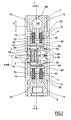
- the press comprises eight crimping inserts 2 which are radially disposed, angularly equidistant, about a common central axis (A), and are each formed from a metal block presenting, facing said central axis A, an active part 20 shaped as a circular sector tapered towards its end.
- the active parts 20 of all the crimping inserts 2 define a perfectly circular annular seat 3 for axially housing a connection sleeve positioned at the ends of two pipes to be connected together.
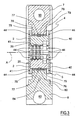
- each active part 20 comprises three separate teeth aligned along a direction parallel to the central axis A (see Figures 2 and 3 ), they being intended to be pressed radially against said connection sleeve, such as to deform it and fix it securely to the pipes.
- the crimping inserts 2 are carried by an insert carrier frame formed from two separate identical half-frames, an upper 4 and lower .5 respectively, symmetrically opposing about an ideal plane of symmetry B passing through the central axis A.
- Said half-frames 4 and 5 carry respectively one half of the crimping inserts 2, and close onto two cylindrical spacers 6 individually locked between two receiving cradles 6' and 6" which face each other and are provided in one and the other half-frame 4 and 5 respectively (see Figures 1 , 4 and 5 ).
- Each half-frame 4 and 5 consists of two specularly disposed identical profiled plates, namely a rear 40 and a front 41, which are perpendicular to the central axis A and are connected together by two hexagonal side spacers 42 and a rectangular central spacer 43 (also see Figures 2 and 3 ).
- the facing sides of said rear plate 40 and front plate 41 are each grooved by four full-length prismatic channels 44 (see Figure 1 ) which, arranged as a fan, extend longitudinally, each along its own radial direction from the central axis A.
- a crimping insert 2 which is orientated with its active part 20 facing the central axis A and is free to slide in a radial direction guided by the channels 44.
- each guide channel 44 is substantially less than the width of the crimping inserts 2, and equal to about 8% of this width, to achieve a limited friction surface which facilitates sliding and reduces wear.
- the two rear plates 40 and the two front plates 41 are formed from a monolithic flange having a profile symmetrical about the said plane of symmetry B, and which is firstly machined to form the guide channels 44 and then divided, along said plane B, into two identical half-flanges to form said rear plates 40 or front plates 41 (see Figures 4 and 5 as reference).
- two lateral holes are initially provided in the flange with their centre slightly below the plane of symmetry B and their diameter equal to the diameter of the spacer cylinders 6.
- the upper half-frame 4 and lower half-frame 5 are supported respectively by an upper crosspiece 7 and lower crosspiece 8, which are mutually movable along a direction C, perpendicular to the ideal plane of symmetry B.
- Said crosspieces 7 and 8 are each provided with a central rib, 70 and 80 respectively, of thickness substantially equal to the distance which separates the rear plates 40 from the front plates 41, and partially interposed between these latter.
- the central rib 70 comprises a recess of lunette shape symmetrically faced by another lunette provided in the opposing central rib 80 (see Figure 1 ).
- Each lunette presents a substantially V-shaped profile, with two mutually perpendicular oblique walls, both inclined to the direction C in which the crosspieces 7 and 8 mutually move.
- Said oblique walls are both provided with a reinforcement plate 75, preferably of very hard metal, which provides a thrust surface 79 on which two respective crimping inserts 2 rest; said crimping inserts 2 have their rear cut to flute mouthpiece shape, to rest on said thrust surface 79 along an extended contact surface.
- a magnetic pad 76 is interposed between each reinforcement plate 75 and a respective crimping insert 2, to always maintain them in mutual contact, it being partially housed in a hole provided in the rear of the crimping insert 2, and projects therefrom to engage the interior of a rectilinear groove 77 provided in the reinforcement plate 75.
- the housing hole has a depth of about one third of the thickness of the magnetic pad 76, while the groove 77 has a depth of about three quarters of said thickness, in order to leave a suitable clearance.
- each magnetic pad 76 is rigidly fixed in a hole of the relative reinforcement plate 75 and projects therefrom to partially engage in a groove in the rear of the insert 2.
- each half-frame 4 and 5 is connected to the relative crosspiece 7 and 8 by two cylindrical pins 71 which project from both sides of the central rib 70 and 80 to engage in two corresponding slots 72 provided in the rear plate 40 and front plate 41, said slots 72 extending along the movement direction C of the crosspieces 7 and 8, to enable their relative movement.
- each half-frame 4 and 5 and the relative crosspiece 7 and 8 two springs 74 are interposed (see Figure 2 ), each of which is carried by a respective guide rod 45 fixed to the central spacer 43 of the half-frame 4 and 5, and is partially housed axially within a corresponding dead-ended hole 73 provided in the central ribs 70 and 80.
- the springs 74 perform the double function of constantly pressing the half-frames 4 and 5 against the spacer cylinders 6, to ensure correct positioning of the crimping inserts 2, and to oppose the mutual approach movement of the crosspieces 7 and 8.
- the lower crosspiece 8 slidably receives two shafts 81 projecting in the said movement direction C, these passing through two respective receiving holes 78 in the upper crosspiece 7, where they are removably locked by locking means described in detail hereinafter.
- Each projecting shaft 81 is provided with a wide disc 82 slidably inserted into a respective cylindrical chamber 83 of the lower crosspiece 8, closed lowerly by a metal plug 87 retained by a retaining ring 88.
- pressurized oil is fed into each cylindrical chamber 83 from a conduit 84 connected to an external source (not shown), via a manifold 85 provided in a sleeve 86 fixed to the lower crosspiece 8.
- Both the central ribs 70 and 80 move simultaneously between the rear plate 40 and the front plate 41 of the respective half-frame 4 and 5, to cause the thrust surfaces 79 to slide in contact with the rear of the corresponding crimping inserts 2, and hence cause these latter to slide simultaneously in a radial direction towards the central axis A, to deform the connection sleeve (see Figure 5 ).
- the magnetic pads 76 slide rigid with the respective crimping insert 2 within the groove 77 provided in the thrust surface 79.
- connection sleeve to be crimped within the annular seat 3 or, vice versa, to extract it after deformation, it merely has to be inserted axially into or withdrawn from the annular seat 3.
- the upper crosspiece 7 and lower crosspiece 8 have merely to be separated from each other, as shown in Figure 7 .
- an adjustment screw 89 is provided, associated with the metal closure plug 87 of one of said cylindrical chambers 83, and movable in the direction in which the wide disc 82 slides: by screwing down the screw 89 the stroke of the projecting shafts 81 is reduced and the crimping diameter increased, whereas by unscrewing it, said stroke is increased and the crimping diameter reduced.
- the said means for locking the upper crosspiece 7 to the projecting shafts 81 comprise a generally cylindrical latch 9 slidably inserted into a transverse hole 90 which is provided at the top of the upper crosspiece 7, and into which the receiving holes 78 open.
- the top of said latch 9 presents two separate recesses 91, provided lowerly with a respective aperture 92 passing through its thickness.
- the apertures 92 are shaped to both present a substantially circular wide portion 92' and a narrow portion 92" which extends as a slot in the direction in which the latch 9 slides, and in the same sense (see Figures 6a and 6b ).
- the latch 9 can slide within the transverse hole 90 between two separate positions, one being a release position in which the wide portions 92' of the apertures 92 are aligned with the holes 78 receiving the projecting shafts 81, and the other an engagement position in which they are offset.
- the projecting shafts 81 In proximity to their free end, the projecting shafts 81 present two parallel cuts defining an intermediate portion 93 of reduced cross-section to slidably engage with one of said narrow portions 92", they bounding a cylindrical end head 94.
- the projecting shafts 81 can be inserted into the holes 78 of the upper crosspiece 7 and through the wide portions 92' of the apertures 92, until their cylindrical heads 94 are positioned within the recess 91; then on moving the latch 9 into the engagement position (see Figure 6a ), the narrow portions 92" slide as an exact fit along the narrow cross-section portions 93 of the projecting shafts 81, to secure the upper crosspiece 7 to the lower crosspiece 8.
- a manual screw 10 is screwed into it, this being slidably received in a slot 95 provided in the top of the upper crosspiece 7; furthermore, to further ensure correct location of the of the latch 9 in the engagement position, it is provided with an elastic stop 11 which, when this position has been attained, snaps into said slot 95.
- the crimping inserts 2 can be advantageously replaced by simply pulling them towards the end of the respective guide channel 44 until the magnetic attraction of the magnetic pad 76 is overcome (see Figure 7 ), this remaining attached to the reinforcement plate 75 because of its greater metallic mass compared with the insert 2.
- the press can be adapted for other uses, without changing the configuration of the press 1: the press 1 can be provided with accessories which enable it to operate for example as a punch, as shown in Figure 8 .
- Said forks 12 are insertedly coupled to a punch 120 and die 121 respectively, which are made to mutually approach by the movement of the crosspieces 7 and 8 in the direction C.
Landscapes
- Engineering & Computer Science (AREA)
- Mechanical Engineering (AREA)
- Automatic Assembly (AREA)
- Joints Allowing Movement (AREA)
- Press Drives And Press Lines (AREA)
- Springs (AREA)
- Clamps And Clips (AREA)
- Mutual Connection Of Rods And Tubes (AREA)
Claims (17)
- Eine Universalpresse, ausgestattet mit zwei Querstücken (7, 8) gegeneinander beweglich in geradliniger Richtung (C) mit wechselseitiger Annäherungs- und Entfemungsbewegung, zur Wirkung auf eine Reihe von Quetscheinsätzen (2), so angeordnet, dass sie einen ringförmigen Aufnahmesitz (3) für eine Verbindungshülse bilden, um sie gleichzeitig zu dieser zu drängen und um sie gleichzeitig in die Gegenrichtung zurückzuziehen, unter Befolgung jeweils einer wechselseitigen Annäherungsbewegung und einer Entfernungsbewegung der besagten Querstücke (7, 8), wobei sie außerdem einen eingesetzten Tragerahmen (4, 5) aufweist, der zwischen den besagten Querstücken (7, 8) eingesetzt ist und eine Gruppe von Gleitsitzen (44) umfasst, die radial um eine zentrale Achse (A) angeordnet sind und die jeweils so angeordnet sind, dass sie einen entsprechenden Quetscheinsatz (2) aufnehmen und ihn mit einer Hin- und Herbewegung in radialer Richtung gegenüber der besagten zentralen Achse (A) verschieben, wobei die einzelnen Querstücke (7, 8) Schubflächen (79) aufweisen, die jeweils so angeordnet sind, dass sie durch Rückhaltevorrichtungen (76) ständig in Kontakt mit der Rückseite von zumindest einem Quetscheinsatz (2) bleiben, um den besagten Quetscheinsatz (2) in seine Bewegung in dem entsprechenden Gleitsitz (44) zu treiben, dadurch gekennzeichnet, dass die besagte Rückhaltevorrichtung für jeden Quetscheinsatz (2) einen Magnet (76) umfasst, der sich zwischen der Rückseite des Quetscheinsatzes (2) und der Schubfläche (79) befindet.
- Eine Presse gemäß Anspruch 1, dadurch gekennzeichnet, dass die besagten Schubflächen (79) in Richtung der entsprechenden Bewegung (C) der Querstücke (7, 8) geneigt sind.
- Eine Presse gemäß Anspruch 1, dadurch gekennzeichnet, dass die Rückseite der Quetscheinsätze so geformt ist, dass sie mit einer vergrößerten Kontaktfläche auf der entsprechenden Schubfläche (79) liegt.
- Eine Presse gemäß Anspruch 1, dadurch gekennzeichnet, dass die besagten Schubflächen (79) mit den Wänden von zwei einander symmetrisch gegenüberliegenden identischen Lünetten verbunden sind, die jeweils in dem einen und in dem anderen Querstück (7, 8) enthalten sind.
- Eine Presse gemäß Anspruch 4, dadurch gekennzeichnet, dass die besagten Lünetten ein im Wesentlichen V-förmiges Profil aufweisen, wobei die schrägen Wände jeweils die Schubfläche (79) tragen.
- Eine Presse gemäß Anspruch 5, dadurch gekennzeichnet, dass sich die besagten schrägen Wände rechtwinklig zueinander befinden.
- Eine Presse gemäß Anspruch 1, dadurch gekennzeichnet, dass die einzelnen Schubflächen (79) eine Verstärkungsplatte (75) aufweisen, die starr am entsprechenden Querstück (7, 8) befestigt ist.
- Eine Presse gemäß Anspruch 1, dadurch gekennzeichnet, dass der Halterungsrahmen aus zwei einander symmetrisch gegenüberliegenden identischen separaten Halbrahmen (4, 5) gebildet wird, die jeweils von einem entsprechenden Querstück (7, 8) getragen werden.
- Eine Presse gemäß Anspruch 8, dadurch gekennzeichnet, dass die einzelnen Halbrahmen (4, 5) von dem entsprechenden Querstück (7, 8) durch eine elastische Vorrichtung (74) gehalten werden, die sie ständig gegen die andere Rahmenhälfte drückt, während sich das Querstück (7, 8) relativ zu ihr bewegen kann.
- Eine Presse gemäß Anspruch 8, dadurch gekennzeichnet, dass die einzelnen Rahmenhälften (4, 5) zwei identische Außenplatten (40, 41) mit Abstand zueinander aufweisen, wobei die einzelnen Gleitsitze durch zwei einander gegenüberliegende Führungskanäle (44) gebildet werden, die die Außenseiten der Außenplatten (40, 41) jeweils aufweisen; die Querstücke (7, 8) weisen jeweils eine entsprechende zentrale Rippe (70, 80) auf, die zwischen den Außenplatten (40, 41) der entsprechenden Rahmenhälfte (4, 5) verschoben werden kann und die besagten Schubflächen (79) trägt.
- Eine Presse gemäß Anspruch 8, dadurch gekennzeichnet, dass sich zwischen den besagten Rahmenhälften (4, 5) zwei Abstandszylinder (6) befinden, die parallel zur zentralen Achse (A) angeordnet sind und einzeln zwischen zwei Halterungen (6', 6") in der einen und in der anderen Rahmenhälfte (4, 5) gehalten werden.
- Eine Presse gemäß Anspruch 1, dadurch gekennzeichnet, dass ein erstes Querstück (8) zwei überstehende Wellen (81) aufweist, die in zwei entsprechenden Aufnahmelöcher (78) im zweiten Querstück (7) eindringen und mit einer Sperrvorrichtung (9) in ihrem Inneren abnehmbar gesperrt werden können; die besagten überstehenden Wellen (81) gleiten gleichzeitig in der besagten Bewegungsrichtung (C), so dass sich die Querstücke (7, 8) aneinander annähern oder voneinander entfernen.
- Eine Presse gemäß Anspruch 12, dadurch gekennzeichnet, dass die besagte Sperrvorrichtung einen Riegel (9) aufweist, der verschiebbar in einer Queröffnung (90) im zweiten Querstück (7) enthalten ist und in dem sich die besagten Aufnahmelöcher (78) für die überstehenden Wellen (81) öffnen; der besagte Riegel (9) kann in eine Eingreifposition gebracht werden, in der er in beide überstehenden Wellen (81) passt, um sie an das besagte zweite Querstück (7) zu sperren, und in eine offene Position, in der er aus dem besagten Sitz austritt, so dass die überstehenden Wellen (81) in die Aufnahmelöcher (78) eingesetzt werden und sich aus ihnen entfernen können.
- Eine Presse gemäß Anspruch 13, dadurch gekennzeichnet, dass der besagte Riegel (9) zwei separate durchgehende Öffnungen (92) aufweist, die jeweils so geformt sind, dass sie Folgendes aufweisen:- einen breiten Teil (92'), der zu einem entsprechenden Aufnahmeloch (78) weist, wenn sich der Riegel (9) in der offenen Position befindet, damit die überstehenden Wellen (81) hindurchgehen können, und- einen schmalen Teil (92"), verlängert wie ein Schlitz in der Richtung, in der der Riegel (9) gleitet, um genau in einen Zwischenteil (93) mit reduziertem Querschnitt der besagten überstehenden Welle (81) einzugreifen, wenn die letztere in die Öffnung (92) eingesetzt ist und sich der Riegel (9) in seiner Eingreifposition befindet.
- Eine Presse gemäß Anspruch 13, dadurch gekennzeichnet, dass der besagte Riegel (9) eine im Allgemeinen zylindrische Form besitzt und zwei Aussparungen (91) aufweist, die an den besagten durchgehenden Öffnungen (92) auf der Gegenseite der Aufnahmelöcher (78) positioniert sind und die jeweils in der Lage sind, das Endteil (94) einer entsprechenden überstehenden Welle (81) aufzunehmen.
- Eine Presse gemäß Anspruch 13, dadurch gekennzeichnet, dass jede überstehende Welle (81) eine breite Scheibe (82) aufweist, die verschiebbar in einer entsprechenden zylindrischen Kammer (83) des ersten Querstücks (8) enthalten ist, wobei die Kammer mit unter Druck stehender Flüssigkeit gespeist wird, um die Scheibe (82) in die Richtung zu drängen, die bewirkt, dass sich die Querstücke (7, 8) einander annähern.
- Eine Presse gemäß Anspruch 16, dadurch gekennzeichnet, dass zumindest eine der besagten zylindrischen Kammern (83) mit einem Element (89) verschlossen ist, das in der Gleitrichtung der breiten Schreibe (82) beweglich ist und eine Änderung des Hub der letzteren gestattet.
Applications Claiming Priority (2)
| Application Number | Priority Date | Filing Date | Title |
|---|---|---|---|
| IT000091A ITRE20050091A1 (it) | 2005-07-26 | 2005-07-26 | Pressetta universale per la deformazione delle boccole di raccordo di tubi, e per altri usi |
| PCT/EP2006/006875 WO2007012411A1 (en) | 2005-07-26 | 2006-07-11 | Universal press for deforming pipe connection sleeves, and for other uses |
Publications (2)
| Publication Number | Publication Date |
|---|---|
| EP1907149A1 EP1907149A1 (de) | 2008-04-09 |
| EP1907149B1 true EP1907149B1 (de) | 2009-05-13 |
Family
ID=37074230
Family Applications (1)
| Application Number | Title | Priority Date | Filing Date |
|---|---|---|---|
| EP06762569A Not-in-force EP1907149B1 (de) | 2005-07-26 | 2006-07-11 | Universalpresse zur deformierung von rohrverbindungshülsen und für andere einsätze |
Country Status (6)
| Country | Link |
|---|---|
| US (1) | US20080209975A1 (de) |
| EP (1) | EP1907149B1 (de) |
| AT (1) | ATE431204T1 (de) |
| DE (1) | DE602006006834D1 (de) |
| IT (1) | ITRE20050091A1 (de) |
| WO (1) | WO2007012411A1 (de) |
Families Citing this family (3)
| Publication number | Priority date | Publication date | Assignee | Title |
|---|---|---|---|---|
| JP6505999B2 (ja) * | 2014-09-05 | 2019-04-24 | ファナック株式会社 | 弾性体を介して線条体を固定する線条体固定装置 |
| DE202022102074U1 (de) * | 2022-04-19 | 2022-04-27 | Uniflex - Hydraulik GmbH | Radialpresse |
| US12397337B2 (en) * | 2022-12-15 | 2025-08-26 | Winton Machine Company | Crimping device |
Family Cites Families (10)
| Publication number | Priority date | Publication date | Assignee | Title |
|---|---|---|---|---|
| US3731518A (en) * | 1971-05-26 | 1973-05-08 | G Blocher | Crimping die arrangement |
| US4785656A (en) * | 1986-10-01 | 1988-11-22 | Stratoflex, Inc. | Crimping machine for hose and fitting assemblies |
| DE3808344A1 (de) * | 1988-03-12 | 1989-09-28 | Horst Baltschun | Saeulenpresse fuer grosse aussermittige belastungen und schnittschlagdaempfung |
| US5092152A (en) * | 1990-09-28 | 1992-03-03 | Parker-Hannifin Corporation | Crimping machine |
| DE4135465A1 (de) * | 1991-10-28 | 1993-04-29 | Schroeck Peter Dipl Ing Fh | Radialpresse mit zwei radial gegeneinander beweglichen pressenjochen |
| US5257525A (en) * | 1992-06-24 | 1993-11-02 | Atco Products, Inc. | Portable slim-line hose fitting crimper |
| JPH11508825A (ja) * | 1996-03-08 | 1999-08-03 | エアロクイップ コーポレイション | クリンパ組立体 |
| DE19814474C1 (de) * | 1998-04-01 | 1999-07-08 | Peter Dipl Ing Schroeck | Radialpreßwerkzeug für die Verformung rotationssymmetrischer Werkstücke |
| US6257042B1 (en) * | 1999-11-05 | 2001-07-10 | Lillbacka Oy | Open throat crimping machine |
| DE19958103C1 (de) * | 1999-12-02 | 2001-03-01 | Peter Schroeck | Preßwerkzeug zum Verpressen von rotationssymmetrischen Hohlkörpern |
-
2005
- 2005-07-26 IT IT000091A patent/ITRE20050091A1/it unknown
-
2006
- 2006-07-11 AT AT06762569T patent/ATE431204T1/de not_active IP Right Cessation
- 2006-07-11 DE DE602006006834T patent/DE602006006834D1/de active Active
- 2006-07-11 EP EP06762569A patent/EP1907149B1/de not_active Not-in-force
- 2006-07-11 US US11/996,988 patent/US20080209975A1/en not_active Abandoned
- 2006-07-11 WO PCT/EP2006/006875 patent/WO2007012411A1/en not_active Ceased
Also Published As
| Publication number | Publication date |
|---|---|
| ATE431204T1 (de) | 2009-05-15 |
| ITRE20050091A1 (it) | 2007-01-27 |
| WO2007012411A1 (en) | 2007-02-01 |
| US20080209975A1 (en) | 2008-09-04 |
| DE602006006834D1 (de) | 2009-06-25 |
| EP1907149A1 (de) | 2008-04-09 |
Similar Documents
| Publication | Publication Date | Title |
|---|---|---|
| EP3256272B1 (de) | Stanzanordnung mit austauschbarer, durch einen kopplungsstift gesicherte stanzspitze | |
| US6799758B2 (en) | Clamping apparatus with a clamping chuck and a work piece carrier releasably connectable thereto | |
| KR100307922B1 (ko) | 상부공구 홀딩장치 및 그 장치로부터 상부공구를 분리하는 방법 | |
| US20090007738A1 (en) | Method and tool for producing a press joint connection | |
| US20170320120A1 (en) | Punch and die holding apparatus and method | |
| CN101146628B (zh) | 用于压弯机的推板工具夹持器 | |
| KR102625563B1 (ko) | 공작 기계 상에 피가공물을 고정하는 장치 | |
| US5720197A (en) | Crimper assembly | |
| EP1250968A1 (de) | Pressvorrichtung | |
| EP1907149B1 (de) | Universalpresse zur deformierung von rohrverbindungshülsen und für andere einsätze | |
| US8281636B2 (en) | Heading device | |
| JP2020006394A (ja) | 金型ホルダ | |
| EP3311931B1 (de) | Verriegelungsvorrichtung für die werkzeuge einer bearbeitungsmaschine, insbesondere für eine biegepresse | |
| CA3088182A1 (en) | Stamping dies and guided retainer devices for use in same | |
| JP7583748B2 (ja) | ツールホルダ用のクランピングデバイス | |
| CA2642470A1 (en) | Crimping apparatus with a support structure including first and second portions | |
| EP0885075A1 (de) | Krimpwekzeug | |
| KR20150041986A (ko) | 브이홈 가공기의 바이트 | |
| EP1165264B1 (de) | Werkzeughaltevorrichtung für abkantbiegepressen | |
| EP3708351B1 (de) | Pressmaschine | |
| CN114798871A (zh) | 一种便于对冲压头和冲压座进行更换的冲压设备 | |
| CN221388968U (zh) | 一种车床夹头 | |
| US20250041925A1 (en) | Radial press | |
| CA2582146A1 (en) | Device for fastening a covering on a cylinder of a rotary press | |
| US20070186615A1 (en) | Crimping apparatus and methods of crimping with retainers |
Legal Events
| Date | Code | Title | Description |
|---|---|---|---|
| PUAI | Public reference made under article 153(3) epc to a published international application that has entered the european phase |
Free format text: ORIGINAL CODE: 0009012 |
|
| 17P | Request for examination filed |
Effective date: 20080128 |
|
| AK | Designated contracting states |
Kind code of ref document: A1 Designated state(s): AT BE BG CH CY CZ DE DK EE ES FI FR GB GR HU IE IS IT LI LT LU LV MC NL PL PT RO SE SI SK TR |
|
| 17Q | First examination report despatched |
Effective date: 20080620 |
|
| GRAP | Despatch of communication of intention to grant a patent |
Free format text: ORIGINAL CODE: EPIDOSNIGR1 |
|
| GRAS | Grant fee paid |
Free format text: ORIGINAL CODE: EPIDOSNIGR3 |
|
| GRAA | (expected) grant |
Free format text: ORIGINAL CODE: 0009210 |
|
| AK | Designated contracting states |
Kind code of ref document: B1 Designated state(s): AT BE BG CH CY CZ DE DK EE ES FI FR GB GR HU IE IS IT LI LT LU LV MC NL PL PT RO SE SI SK TR |
|
| REG | Reference to a national code |
Ref country code: GB Ref legal event code: FG4D |
|
| REG | Reference to a national code |
Ref country code: CH Ref legal event code: EP |
|
| REG | Reference to a national code |
Ref country code: IE Ref legal event code: FG4D |
|
| REF | Corresponds to: |
Ref document number: 602006006834 Country of ref document: DE Date of ref document: 20090625 Kind code of ref document: P |
|
| PGFP | Annual fee paid to national office [announced via postgrant information from national office to epo] |
Ref country code: ES Payment date: 20090522 Year of fee payment: 4 |
|
| PG25 | Lapsed in a contracting state [announced via postgrant information from national office to epo] |
Ref country code: ES Free format text: LAPSE BECAUSE OF FAILURE TO SUBMIT A TRANSLATION OF THE DESCRIPTION OR TO PAY THE FEE WITHIN THE PRESCRIBED TIME-LIMIT Effective date: 20090824 Ref country code: FI Free format text: LAPSE BECAUSE OF FAILURE TO SUBMIT A TRANSLATION OF THE DESCRIPTION OR TO PAY THE FEE WITHIN THE PRESCRIBED TIME-LIMIT Effective date: 20090513 Ref country code: PT Free format text: LAPSE BECAUSE OF FAILURE TO SUBMIT A TRANSLATION OF THE DESCRIPTION OR TO PAY THE FEE WITHIN THE PRESCRIBED TIME-LIMIT Effective date: 20090913 Ref country code: LT Free format text: LAPSE BECAUSE OF FAILURE TO SUBMIT A TRANSLATION OF THE DESCRIPTION OR TO PAY THE FEE WITHIN THE PRESCRIBED TIME-LIMIT Effective date: 20090513 Ref country code: AT Free format text: LAPSE BECAUSE OF FAILURE TO SUBMIT A TRANSLATION OF THE DESCRIPTION OR TO PAY THE FEE WITHIN THE PRESCRIBED TIME-LIMIT Effective date: 20090513 |
|
| NLV1 | Nl: lapsed or annulled due to failure to fulfill the requirements of art. 29p and 29m of the patents act | ||
| PG25 | Lapsed in a contracting state [announced via postgrant information from national office to epo] |
Ref country code: SI Free format text: LAPSE BECAUSE OF FAILURE TO SUBMIT A TRANSLATION OF THE DESCRIPTION OR TO PAY THE FEE WITHIN THE PRESCRIBED TIME-LIMIT Effective date: 20090513 Ref country code: SE Free format text: LAPSE BECAUSE OF FAILURE TO SUBMIT A TRANSLATION OF THE DESCRIPTION OR TO PAY THE FEE WITHIN THE PRESCRIBED TIME-LIMIT Effective date: 20090813 Ref country code: PL Free format text: LAPSE BECAUSE OF FAILURE TO SUBMIT A TRANSLATION OF THE DESCRIPTION OR TO PAY THE FEE WITHIN THE PRESCRIBED TIME-LIMIT Effective date: 20090513 Ref country code: NL Free format text: LAPSE BECAUSE OF FAILURE TO SUBMIT A TRANSLATION OF THE DESCRIPTION OR TO PAY THE FEE WITHIN THE PRESCRIBED TIME-LIMIT Effective date: 20090513 Ref country code: LV Free format text: LAPSE BECAUSE OF FAILURE TO SUBMIT A TRANSLATION OF THE DESCRIPTION OR TO PAY THE FEE WITHIN THE PRESCRIBED TIME-LIMIT Effective date: 20090513 Ref country code: IS Free format text: LAPSE BECAUSE OF FAILURE TO SUBMIT A TRANSLATION OF THE DESCRIPTION OR TO PAY THE FEE WITHIN THE PRESCRIBED TIME-LIMIT Effective date: 20090913 |
|
| PG25 | Lapsed in a contracting state [announced via postgrant information from national office to epo] |
Ref country code: CZ Free format text: LAPSE BECAUSE OF FAILURE TO SUBMIT A TRANSLATION OF THE DESCRIPTION OR TO PAY THE FEE WITHIN THE PRESCRIBED TIME-LIMIT Effective date: 20090513 Ref country code: DK Free format text: LAPSE BECAUSE OF FAILURE TO SUBMIT A TRANSLATION OF THE DESCRIPTION OR TO PAY THE FEE WITHIN THE PRESCRIBED TIME-LIMIT Effective date: 20090513 Ref country code: EE Free format text: LAPSE BECAUSE OF FAILURE TO SUBMIT A TRANSLATION OF THE DESCRIPTION OR TO PAY THE FEE WITHIN THE PRESCRIBED TIME-LIMIT Effective date: 20090513 |
|
| PG25 | Lapsed in a contracting state [announced via postgrant information from national office to epo] |
Ref country code: SK Free format text: LAPSE BECAUSE OF FAILURE TO SUBMIT A TRANSLATION OF THE DESCRIPTION OR TO PAY THE FEE WITHIN THE PRESCRIBED TIME-LIMIT Effective date: 20090513 Ref country code: MC Free format text: LAPSE BECAUSE OF NON-PAYMENT OF DUE FEES Effective date: 20090731 Ref country code: BE Free format text: LAPSE BECAUSE OF FAILURE TO SUBMIT A TRANSLATION OF THE DESCRIPTION OR TO PAY THE FEE WITHIN THE PRESCRIBED TIME-LIMIT Effective date: 20090513 |
|
| PLBE | No opposition filed within time limit |
Free format text: ORIGINAL CODE: 0009261 |
|
| STAA | Information on the status of an ep patent application or granted ep patent |
Free format text: STATUS: NO OPPOSITION FILED WITHIN TIME LIMIT |
|
| PG25 | Lapsed in a contracting state [announced via postgrant information from national office to epo] |
Ref country code: BG Free format text: LAPSE BECAUSE OF FAILURE TO SUBMIT A TRANSLATION OF THE DESCRIPTION OR TO PAY THE FEE WITHIN THE PRESCRIBED TIME-LIMIT Effective date: 20090813 |
|
| 26N | No opposition filed |
Effective date: 20100216 |
|
| PG25 | Lapsed in a contracting state [announced via postgrant information from national office to epo] |
Ref country code: IE Free format text: LAPSE BECAUSE OF NON-PAYMENT OF DUE FEES Effective date: 20090711 |
|
| PG25 | Lapsed in a contracting state [announced via postgrant information from national office to epo] |
Ref country code: GR Free format text: LAPSE BECAUSE OF FAILURE TO SUBMIT A TRANSLATION OF THE DESCRIPTION OR TO PAY THE FEE WITHIN THE PRESCRIBED TIME-LIMIT Effective date: 20090814 |
|
| PGFP | Annual fee paid to national office [announced via postgrant information from national office to epo] |
Ref country code: DE Payment date: 20100729 Year of fee payment: 5 Ref country code: FR Payment date: 20100730 Year of fee payment: 5 |
|
| PG25 | Lapsed in a contracting state [announced via postgrant information from national office to epo] |
Ref country code: RO Free format text: LAPSE BECAUSE OF FAILURE TO SUBMIT A TRANSLATION OF THE DESCRIPTION OR TO PAY THE FEE WITHIN THE PRESCRIBED TIME-LIMIT Effective date: 20090513 |
|
| REG | Reference to a national code |
Ref country code: CH Ref legal event code: PL |
|
| GBPC | Gb: european patent ceased through non-payment of renewal fee |
Effective date: 20100711 |
|
| PG25 | Lapsed in a contracting state [announced via postgrant information from national office to epo] |
Ref country code: IT Free format text: LAPSE BECAUSE OF FAILURE TO SUBMIT A TRANSLATION OF THE DESCRIPTION OR TO PAY THE FEE WITHIN THE PRESCRIBED TIME-LIMIT Effective date: 20090513 |
|
| PG25 | Lapsed in a contracting state [announced via postgrant information from national office to epo] |
Ref country code: LU Free format text: LAPSE BECAUSE OF NON-PAYMENT OF DUE FEES Effective date: 20090711 Ref country code: CH Free format text: LAPSE BECAUSE OF NON-PAYMENT OF DUE FEES Effective date: 20100731 Ref country code: LI Free format text: LAPSE BECAUSE OF NON-PAYMENT OF DUE FEES Effective date: 20100731 |
|
| PG25 | Lapsed in a contracting state [announced via postgrant information from national office to epo] |
Ref country code: HU Free format text: LAPSE BECAUSE OF FAILURE TO SUBMIT A TRANSLATION OF THE DESCRIPTION OR TO PAY THE FEE WITHIN THE PRESCRIBED TIME-LIMIT Effective date: 20091114 |
|
| PG25 | Lapsed in a contracting state [announced via postgrant information from national office to epo] |
Ref country code: GB Free format text: LAPSE BECAUSE OF NON-PAYMENT OF DUE FEES Effective date: 20100711 |
|
| PG25 | Lapsed in a contracting state [announced via postgrant information from national office to epo] |
Ref country code: TR Free format text: LAPSE BECAUSE OF FAILURE TO SUBMIT A TRANSLATION OF THE DESCRIPTION OR TO PAY THE FEE WITHIN THE PRESCRIBED TIME-LIMIT Effective date: 20090513 |
|
| PG25 | Lapsed in a contracting state [announced via postgrant information from national office to epo] |
Ref country code: CY Free format text: LAPSE BECAUSE OF FAILURE TO SUBMIT A TRANSLATION OF THE DESCRIPTION OR TO PAY THE FEE WITHIN THE PRESCRIBED TIME-LIMIT Effective date: 20090513 |
|
| REG | Reference to a national code |
Ref country code: FR Ref legal event code: ST Effective date: 20120330 |
|
| PG25 | Lapsed in a contracting state [announced via postgrant information from national office to epo] |
Ref country code: FR Free format text: LAPSE BECAUSE OF NON-PAYMENT OF DUE FEES Effective date: 20110801 Ref country code: DE Free format text: LAPSE BECAUSE OF NON-PAYMENT OF DUE FEES Effective date: 20120201 |
|
| REG | Reference to a national code |
Ref country code: DE Ref legal event code: R119 Ref document number: 602006006834 Country of ref document: DE Effective date: 20120201 |