EP1907171B1 - Rail de guidage lineaire pour un systeme de guidage lineaire pourvu d'une rainure a fluide de refroidissement - Google Patents
Rail de guidage lineaire pour un systeme de guidage lineaire pourvu d'une rainure a fluide de refroidissement Download PDFInfo
- Publication number
- EP1907171B1 EP1907171B1 EP06742848A EP06742848A EP1907171B1 EP 1907171 B1 EP1907171 B1 EP 1907171B1 EP 06742848 A EP06742848 A EP 06742848A EP 06742848 A EP06742848 A EP 06742848A EP 1907171 B1 EP1907171 B1 EP 1907171B1
- Authority
- EP
- European Patent Office
- Prior art keywords
- linear guide
- guide rail
- coolant
- groove
- coolant groove
- Prior art date
- Legal status (The legal status is an assumption and is not a legal conclusion. Google has not performed a legal analysis and makes no representation as to the accuracy of the status listed.)
- Expired - Lifetime
Links
Images


Classifications
-
- F—MECHANICAL ENGINEERING; LIGHTING; HEATING; WEAPONS; BLASTING
- F16—ENGINEERING ELEMENTS AND UNITS; GENERAL MEASURES FOR PRODUCING AND MAINTAINING EFFECTIVE FUNCTIONING OF MACHINES OR INSTALLATIONS; THERMAL INSULATION IN GENERAL
- F16C—SHAFTS; FLEXIBLE SHAFTS; ELEMENTS OR CRANKSHAFT MECHANISMS; ROTARY BODIES OTHER THAN GEARING ELEMENTS; BEARINGS
- F16C29/00—Bearings for parts moving only linearly
- F16C29/005—Guide rails or tracks for a linear bearing, i.e. adapted for movement of a carriage or bearing body there along
-
- B—PERFORMING OPERATIONS; TRANSPORTING
- B23—MACHINE TOOLS; METAL-WORKING NOT OTHERWISE PROVIDED FOR
- B23Q—DETAILS, COMPONENTS, OR ACCESSORIES FOR MACHINE TOOLS, e.g. ARRANGEMENTS FOR COPYING OR CONTROLLING; MACHINE TOOLS IN GENERAL CHARACTERISED BY THE CONSTRUCTION OF PARTICULAR DETAILS OR COMPONENTS; COMBINATIONS OR ASSOCIATIONS OF METAL-WORKING MACHINES, NOT DIRECTED TO A PARTICULAR RESULT
- B23Q1/00—Members which are comprised in the general build-up of a form of machine, particularly relatively large fixed members
- B23Q1/01—Frames, beds, pillars or like members; Arrangement of ways
- B23Q1/017—Arrangements of ways
-
- B—PERFORMING OPERATIONS; TRANSPORTING
- B23—MACHINE TOOLS; METAL-WORKING NOT OTHERWISE PROVIDED FOR
- B23Q—DETAILS, COMPONENTS, OR ACCESSORIES FOR MACHINE TOOLS, e.g. ARRANGEMENTS FOR COPYING OR CONTROLLING; MACHINE TOOLS IN GENERAL CHARACTERISED BY THE CONSTRUCTION OF PARTICULAR DETAILS OR COMPONENTS; COMBINATIONS OR ASSOCIATIONS OF METAL-WORKING MACHINES, NOT DIRECTED TO A PARTICULAR RESULT
- B23Q11/00—Accessories fitted to machine tools for keeping tools or parts of the machine in good working condition or for cooling work; Safety devices specially combined with or arranged in, or specially adapted for use in connection with, machine tools
- B23Q11/12—Arrangements for cooling or lubricating parts of the machine
- B23Q11/126—Arrangements for cooling or lubricating parts of the machine for cooling only
-
- F—MECHANICAL ENGINEERING; LIGHTING; HEATING; WEAPONS; BLASTING
- F16—ENGINEERING ELEMENTS AND UNITS; GENERAL MEASURES FOR PRODUCING AND MAINTAINING EFFECTIVE FUNCTIONING OF MACHINES OR INSTALLATIONS; THERMAL INSULATION IN GENERAL
- F16C—SHAFTS; FLEXIBLE SHAFTS; ELEMENTS OR CRANKSHAFT MECHANISMS; ROTARY BODIES OTHER THAN GEARING ELEMENTS; BEARINGS
- F16C29/00—Bearings for parts moving only linearly
- F16C29/08—Arrangements for covering or protecting the ways
- F16C29/082—Arrangements for covering or protecting the ways fixed to the way
-
- F—MECHANICAL ENGINEERING; LIGHTING; HEATING; WEAPONS; BLASTING
- F16—ENGINEERING ELEMENTS AND UNITS; GENERAL MEASURES FOR PRODUCING AND MAINTAINING EFFECTIVE FUNCTIONING OF MACHINES OR INSTALLATIONS; THERMAL INSULATION IN GENERAL
- F16C—SHAFTS; FLEXIBLE SHAFTS; ELEMENTS OR CRANKSHAFT MECHANISMS; ROTARY BODIES OTHER THAN GEARING ELEMENTS; BEARINGS
- F16C37/00—Cooling of bearings
-
- F—MECHANICAL ENGINEERING; LIGHTING; HEATING; WEAPONS; BLASTING
- F16—ENGINEERING ELEMENTS AND UNITS; GENERAL MEASURES FOR PRODUCING AND MAINTAINING EFFECTIVE FUNCTIONING OF MACHINES OR INSTALLATIONS; THERMAL INSULATION IN GENERAL
- F16C—SHAFTS; FLEXIBLE SHAFTS; ELEMENTS OR CRANKSHAFT MECHANISMS; ROTARY BODIES OTHER THAN GEARING ELEMENTS; BEARINGS
- F16C2322/00—Apparatus used in shaping articles
- F16C2322/39—General buildup of machine tools, e.g. spindles, slides, actuators
-
- F—MECHANICAL ENGINEERING; LIGHTING; HEATING; WEAPONS; BLASTING
- F16—ENGINEERING ELEMENTS AND UNITS; GENERAL MEASURES FOR PRODUCING AND MAINTAINING EFFECTIVE FUNCTIONING OF MACHINES OR INSTALLATIONS; THERMAL INSULATION IN GENERAL
- F16C—SHAFTS; FLEXIBLE SHAFTS; ELEMENTS OR CRANKSHAFT MECHANISMS; ROTARY BODIES OTHER THAN GEARING ELEMENTS; BEARINGS
- F16C29/00—Bearings for parts moving only linearly
- F16C29/04—Ball or roller bearings
- F16C29/06—Ball or roller bearings in which the rolling bodies circulate partly without carrying load
- F16C29/0633—Ball or roller bearings in which the rolling bodies circulate partly without carrying load with a bearing body defining a U-shaped carriage, i.e. surrounding a guide rail or track on three sides
-
- Y—GENERAL TAGGING OF NEW TECHNOLOGICAL DEVELOPMENTS; GENERAL TAGGING OF CROSS-SECTIONAL TECHNOLOGIES SPANNING OVER SEVERAL SECTIONS OF THE IPC; TECHNICAL SUBJECTS COVERED BY FORMER USPC CROSS-REFERENCE ART COLLECTIONS [XRACs] AND DIGESTS
- Y10—TECHNICAL SUBJECTS COVERED BY FORMER USPC
- Y10S—TECHNICAL SUBJECTS COVERED BY FORMER USPC CROSS-REFERENCE ART COLLECTIONS [XRACs] AND DIGESTS
- Y10S384/00—Bearings
- Y10S384/90—Cooling or heating
Definitions
- the invention relates to a linear guide rail and a linear guide system according to the preamble of claim 1 and 3, respectively.
- the invention relates to a linear guide rail with a movable by means of rolling elements along the linear guide rail guide carriage, the linear guide rail is provided at its top with Befest Trentsaus strictly adopted to this by means of screws or the like with a component or assembly of a machine tool or a machining center or the like connect to.
- the mounting recesses are covered by a cover band to provide a smooth surface and to prevent the ingress of chips, dirt or coolant into the space between the linear guide rail and the carriage.
- roller rail guides In machine tools, guide systems with rollers are frequently used or balls, so-called roller rail guides or ball rail guides used.
- the guides consist of guide rails and carriages.
- the carriages can be moved back and forth on the guide rails with relatively little force and at the same time with high rigidity.
- the guide rails are fastened to one component, the guide carriages are fastened to another component, eg a slide of the machine.
- a suitable drive for example ball screw drives or linear motors, generates a relative movement in the direction of the guide rails between the components. In this way, for example, delivery axes are built in machine tools.
- the axes are often moved at high speeds. Since the carriages are not frictionless due to their prestressing and possibly existing sealing elements, heat is generated on the guide rails in the process of the carriages. The heat heats not only the guide rails and carriages but also heat conduction and radiation and the components attached thereto. These expand in accordance with their thermal expansion coefficients. As a result, the machine deforms. There are additional inaccuracies and deviations in the processing, which are undesirable.
- the U.S.-A-5,431,497 describes a linear guide system with a linear guide rail, which is provided in its central region over its entire length with a bore through which a coolant is passed.
- a bore is on the one hand only with great effort and relatively short linear guide rails produced, on the other hand affects the hole attachment of the linear guide rail by means of central mounting screws.
- a cooling system for a machine tool in particular a grinding machine, previously known, which is designed as an open system and provides a spray head for supplying the cooling fluid and open gutters.
- a targeted control of the flow with cooling fluid is not possible.
- the invention has for its object to provide a linear guide system and an associated linear guide rail, which allow temperature control while avoiding the disadvantages known from the prior art.
- At least one coolant groove extending over part of the length of the linear guide rail is formed in the region of the linear guide rail.
- a coolant can thus be passed through in such a way that it optimally cools the linear guide rail.
- the coolant groove may be formed on the top or the bottom of the linear guide rail, it is also possible to form the coolant groove in a component, for example a machine bed and thus to use a known from the prior art linear guide rail. In all these cases, optimal cooling is ensured, which avoids changes in length due to heating.
- the invention is characterized by a number of significant advantages.
- the invention thus provides a very simple solution for tempering the guide rails, in which the heating is minimized.
- the guide rails are formed so that they have an angular, round or otherwise shaped coolant groove in the longitudinal direction at the top.
- the coolant groove thus connects the mounting recesses or depressions for the screws for fastening the guide rails.
- a closed cavity is created along the guide rail when the screw heads are sufficiently deep to secure the rail.
- the groove-shaped cross section alternates with the mounting recesses or depressions and the screws therein. This cavity is used according to the invention, in order to pass a suitable cooling liquid, for example water, and thus to temper the guide rail and to dissipate any resulting heat from the movement of the guide carriage.
- the coolant groove may be provided on the underside of the linear guide rail.
- This embodiment is particularly suitable for linear guide rails, in which no upper cover strip provided is and, for example, the screw holes are closed by plugs or the like.
- coolant groove directly in the component on which the linear guide rail is mounted.
- bulges or recesses in the region of the fastening screws may be possible in order to optimize their flow around.
- a suitable hose or pipe connection e.g. by a screw in the cover plate at the beginning and at the end of the guide rail advantageous.
- the cross-section of the cavity may be relatively small, since the heat generated by the process of the axes is also relatively low.
- the flow can be continuous or clocked or otherwise controlled according to the requirements of the processing.
- a great advantage of the invention is that the heat is dissipated directly at the point of origin.
- possible holes for coolant in the attached to the guides or carriages components could dissipate the heat only by heat conduction and are therefore less efficient.
- the inventive linear guide rail 1 according to the first embodiment is provided with mounting recesses 3 in order to fasten them by means of screws 7 to a component 8.
- the mounting recesses are stepped so that the head of the screw can be accommodated sunk accordingly.
- the number of screws and their size is also dependent on the structural conditions, as the design and dimensioning of the linear guide rail itself.
- the linear guide rail 1 is provided with a cover strip 4, which creates a flat surface and the mounting recesses 3 covers, so that no dirt, chips or the like in the space between the linear guide rail and on this linearly movable guide carriage 2 (see Fig. 3 ) can penetrate.
- a cover strip 4 which creates a flat surface and the mounting recesses 3 covers, so that no dirt, chips or the like in the space between the linear guide rail and on this linearly movable guide carriage 2 (see Fig. 3 ) can penetrate.
- Fig. 3 was omitted to represent the rolling elements (balls, rollers or the like), since these are known from the prior art. The same applies to further structural configurations of both the carriage and the linear guide rail.
- a coolant groove 5 is provided which extends over the length thereof and thereby connects the fastening recesses 3. Coolant can be supplied or removed by means of coolant connections 6, which can be mounted either at the top or at the front side of the linear guide rail Fig. 1 In the embodiment shown, for example, the right-hand screw 7 is sunk deeper in order to gain space for the connection of the coolant connection 6.
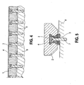
- Fig. 4 to 7 is the coolant groove 5 in the lower region of the linear guide rail 1, that is, formed on its underside.
- the dimensioning and width of the coolant groove 5 is adaptable to the requirements.
- the cross section can be increased, for example in the area of the screws 7, as the Fig. 5 shows.
- the remaining cross section may be semicircular or rectangular.
- Fig. 7a shows a perspective view of the linear guide rail 1 in a top view, while Fig. 7b a bottom view of this linear guide rail shows.
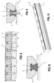
- the 8 to 11 show a further embodiment in an analogous representation of Fig. 4 to 7 ,
- the coolant groove 5 is formed in the component 8, on which the linear guide rail 1 is screwed or to which it is attached.
- the linear guide rail 1 does not need to be changed significantly compared to the prior art.
- the coolant groove 5 should have a larger cross-section in order to optimize the flow around.
- the invention is not limited to the embodiments shown, but it is in the context of the invention in particular possible to combine several of the above variants and thus, for example, on a linear guide rail 1 provide several coolant grooves.
Landscapes
- Engineering & Computer Science (AREA)
- General Engineering & Computer Science (AREA)
- Mechanical Engineering (AREA)
- Bearings For Parts Moving Linearly (AREA)
- Machine Tool Units (AREA)
- Mounting Of Bearings Or Others (AREA)
Claims (11)
- Rail de guidage linéaire pour un système de guidage linéaire avec au moins un chariot de guidage (2) mobile le long du rail de guidage linéaire (1) par l'intermédiaire d'éléments roulants, caractérisé en ce qu'au niveau du rail de guidage linéaire (1) est formée une rainure (5) pour fluide de refroidissement s'étendant sur au moins une partie de la longueur du rail de guidage linéaire (1), des raccords (6) pour fluide de refroidissement étant prévus pour introduire et évacuer du fluide de refroidissement dans et depuis la rainure (5) pour fluide de refroidissement, le rail de guidage linéaire (1) étant muni sur sa face supérieure d'évidements de fixation (3) qui sont recouverts par une bande de recouvrement (4) et sont munis de la rainure (5) pour fluide de refroidissement dans leur partie supérieure, de manière recouverte par la bande de couverture (4).
- Rail de guidage linéaire selon la revendication 1, caractérisé en ce que la rainure (5) pour fluide de refroidissement traverse les évidements de fixation (3).
- Système de guidage linéaire avec au moins un chariot de guidage (2) mobile le long d'un rail de guidage linéaire (1) par l'intermédiaire d'éléments roulants, le rail de guidage linéaire (1) étant fixé à un composant (8), caractérisé en ce qu'au niveau du rail de guidage linéaire (1) est formée une rainure (5) pour fluide de refroidissement s'étendant sur au moins une partie de la longueur du rail de guidage linéaire (1), des raccords (6) pour fluide de refroidissement étant prévus pour introduire et évacuer du fluide de refroidissement dans et depuis la rainure (5) pour fluide de refroidissement, la rainure (5) pour fluide de refroidissement étant recouverte à l'état monté du rail de guidage linéaire (1) sur le composant (8).
- Système de guidage linéaire selon la revendication 3, caractérisé en ce que la rainure (5) pour fluide de refroidissement est formée dans la surface d'un composant (8) d'une machine-outil.
- Système de guidage linéaire selon la revendication 3, caractérisé en ce que la rainure (5) pour fluide de refroidissement est réalisée dans la face inférieure du rail de guidage linéaire (1).
- Système de guidage linéaire selon l'une des revendications 1 à 5, caractérisé en ce que la rainure (5) pour fluide de refroidissement s'étend sur toute la longueur du rail de guidage linéaire (1).
- Système de guidage linéaire selon l'une des revendications 1 à 6, caractérisé en ce que la rainure (5) pour fluide de refroidissement est conformée pour acheminer du fluide de refroidissement sous pression négative.
- Système de guidage linéaire selon l'une des revendications 1 à 6, caractérisé en ce que la rainure (5) pour fluide de refroidissement est conformée pour acheminer du fluide de refroidissement sous pression positive.
- Système de guidage linéaire avec au moins un chariot de guidage (2) mobile le long d'un rail de guidage linéaire par l'intermédiaire d'éléments roulants, avec au moins un rail de guidage linéaire (1) selon l'une des revendications 1 ou 2.
- Procédé de fonctionnement d'un système de guidage linéaire selon la revendication 9 ou l'une des revendications 3 à 8, dans lequel un fluide de refroidissement est envoyé de manière continue à travers la rainure (5) pour fluide de refroidissement.
- Procédé de fonctionnement d'un système de guidage linéaire selon la revendication 9 ou l'une des revendications 3 à 8, dans lequel un fluide de refroidissement est envoyé de manière discontinue à travers la rainure (5) pour fluide de refroidissement.
Applications Claiming Priority (2)
| Application Number | Priority Date | Filing Date | Title |
|---|---|---|---|
| DE102005029854A DE102005029854B4 (de) | 2005-06-27 | 2005-06-27 | Linearführungsschiene für ein Linearführungssystem |
| PCT/EP2006/004341 WO2007000209A1 (fr) | 2005-06-27 | 2006-05-09 | Rail de guidage lineaire pour un systeme de guidage lineaire pourvu d'une rainure a fluide de refroidissement |
Publications (2)
| Publication Number | Publication Date |
|---|---|
| EP1907171A1 EP1907171A1 (fr) | 2008-04-09 |
| EP1907171B1 true EP1907171B1 (fr) | 2009-07-22 |
Family
ID=36608770
Family Applications (1)
| Application Number | Title | Priority Date | Filing Date |
|---|---|---|---|
| EP06742848A Expired - Lifetime EP1907171B1 (fr) | 2005-06-27 | 2006-05-09 | Rail de guidage lineaire pour un systeme de guidage lineaire pourvu d'une rainure a fluide de refroidissement |
Country Status (6)
| Country | Link |
|---|---|
| US (1) | US7866887B2 (fr) |
| EP (1) | EP1907171B1 (fr) |
| JP (1) | JP2008544185A (fr) |
| CN (1) | CN101218066B (fr) |
| DE (2) | DE102005029854B4 (fr) |
| WO (1) | WO2007000209A1 (fr) |
Cited By (3)
| Publication number | Priority date | Publication date | Assignee | Title |
|---|---|---|---|---|
| DE102016208918A1 (de) | 2016-05-24 | 2017-11-30 | Robert Bosch Gmbh | Führungsschiene mit Temperiernut und Verschlussteil |
| US10520018B2 (en) | 2017-09-15 | 2019-12-31 | Robert Bosch Gmbh | Guiding rail, substructure for securing a guiding rail and arrangement having a guiding rail and a substructure |
| DE202022002593U1 (de) * | 2022-12-06 | 2024-03-07 | Nsh Technology Gmbh | Einrichtung zur Kühlung und thermischen Stabilisierung einer Profilschienenführung an einer Werkzeugmaschine |
Families Citing this family (17)
| Publication number | Priority date | Publication date | Assignee | Title |
|---|---|---|---|---|
| DE102008057485A1 (de) | 2008-11-14 | 2010-05-20 | Hologram Industries Research Gmbh | Verfahren zum Herstellen eines Mehrfarben-Volumenhologramms und holographischer Photopolymerfilm |
| IT1393498B1 (it) * | 2009-03-25 | 2012-04-27 | Gimatic Spa | Sistema di guida a sfere a precarico regolabile |
| DE202010016616U1 (de) | 2010-12-15 | 2011-02-17 | Deckel Maho Seebach Gmbh | Führungssystem für Werkzeugmaschinen |
| CN102032269A (zh) * | 2010-12-29 | 2011-04-27 | 南京工艺装备制造有限公司 | 液冷滚动导轨副 |
| KR101847210B1 (ko) * | 2011-07-15 | 2018-04-10 | 두산공작기계 주식회사 | 공작기계 구조물의 열변위 저감구조 |
| TWI456122B (zh) * | 2011-12-30 | 2014-10-11 | Hiwin Tech Corp | 具覆蓋帶固定裝置的線性滑軌 |
| JP2015175422A (ja) * | 2014-03-14 | 2015-10-05 | 日本精工株式会社 | 案内レール、転がり軸受案内装置 |
| JP5877890B2 (ja) | 2014-07-18 | 2016-03-08 | Thk株式会社 | ねじ装置用冷却ノズル及び運動案内装置用冷却ノズル |
| DE102014220587A1 (de) | 2014-10-10 | 2016-04-14 | Robert Bosch Gmbh | Führungsschiene mit Temperierkanal |
| JP6008934B2 (ja) | 2014-12-25 | 2016-10-19 | Thk株式会社 | 運動案内装置用冷却ノズル、冷却ノズル付き運動案内装置及び運動案内装置用冷却システム |
| CN105945587B (zh) * | 2016-05-18 | 2017-12-12 | 温岭市海玛进出口有限公司 | 一种可调节遮挡面积的轨道导向装置 |
| DE102016208916B4 (de) | 2016-05-24 | 2024-05-16 | Robert Bosch Gmbh | Führungsschiene mit Befestigungsbohrungen und Kühlkörper |
| NL1042967B1 (en) * | 2018-08-28 | 2020-05-29 | Janssen Prec Engineering | Cryogenic Roller Bearing Guiding |
| CN112460144A (zh) * | 2020-11-13 | 2021-03-09 | 中山市智合数控科技有限公司 | 一种y向四导轨结构 |
| CN112692590A (zh) * | 2020-12-28 | 2021-04-23 | 珠海格力智能装备有限公司 | 导轨结构及具有其的机床 |
| CN115194552B (zh) * | 2022-08-18 | 2023-12-22 | 江口县世佳电气科技有限公司 | 一种全自动高效立式加工中心及其使用方法 |
| CN116592054B (zh) * | 2023-05-09 | 2025-08-12 | 昆山欧迈克自动化科技有限公司 | 一种高精度滚动直线导轨副及生产方法 |
Family Cites Families (13)
| Publication number | Priority date | Publication date | Assignee | Title |
|---|---|---|---|---|
| DE1477935A1 (de) | 1963-07-13 | 1969-08-28 | Waldrich Werkzeugmasch | Verfahren und Einrichtung zur Kuehlung von Schleifmaschinen mit rasch hin- und herbewegtem Werkstuecktisch |
| FR2613003B1 (fr) * | 1987-03-25 | 1990-11-30 | Fives Cail Babcock | Dispositif de montage pour rouleau comprenant un palier refroidi |
| JP2529952Y2 (ja) * | 1990-08-27 | 1997-03-26 | 日本トムソン株式会社 | 直動転がり案内ユニット |
| JPH05133416A (ja) * | 1991-11-07 | 1993-05-28 | Nippon Thompson Co Ltd | 防振性を有する直動案内ユニツト及びその製造方法 |
| JPH05280540A (ja) * | 1992-04-02 | 1993-10-26 | Nippon Thompson Co Ltd | 直動転がり案内ユニット |
| DE4301435C2 (de) * | 1993-01-20 | 1995-01-19 | Star Gmbh | Verfahren und Einrichtung zur positionsjustierten Montage einer für die Linearführung eines Objektträgerwagens einer Werkzeugmaschine oder dergleichen bestimmten Linearführungsschiene auf einer Basiseinheit |
| JP2567326Y2 (ja) * | 1993-04-16 | 1998-04-02 | 日本トムソン株式会社 | トラックレール固定構造及び該構造を具備した直動案内ユニット |
| JP3544402B2 (ja) * | 1995-02-15 | 2004-07-21 | Thk株式会社 | 直線案内装置における軌道レールの防塵カバー |
| DE19615075A1 (de) * | 1996-04-17 | 1997-10-23 | Schaeffler Waelzlager Kg | Führungsschiene für ein Linearlager |
| ATE274396T1 (de) * | 1999-06-16 | 2004-09-15 | Schneeberger Holding Ag | Linearbewegungsführung |
| EP1394427B1 (fr) * | 2001-05-15 | 2012-04-11 | Nsk Ltd. | Dispositif en plateau |
| DE10153016A1 (de) * | 2001-10-26 | 2003-05-08 | Ina Schaeffler Kg | Anordnung eines Abdeckbandes an einer Linearführung |
| JP2005133750A (ja) * | 2003-10-28 | 2005-05-26 | Nsk Ltd | リニアガイド装置 |
-
2005
- 2005-06-27 DE DE102005029854A patent/DE102005029854B4/de not_active Expired - Fee Related
-
2006
- 2006-05-09 JP JP2008517341A patent/JP2008544185A/ja active Pending
- 2006-05-09 US US11/914,417 patent/US7866887B2/en not_active Expired - Fee Related
- 2006-05-09 DE DE502006004323T patent/DE502006004323D1/de not_active Expired - Lifetime
- 2006-05-09 EP EP06742848A patent/EP1907171B1/fr not_active Expired - Lifetime
- 2006-05-09 WO PCT/EP2006/004341 patent/WO2007000209A1/fr not_active Ceased
- 2006-05-09 CN CN2006800233293A patent/CN101218066B/zh not_active Expired - Fee Related
Cited By (4)
| Publication number | Priority date | Publication date | Assignee | Title |
|---|---|---|---|---|
| DE102016208918A1 (de) | 2016-05-24 | 2017-11-30 | Robert Bosch Gmbh | Führungsschiene mit Temperiernut und Verschlussteil |
| DE102016208918B4 (de) | 2016-05-24 | 2024-05-02 | Robert Bosch Gmbh | Führungsschiene mit Temperiernut und Verschlussteil |
| US10520018B2 (en) | 2017-09-15 | 2019-12-31 | Robert Bosch Gmbh | Guiding rail, substructure for securing a guiding rail and arrangement having a guiding rail and a substructure |
| DE202022002593U1 (de) * | 2022-12-06 | 2024-03-07 | Nsh Technology Gmbh | Einrichtung zur Kühlung und thermischen Stabilisierung einer Profilschienenführung an einer Werkzeugmaschine |
Also Published As
| Publication number | Publication date |
|---|---|
| US7866887B2 (en) | 2011-01-11 |
| EP1907171A1 (fr) | 2008-04-09 |
| WO2007000209A1 (fr) | 2007-01-04 |
| CN101218066B (zh) | 2011-03-23 |
| DE102005029854A1 (de) | 2007-01-04 |
| CN101218066A (zh) | 2008-07-09 |
| DE502006004323D1 (de) | 2009-09-03 |
| DE102005029854B4 (de) | 2009-04-16 |
| JP2008544185A (ja) | 2008-12-04 |
| US20080193064A1 (en) | 2008-08-14 |
Similar Documents
| Publication | Publication Date | Title |
|---|---|---|
| DE102005029854B4 (de) | Linearführungsschiene für ein Linearführungssystem | |
| DE102007047314B4 (de) | Presswerkzeug zum Warmumformen oder/und Presshärten von Werkstücken aus Blech | |
| DE112007001185B4 (de) | Einstellbarer Linearschlitten und Verfahren zum Aufbau | |
| EP2908982B1 (fr) | Machine-outil présentant un élément de recouvrement amélioré pour le guidage en translation | |
| EP1589240B1 (fr) | Palier à roulement linéaire et procédé de sa fabrication | |
| DE3304783A1 (de) | Linearlager-baugruppe | |
| EP2651599A1 (fr) | Système de guidage pour machines-outils maintenu au moyen de barres de refroidissement | |
| DE69621972T2 (de) | Hydrostatischer Gewindespindelmechanismus und hiermit anzutreibendes Teil | |
| DE102013226826A1 (de) | Linearmotoranordnung und Werkzeugmaschine mit einer Linearmotoranordnung | |
| EP2750827B1 (fr) | Glissière pour un chariot d'une machine-outil | |
| EP1104079B1 (fr) | Moteur électrique, en particulier pour une pompe centrifuge | |
| DE20302142U1 (de) | Elektromotorischer Möbelantrieb | |
| DE10202737A1 (de) | Linearführungseinheit | |
| DE102007053090B4 (de) | Kühlkörper und Kühlanordnung für elektrische Komponenten und Verfahren zur Herstellung eines Kühlkörpers und einer Kühlanordnung für elektrische Komponenten | |
| EP0128871B1 (fr) | Glissière linéaire pour un chariot | |
| EP3664998B1 (fr) | Presse | |
| EP3672044B1 (fr) | Système de moteur linéaire ainsi que dispositif d'interface pour un moteur linéaire | |
| CH721049A2 (de) | Schleifmaschine zum Verzahnungsschleifen | |
| DE20111198U1 (de) | Kaliberplatte mit einem Einsatzteil für eine Formgebungseinrichtung | |
| EP3320788B1 (fr) | Machine de fabrication de tiges destinées à la fabrication de produits de l'industrie de transformation du tabac et garniture correspondante | |
| EP3528977B1 (fr) | Colonne de guidage à organe de retenue de cage pour un bâti à guidage par colonnes | |
| EP3126170B1 (fr) | Système pour toit de véhicule | |
| DE102018202131A1 (de) | Komponente für ein Kraftfahrzeug und Kraftfahrzeug | |
| DE10230489A1 (de) | Elastisch gelagerte Schiene für Schienenfahrzeuge | |
| EP3835533B1 (fr) | Entrainement de porte doté d'une unité moteur à faible encombrement |
Legal Events
| Date | Code | Title | Description |
|---|---|---|---|
| PUAI | Public reference made under article 153(3) epc to a published international application that has entered the european phase |
Free format text: ORIGINAL CODE: 0009012 |
|
| 17P | Request for examination filed |
Effective date: 20071105 |
|
| AK | Designated contracting states |
Kind code of ref document: A1 Designated state(s): CH DE IT LI |
|
| RBV | Designated contracting states (corrected) |
Designated state(s): CH DE IT LI |
|
| 17Q | First examination report despatched |
Effective date: 20080731 |
|
| DAX | Request for extension of the european patent (deleted) | ||
| GRAP | Despatch of communication of intention to grant a patent |
Free format text: ORIGINAL CODE: EPIDOSNIGR1 |
|
| GRAS | Grant fee paid |
Free format text: ORIGINAL CODE: EPIDOSNIGR3 |
|
| GRAA | (expected) grant |
Free format text: ORIGINAL CODE: 0009210 |
|
| AK | Designated contracting states |
Kind code of ref document: B1 Designated state(s): CH DE IT LI |
|
| REG | Reference to a national code |
Ref country code: CH Ref legal event code: EP |
|
| REF | Corresponds to: |
Ref document number: 502006004323 Country of ref document: DE Date of ref document: 20090903 Kind code of ref document: P |
|
| REG | Reference to a national code |
Ref country code: CH Ref legal event code: NV Representative=s name: KELLER & PARTNER PATENTANWAELTE AG |
|
| PLBE | No opposition filed within time limit |
Free format text: ORIGINAL CODE: 0009261 |
|
| STAA | Information on the status of an ep patent application or granted ep patent |
Free format text: STATUS: NO OPPOSITION FILED WITHIN TIME LIMIT |
|
| 26N | No opposition filed |
Effective date: 20100423 |
|
| PGFP | Annual fee paid to national office [announced via postgrant information from national office to epo] |
Ref country code: IT Payment date: 20100526 Year of fee payment: 5 |
|
| PGFP | Annual fee paid to national office [announced via postgrant information from national office to epo] |
Ref country code: CH Payment date: 20100525 Year of fee payment: 5 |
|
| PGFP | Annual fee paid to national office [announced via postgrant information from national office to epo] |
Ref country code: DE Payment date: 20110531 Year of fee payment: 6 |
|
| REG | Reference to a national code |
Ref country code: CH Ref legal event code: PL |
|
| PG25 | Lapsed in a contracting state [announced via postgrant information from national office to epo] |
Ref country code: CH Free format text: LAPSE BECAUSE OF NON-PAYMENT OF DUE FEES Effective date: 20110531 Ref country code: LI Free format text: LAPSE BECAUSE OF NON-PAYMENT OF DUE FEES Effective date: 20110531 |
|
| PG25 | Lapsed in a contracting state [announced via postgrant information from national office to epo] |
Ref country code: IT Free format text: LAPSE BECAUSE OF NON-PAYMENT OF DUE FEES Effective date: 20110509 |
|
| REG | Reference to a national code |
Ref country code: DE Ref legal event code: R119 Ref document number: 502006004323 Country of ref document: DE Effective date: 20121201 |
|
| PG25 | Lapsed in a contracting state [announced via postgrant information from national office to epo] |
Ref country code: DE Free format text: LAPSE BECAUSE OF NON-PAYMENT OF DUE FEES Effective date: 20121201 |