EP3835533B1 - Entrainement de porte doté d'une unité moteur à faible encombrement - Google Patents
Entrainement de porte doté d'une unité moteur à faible encombrement Download PDFInfo
- Publication number
- EP3835533B1 EP3835533B1 EP19214426.9A EP19214426A EP3835533B1 EP 3835533 B1 EP3835533 B1 EP 3835533B1 EP 19214426 A EP19214426 A EP 19214426A EP 3835533 B1 EP3835533 B1 EP 3835533B1
- Authority
- EP
- European Patent Office
- Prior art keywords
- door drive
- motor unit
- stator
- housing
- edge
- Prior art date
- Legal status (The legal status is an assumption and is not a legal conclusion. Google has not performed a legal analysis and makes no representation as to the accuracy of the status listed.)
- Active
Links
Images

Classifications
-
- E—FIXED CONSTRUCTIONS
- E05—LOCKS; KEYS; WINDOW OR DOOR FITTINGS; SAFES
- E05F—DEVICES FOR MOVING WINGS INTO OPEN OR CLOSED POSITION; CHECKS FOR WINGS; WING FITTINGS NOT OTHERWISE PROVIDED FOR, CONCERNED WITH THE FUNCTIONING OF THE WING
- E05F15/00—Power-operated mechanisms for wings
- E05F15/60—Power-operated mechanisms for wings using electrical actuators
- E05F15/603—Power-operated mechanisms for wings using electrical actuators using rotary electromotors
- E05F15/632—Power-operated mechanisms for wings using electrical actuators using rotary electromotors for horizontally-sliding wings
- E05F15/643—Power-operated mechanisms for wings using electrical actuators using rotary electromotors for horizontally-sliding wings operated by flexible elongated pulling elements, e.g. belts, chains or cables
-
- H—ELECTRICITY
- H02—GENERATION; CONVERSION OR DISTRIBUTION OF ELECTRIC POWER
- H02K—DYNAMO-ELECTRIC MACHINES
- H02K5/00—Casings; Enclosures; Supports
- H02K5/04—Casings or enclosures characterised by the shape, form or construction thereof
-
- H—ELECTRICITY
- H02—GENERATION; CONVERSION OR DISTRIBUTION OF ELECTRIC POWER
- H02K—DYNAMO-ELECTRIC MACHINES
- H02K5/00—Casings; Enclosures; Supports
- H02K5/04—Casings or enclosures characterised by the shape, form or construction thereof
- H02K5/18—Casings or enclosures characterised by the shape, form or construction thereof with ribs or fins for improving heat transfer
-
- H—ELECTRICITY
- H02—GENERATION; CONVERSION OR DISTRIBUTION OF ELECTRIC POWER
- H02K—DYNAMO-ELECTRIC MACHINES
- H02K7/00—Arrangements for handling mechanical energy structurally associated with dynamo-electric machines, e.g. structural association with mechanical driving motors or auxiliary dynamo-electric machines
- H02K7/10—Structural association with clutches, brakes, gears, pulleys or mechanical starters
- H02K7/116—Structural association with clutches, brakes, gears, pulleys or mechanical starters with gears
-
- H—ELECTRICITY
- H02—GENERATION; CONVERSION OR DISTRIBUTION OF ELECTRIC POWER
- H02K—DYNAMO-ELECTRIC MACHINES
- H02K9/00—Arrangements for cooling or ventilating
- H02K9/22—Arrangements for cooling or ventilating by solid heat conducting material embedded in, or arranged in contact with, the stator or rotor, e.g. heat bridges
-
- E—FIXED CONSTRUCTIONS
- E05—LOCKS; KEYS; WINDOW OR DOOR FITTINGS; SAFES
- E05Y—INDEXING SCHEME ASSOCIATED WITH SUBCLASSES E05D AND E05F, RELATING TO CONSTRUCTION ELEMENTS, ELECTRIC CONTROL, POWER SUPPLY, POWER SIGNAL OR TRANSMISSION, USER INTERFACES, MOUNTING OR COUPLING, DETAILS, ACCESSORIES, AUXILIARY OPERATIONS NOT OTHERWISE PROVIDED FOR, APPLICATION THEREOF
- E05Y2201/00—Constructional elements; Accessories therefor
- E05Y2201/10—Covers; Housings
-
- E—FIXED CONSTRUCTIONS
- E05—LOCKS; KEYS; WINDOW OR DOOR FITTINGS; SAFES
- E05Y—INDEXING SCHEME ASSOCIATED WITH SUBCLASSES E05D AND E05F, RELATING TO CONSTRUCTION ELEMENTS, ELECTRIC CONTROL, POWER SUPPLY, POWER SIGNAL OR TRANSMISSION, USER INTERFACES, MOUNTING OR COUPLING, DETAILS, ACCESSORIES, AUXILIARY OPERATIONS NOT OTHERWISE PROVIDED FOR, APPLICATION THEREOF
- E05Y2201/00—Constructional elements; Accessories therefor
- E05Y2201/40—Motors; Magnets; Springs; Weights; Accessories therefor
- E05Y2201/43—Motors
- E05Y2201/434—Electromotors; Details thereof
-
- E—FIXED CONSTRUCTIONS
- E05—LOCKS; KEYS; WINDOW OR DOOR FITTINGS; SAFES
- E05Y—INDEXING SCHEME ASSOCIATED WITH SUBCLASSES E05D AND E05F, RELATING TO CONSTRUCTION ELEMENTS, ELECTRIC CONTROL, POWER SUPPLY, POWER SIGNAL OR TRANSMISSION, USER INTERFACES, MOUNTING OR COUPLING, DETAILS, ACCESSORIES, AUXILIARY OPERATIONS NOT OTHERWISE PROVIDED FOR, APPLICATION THEREOF
- E05Y2201/00—Constructional elements; Accessories therefor
- E05Y2201/40—Motors; Magnets; Springs; Weights; Accessories therefor
- E05Y2201/43—Motors
- E05Y2201/434—Electromotors; Details thereof
- E05Y2201/442—Stators
-
- E—FIXED CONSTRUCTIONS
- E05—LOCKS; KEYS; WINDOW OR DOOR FITTINGS; SAFES
- E05Y—INDEXING SCHEME ASSOCIATED WITH SUBCLASSES E05D AND E05F, RELATING TO CONSTRUCTION ELEMENTS, ELECTRIC CONTROL, POWER SUPPLY, POWER SIGNAL OR TRANSMISSION, USER INTERFACES, MOUNTING OR COUPLING, DETAILS, ACCESSORIES, AUXILIARY OPERATIONS NOT OTHERWISE PROVIDED FOR, APPLICATION THEREOF
- E05Y2800/00—Details, accessories and auxiliary operations not otherwise provided for
- E05Y2800/40—Physical or chemical protection
- E05Y2800/414—Physical or chemical protection against high or low temperatures
-
- E—FIXED CONSTRUCTIONS
- E05—LOCKS; KEYS; WINDOW OR DOOR FITTINGS; SAFES
- E05Y—INDEXING SCHEME ASSOCIATED WITH SUBCLASSES E05D AND E05F, RELATING TO CONSTRUCTION ELEMENTS, ELECTRIC CONTROL, POWER SUPPLY, POWER SIGNAL OR TRANSMISSION, USER INTERFACES, MOUNTING OR COUPLING, DETAILS, ACCESSORIES, AUXILIARY OPERATIONS NOT OTHERWISE PROVIDED FOR, APPLICATION THEREOF
- E05Y2900/00—Application of doors, windows, wings or fittings thereof
- E05Y2900/10—Application of doors, windows, wings or fittings thereof for buildings or parts thereof
- E05Y2900/13—Type of wing
- E05Y2900/132—Doors
Definitions
- the invention relates to a door drive for arrangement on or in connection with a door system, with which at least one wing element of the door system can be moved, comprising a motor unit with a housing in which a stator is accommodated in a stationary manner and wherein a rotor is rotatably arranged in the housing has an output shaft, wherein the output shaft can be brought into operative connection in a driving manner with the wing element. Furthermore, the invention relates to a door system with such a door drive, having at least one wing element with which the door drive is operatively connected in a driving manner.
- a door drive for arrangement on a door system, and the drive is used to move wing elements of the door system, which is designed as an automatic sliding door.
- the door drive has a motor unit with a housing, and a gear unit, which is designed as a worm gear, is attached to the housing of the motor unit.
- the motor unit is therefore designed as a high-speed motor, and with the gear unit the higher speed of the rotor of the motor unit is reduced to a lower speed for driving a belt pulley which is placed on an output shaft of the gear unit.
- a toothed belt is placed over the pulley and is connected to the leaf elements of the automatic sliding door. Since the motor unit is designed to rotate quickly and the speed on the pulley must be reduced, the gear unit is necessary in conjunction with the motor, which requires additional installation space and which makes the design of the door drive more complex.
- the spatial dimensioning of the door drive must be adapted to the need for the gear unit, and since the motor has a cylindrical basic shape, it takes up installation space that does not allow optimal use of space in relation to its installation environment. The same applies to a worm gear, which requires a lot of installation space, especially in conjunction with the motor.
- the motor design must be short, especially in the direction of extension of the output shaft, otherwise there will be space problems when installing the motor unit.
- the rotor in the carrier profile which is driven by a toothed belt via the pulley, is used Recording a wing element, for example an automatic sliding door, must still be able to run past the pulley within the support profile. Therefore, the motor unit should be as short as possible in the direction of extension of the rotor axis.
- the cuboid body therefore forms a housing as a support for the individual components of the door drive and is designed in one piece and, so to speak, monolithic over the entire dimension of the drive.
- An advantageous heat dissipation of the stator and its winding wire does not occur in such a design of a compact motor-gear unit, since the stator is encapsulated within the monolithic block.
- Door drives are usually arranged above the linearly movable wing elements of an automatic sliding door system and have a support profile that forms a base body of the door system and the door drive is mounted in an integrated manner on the support profile and the wing elements are also linearly guided.
- a toothed belt is usually used as a connecting means between the door drive and the leaf elements, although other traction means such as chain connections and the like are also possible are.
- the door drive forms its own structural unit with at least the motor, a power supply and a controller, which is integrated into the door system with the arrangement on the support profile.
- the door drive In order to make the carrier profile with a corresponding cover, a housing or other conversion parts as small as possible, it is advantageous to also and in particular make the door drive itself as compact and with small dimensions as possible.
- the door drive since leaf elements made of glass can reach large masses, the door drive must have a high power density in order to be able to accelerate and decelerate such leaf elements accordingly so that the door system still achieves appropriate dynamics even with large leaf elements.
- motor units in conjunction with a toothed belt are suitable as direct drives, in which the pulley is placed directly on the output shaft of the motor unit, over which the toothed belt is placed, which in turn is directly connected to the wing elements .
- the door drive can be operated with minimal noise, since high motor speeds are not reached, and with an appropriate design of the motor unit, power densities can be provided that are sufficient to accelerate leaf elements of, for example, 200kg to 250kg sufficiently strongly for the operation of an automatic sliding door and again to delay.
- the object of the invention is to create a door drive with a motor unit which has a high integration density and a high power density, and wherein the motor in connection with the at least one leaf element should be designed in particular as a direct drive.
- a compact arrangement of the motor unit should be achieved in conjunction with a power supply and a controller, as well as with other components, for example a control panel. It should be possible to heat the stator in an advantageous manner in order to ensure long-term operation of the motor unit with a high duty cycle.
- the invention includes the technical teaching that the housing has at least one window-like recess into which a surface section of the stator protrudes.
- the surface of the surface section can be flush with the outside surface of the housing with the recess made in it in a common plane.
- respective window-shaped recesses can be made in two, for example, opposite front and rear surfaces, into which a respective surface section of the stator protrudes. It is conceivable that the front and back surfaces each of which has at least one window-like recess arranged parallel to one another.
- the window-like recess has an area that makes up only a small percentage of the total surface area of the motor unit housing, for example 2% to 20% and preferably 5% to 15%.
- the solution according to the invention for cooling the stator via a window-like recess in the housing of the motor unit is particularly advantageous if the housing of the motor unit has at least two housing halves that are at least indirectly connected to one another. It is conceivable that the window-like recess is at least partially formed by the two housing halves. It is conceivable that the window-like recesses are at least partially formed by the two housing halves.
- the housing is designed as a cuboid.
- the housing halves When connected to one another, the housing halves preferably form a cuboid.
- a cuboid in the sense of the invention is a body that is delimited by six rectangular surfaces, whereby the rectangular surfaces should be essentially, but not completely, flat, i.e. they can certainly have formations, curvatures, bevels, ribs and the like.
- the cuboid shape of the motor unit can only be understood approximately in a mathematical sense; A rectangular body with slight angular deviations and shape deviations therefore also falls under the concept of a cuboid, without the mathematical concept of a cuboid to be liable. Since according to the invention only the basic shape of the motor unit should form a cuboid, the basic shape can also be understood as an envelope shape without the housing of the motor unit exactly depicting the cuboid envelope shape.
- the motor unit designed according to the invention can be advantageously integrated into a door drive with the cuboid shape, and the side surfaces formed, the end face, and a flat back enable a simple construction of the door drive with immediately adjacent other components, in particular components such as the power supply, the control and the same.
- a significant advantage is the window-like recess in a side surface of the cuboid. If the cuboid body is arranged in or on a support profile, the exposed surface section of the stator can be at least indirectly brought into thermal conductive contact with an adjacent heat sink despite the compact structure of the entire door drive.
- the housing halves are screwed together at least indirectly adjacent to one another and/or the housing has at least two window-like recesses on opposite outer sides.
- the housing halves can be designed in the shape of a half-shell.
- the housing halves are connected to one another, the housing body thus formed is completed into a cuboid.
- the housing halves do not necessarily have to form an exact half of the housing, and the dividing plane between the housing halves does not have to be half the height of a height edge of the cuboid.
- housing halves can also be provided that are dimensioned, designed and dimensioned differently, but these can be brought together and connected in such a way that the cuboid is created to form the housing and thus forms the basic shape of the motor unit.
- the housing halves are advantageously designed in such a way that at least the stator and the rotor are accommodated on the inside between the housing halves.
- the housing halves can be designed like a shell and these are connected to one another directly or indirectly. If the housing halves are connected directly to one another, a circumferential, approximately rectangular edge of the respective housing half is joined together, whereby an intermediate element can also be arranged between the housing halves when the housing halves are indirectly connected to one another, for example a sealing element or the like.
- the window-like recesses are formed in a particularly advantageous manner on opposite outer sides, so that in order to dissipate heat from the stator it is possible for one or even two dissipation bodies to be arranged on the motor unit in an opposite manner.
- the window-like recesses are preferably provided on opposite side surfaces of the cuboid.
- the cuboid has a longitudinal edge, a width edge and a height edge, the longitudinal edge being larger than the width edge and/or the width edge being larger than the height edge.
- the width edge has a length of 70% to 98 %, in particular from 85% to 95% of the length of the longitudinal edge.
- the height edge has a length of 30% to 60%, in particular 40% to 50%, of the length of the longitudinal edge. If the length of the longitudinal edge is, for example, 100 mm, the width edge has a length of, for example, 90 mm, and the height edge has a length of, for example, 40 mm to 50 mm.
- the motor unit can be integrated in the door drive in such a way that the width edge extends vertically, so that the door drive can be designed with a low overall height, in particular when arranged above the wing elements is determined by the overall height of the door drive, and the overall height of the door drive is in turn determined by the width of the motor unit, i.e. by the length of the width edge.
- the window-like recesses are then particularly advantageously formed on an upwardly directed side surface and/or on a downwardly directed side surface on the motor unit.
- the longitudinal edge and the width edge span an end face, with the output shaft protruding vertically on the end face.
- a pulley is mounted on the protruding section of the output shaft, and the end face can be designed to be free of fasteners, so that the belt can be guided as close as possible over the end face when the pulley is guided up to the end face.
- the door drive has at least one power supply and at least one control, the power supply and the control being arranged at least indirectly on the opposite side surfaces of the cuboid, with the opposite side surfaces over the The width edge and the height edge of the cuboid are spanned. For example, due to the cuboid shape of the motor unit, these side surfaces are aligned 90° offset from the side surfaces in which the window-like recesses are made.
- the power supply and the control are arranged in the extension of the extension direction of the longitudinal edge of the cuboid of the motor unit, which is advantageous if the longitudinal edge of the motor unit extends parallel to the longitudinal direction of a support profile of the door drive. In this direction, the integration of the door drive is not as space-critical as in a transverse direction, so that the longitudinal edge has the largest dimension of the cuboid of the motor unit.
- the indirect arrangement of the power supply and/or the control on the motor unit relates to an arrangement in which at least one further component is present between the power supply and/or the control and the motor unit, for example a holder or a flange.
- a further advantage is that a first flange element is provided, which is arranged on a first side surface and accommodates the power supply and/or that a second flange element is provided, which is arranged on a second side surface and accommodates the control.
- the motor unit is held in the door drive via the two flange elements.
- the door drive has a base body.
- the base body of the door drive is formed in particular by means of a support profile.
- the motor unit is aligned with the support profile in relation to a ready-to-use installation position so that the output shaft has a horizontal extension in the operating state of the door drive.
- the base body of the door drive is particularly advantageously formed with an L-shaped aluminum profile.
- This embodiment is advantageous in relation to the required movement of the wing elements and advantageous in relation to an integration of a blocking device for the wing elements which are connected to the belts.
- the flange elements are designed in such a way that they are attached to the support profile, so that the motor unit is arranged on the support profile by means of the flange elements.
- the flange elements form sheet metal components manufactured using the stamping and bending process, which are shaped in such a way that the motor can be attached to the support profile via its side surfaces with the flange elements, and the sheet metal elements simultaneously hold the power supply on one side of the motor unit and on an opposite side of the motor the control on. Furthermore, an operating and Display part and other components for operating the door drive are equally accommodated using the flange elements.
- the motor unit is arranged relative to the carrier profile in such a way that one of the surface sections of the stator is brought into at least indirectly heat-conducting contact with the carrier profile.
- a flat heat transfer means can be arranged between the surface section of the stator and an opposite surface section of the carrier profile to form the heat-conducting contact.
- the opposite side surfaces which are spanned over the width edge and the height edge, are designed to be closed and/or have cooling fins.
- the stator of the motor unit has a substantially round basic shape, so that corner areas are formed in the body of the cuboid, in which screw holes for arranging the flange elements and / or a screw arrangement for screwing the housing halves to one another and / or a screw arrangement for screwing the stator to one of the Housing halves are arranged.
- the design of the motor unit with a substantially annular stator and a cuboid housing thus advantageously results in the possibility of being in the corner areas to integrate the fasteners so that the motor unit itself also has a high spatial integration density and other structural areas do not remain unused in spatial terms.
- the side surfaces can have a rib structure to further improve heat dissipation, which means that the attachment of the flange elements is not hindered.
- the stator has a substantially round or annular basic structure and the stator is accommodated in at least one of the housing halves in such a way that an at least partially circumferential heat transfer gap is formed between the radial outside of the stator and the inside receiving area of the housing half .
- this heat transfer gap is designed with values of between -0.05 mm and 0.1 mm, for example, so that a transition fit between the stator and the receiving area of the stator in the housing half or in both housing halves. Heat that is generated in the stator by the operation of the motor unit can advantageously be transferred to the housing halves and released into the environment via them.
- the stator has surface sections on two opposite outer sides of the cuboid, the surface sections corresponding to window-like recesses in the opposite outer sides of the cuboid. At least one of the surface sections of the stator is brought into heat transfer contact with the carrier profile through the window-like recess. Alternatively or additionally, at least one of the surface sections of the stator can be brought into heat transfer contact with a separate heat sink through the window-like recess.
- the invention further relates to a door system with a door drive with the features described above.
- the door system can include at least one connecting element for connecting to a wing element. Additionally or alternatively, the door system can have at least one wing element with which the door drive is operatively connected in a driving manner.
- the door system can be designed as a sliding door system.
- the sliding door system can include a belt, in particular a toothed belt.
- the connecting element can be at least indirectly connected to the belt.
- the connecting element can be designed as a runner, in particular as a trolley.
- the connecting element can run in a rail, in particular in a rail of the support profile.
- the belt can be stretched between pulleys of the door system.
- One of the pulleys can be designed as the pulley of the door drive according to the invention.
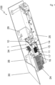
- Fig. 1 shows an overall view of the door drive 100, how it can be installed in a building, which should also include installation on ships and airplanes, and a door drive 100 of this type serves, for example, as a drive for an automatic sliding door system.
- the basic structure of the door drive 100 forms a support profile 30, which is shown shortened for easier viewing.
- the essential upper part of the L-shaped support profile 30 is shown cut away in order to make the other essential components of the door drive 100 visible.
- the door drive 100 has a motor unit 1 as a central component, and the motor unit 1 has the basic shape of a cuboid, which forms the housing 10 of the motor unit 1.
- a pulley 34 is arranged on the motor unit 1, over which a toothed belt can be placed, with which the connection to the wing element or elements, for example the glass sliding elements, is ultimately established , will be produced.
- the door drive 100 Adjacent to the motor unit 1, the door drive 100 has a power supply 24 and a controller 25, and the power supply 24 and the controller 25 are arranged on opposite sides of the motor unit 1.
- the motor unit 1 is attached to the support profile 30 with a first flange element 28, the first flange element 28 also receiving the power supply 24.
- the motor unit 1 is connected to the support profile 30 with a second flange element 29, the second flange element 29 also receiving the control 25.
- a single flange in order to accommodate at least the motor unit 1, the power supply 24 and the controller 25; there is also the possibility that the motor unit, the power supply 24 and/or the controller 25 each have associated separate flange elements for arrangement in or on the carrier profile 30.
- a window-like recess 14 is made in the housing 10 of the motor unit 1 on the front side surface, and the stator 11 has a surface section 15 which projects into the window-like recess 14. According to the invention, this creates the possibility of advantageously dissipating heat from the stator 11, since the stator 11 can be brought into heat-conducting contact with at least one further element via the surface section 15. For example, the stator 11 has been brought into heat-conducting contact with an inside of the carrier profile 30 by means of a further surface section, the further surface section being present on the rear side of the housing 10 of the motor unit 1 opposite the front, visible surface section 15.
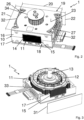
- FIGS. 2 and 3 each show a perspective view of the isolated motor unit 1, and in Figure 2 the housing 10 is shown with both housing halves 16 and 17, whereas in Figure 3 only the lower housing half 17 is shown, and the upper housing half 16 was removed from the illustration to illustrate the stator 11 and the rotor 12 with the output shaft 13.
- the shape of the housing 10 forms a cuboid, and the cuboid is determined by the longitudinal edge 20, the width edge 21 and the height edge 22, the side surfaces 26, 27 being spanned by the width edge 21 and the height edge 22. All edges 20, 21, 22 are perpendicular to each other.
- the side surfaces 26 and 27, to which the flange elements 28, 29 according to Figure 1 are attached, are designed with cooling fins 32.
- the surface of the surface sections 15 can be flush with the outside of the front and rear surfaces of the housing 10 in a common plane.
- the outward-facing surface section 15 of the stator 11 serves for heat-transferring contact with another body, for example with the carrier profile 30 or with another, separate heat sink.
- the stator 11 can be brought into direct heat-transferring contact with a motor conversion part, for example with the carrier profile 30 or with a separate heat sink.
- a heat transfer agent 31 for example in the form of a heat pad, can be arranged in front of the surface of the housing 10 with the window-like recess 14, the size of the heat transfer agent 31 also being able to be adapted, for example, to the area size of the surface section 15 of the stator 11.
- the pulley 34 for coupling a toothed belt is located on the top side of the illustration above the end face 23 of the housing 10, which is stretched over the longitudinal edge 20 and the width edge 21.
- the stator 11 is accommodated in a receiving recess within the lower, second housing half 17. Within the lower housing half 17, but also in a manner not shown in the upper housing half 16, there is a substantially annular receiving area in which the stator 11 is accommodated.
- the heat transfer gap 33 is an at least partially circumferential annular gap between the outside of the stator 11 and the inner surface of the receiving area and has small gap dimensions in order to heat the stator 11 via the housing halves 16, 17.
- the stator 11 heats up by energizing the winding (not shown) on the stator 11, and the heat from the stator 11 can pass into the housing halves 16, 17 with the very small heat transfer gap 33, for example if the heat transfer gap 33 has a transition fit.
- the heat transfer gap 33 is therefore advantageously designed as a transition fit.
- the circuit board 35 is attached to the outside of the housing 10 of the motor unit 1 with holding elements.
- Figure 4 shows a cross-sectional view of the arrangement of the motor unit 1 in or on the support profile 30 of the door drive 100.
- the arrangement is designed such that in the later operating position of the door drive 100, the output shaft 13 runs horizontally, which is connected to the rotor 12 and on which the Pulley 34 is applied.
- the movement space for the runner 36 is located within the support profile 30, and a wing element of the door system can be arranged on the support profile, for example a glass element of an automatic sliding door system.
- the rotor 36 is guided with rollers 37 on a rail 38 in the support profile 30, and in a manner not shown in detail, the rotor 36 is coupled for movement to the pulley 34 via a toothed belt.
- stator 11 of the motor unit 1 which is accommodated within the housing 10, adjoins the inside of the carrier profile 30, with a surface section 15 of the stator 11 adjoining the carrier profile 30, in particular via the heat transfer means 31.
- the surface section 15 of the stator 11 forms a flat surface on the outside of the stator 11, so that heat transfer can take place via a surface created in this way.
- the stator 11 has two flat surface sections 15 on its outer peripheral side, the underside surface section 15 being used to arrange a heat sink, not shown.
Landscapes
- Engineering & Computer Science (AREA)
- Power Engineering (AREA)
- Physics & Mathematics (AREA)
- Thermal Sciences (AREA)
- Power-Operated Mechanisms For Wings (AREA)
Claims (14)
- Entraînement de porte (100) pour un agencement sur ou en combinaison avec un système de porte, avec lequel au moins un élément de battant du système de porte peut être déplacé, présentant une unité moteur (1) avec un boîtier (10), dans lequel un stator (11) est logé au repos et dans lequel un rotor (12) est agencé rotatif dans le boîtier (10), qui présente un arbre de sortie (13), dans lequel l'arbre de sortie (13) peut être amené en liaison fonctionnelle par entraînement avec l'élément de battant, dans lequel l'entraînement de porte comprend un profilé de support (30),
caractérisé en ce que le boîtier (10) présente au moins un évidement (14) en forme de fenêtre, dans lequel fait saillie une section de surface (15) du stator (11), et dans lequel l'unité moteur (1) est agencée par rapport au profilé de support (30) de l'entraînement de porte (100) de telle sorte qu'une des sections de surface (15) du stator (11) est amenée au moins indirectement en contact de conduction thermique avec le profilé de support (30). - Entraînement de porte (100) selon la revendication 1, caractérisé en ce que le boîtier (10) de l'unité moteur (1) présente deux moitiés de boîtier (16, 17) qui sont reliées au moins indirectement l'une à l'autre, qui, une fois reliées l'une à l'autre, forment un parallélépipède rectangle.
- Entraînement de porte (100) selon la revendication 1 ou 2, caractérisé en ce que les moitiés de boîtier (16, 17) sont vissées ensemble au moins indirectement de manière adjacente l'une à l'autre et/ou dans lequel le boîtier (10) présente des évidements (14) en forme de fenêtre sur les côtés extérieurs (18, 19) opposés.
- Entraînement de porte (100) selon l'une des revendications 1 à 3, caractérisé en ce que l'unité moteur (1) est définie par un bord en longueur (20), un bord en largeur (21) et un bord en hauteur (22), dans lequel le bord en longueur (20) est plus grand que le bord en largeur (21) et/ou dans lequel le bord en largeur (21) est plus grand que le bord en hauteur (22).
- Entraînement de porte (100) selon la revendication 4, caractérisé en ce que le bord en longueur (20) et le bord en largeur (21) s'étendent sur une face frontale (23), dans lequel l'arbre de sortie (13) fait saillie verticalement depuis la face frontale (23).
- Entraînement de porte (100) selon la revendication 4 ou 5, caractérisé en ce qu'il est prévu au moins une alimentation électrique (24) et une commande (25), dans lequel l'alimentation électrique (24) et la commande (25) sont agencés au moins indirectement sur des surfaces latérales (26, 27) opposées, qui s'étendent sur le bord en largeur (21) et le bord en hauteur (22).
- Entraînement de porte (100) selon la revendication 6, caractérisé en ce qu'il est prévu un premier élément de bride (28), qui est agencé sur la première surface latérale (26) et reçoit en particulier l'alimentation électrique (24), et qu'il est prévu un second élément de bride (29), qui est agencé sur la seconde surface latérale (27) et reçoit en particulier la commande (25), dans lequel l'unité moteur (1) est maintenue dans l'entraînement de porte (100) par l'intermédiaire des deux éléments de bride (28, 29).
- Entraînement de porte (100) selon l'une des revendications précédentes, caractérisé en ce qu'un corps de base de l'entraînement de porte (100) est formé au moyen du profilé de support (30), dans lequel l'unité moteur (1) est alignée avec le profilé de support (30) par rapport à une position d'installation prête à l'emploi de telle sorte que l'arbre de sortie (13) présente une extension horizontale dans l'état de fonctionnement de l'entraînement de porte (100).
- Entraînement de porte (100) selon la revendication 8, caractérisé en ce que les éléments de bride (28, 29) sont fixés au profilé de support (30), de telle sorte que l'unité moteur (1) est agencée sur le profilé de support (30) au moyen des éléments de bride (28, 29).
- Entraînement de porte (100) selon l'une des revendications précédentes, caractérisé en ce qu'un moyen de transfert de chaleur (31) de forme plate est agencé entre la section de surface (15) du stator (11) et la section de surface du profilé de support (30) pour former le contact de conduction thermique.
- Entraînement de porte (100) selon l'une des revendications précédentes, caractérisé en ce que les surfaces latérales opposées (26, 27), qui s'étendent sur le bord en largeur (21) et le bord en hauteur (22), sont conçues pour être fermés et/ou présentent des ailettes de refroidissement (32).
- Entraînement de porte (100) selon l'une des revendications précédentes, caractérisé en ce qu'au moins une section de surface (15) du stator (11) est amenée en contact de transfert de chaleur avec un dissipateur thermique séparé à travers l'évidement (14) en forme de fenêtre.
- Entraînement de porte (100) selon l'une des revendications précédentes, caractérisé en ce que le stator (11) présente une structure de base annulaire et est reçu dans au moins une des moitiés de boîtier (16, 17), dans lequel une fente de transfert de chaleur (33) au moins partiellement circonférentielle est formée entre le côté extérieur radial du stator (11) et le côté intérieur de la moitié de boîtier (16, 17).
- Système de porte comportant un entraînement de porte (100) selon l'une des revendications précédentes, présentant au moins un élément de liaison pour la liaison avec un battant et/ou un élément de battant, avec lequel l'entraînement de porte (100) est en liaison fonctionnelle.
Priority Applications (3)
| Application Number | Priority Date | Filing Date | Title |
|---|---|---|---|
| ES19214426T ES2978789T3 (es) | 2019-12-09 | 2019-12-09 | Accionamiento de puerta con unidad de motor de pequeño tamaño |
| EP19214426.9A EP3835533B1 (fr) | 2019-12-09 | 2019-12-09 | Entrainement de porte doté d'une unité moteur à faible encombrement |
| PCT/EP2020/083347 WO2021115786A1 (fr) | 2019-12-09 | 2020-11-25 | Entraînement de porte doté d'une unité moteur ayant une petite taille d'installation |
Applications Claiming Priority (1)
| Application Number | Priority Date | Filing Date | Title |
|---|---|---|---|
| EP19214426.9A EP3835533B1 (fr) | 2019-12-09 | 2019-12-09 | Entrainement de porte doté d'une unité moteur à faible encombrement |
Publications (3)
| Publication Number | Publication Date |
|---|---|
| EP3835533A1 EP3835533A1 (fr) | 2021-06-16 |
| EP3835533B1 true EP3835533B1 (fr) | 2024-03-06 |
| EP3835533C0 EP3835533C0 (fr) | 2024-03-06 |
Family
ID=68840902
Family Applications (1)
| Application Number | Title | Priority Date | Filing Date |
|---|---|---|---|
| EP19214426.9A Active EP3835533B1 (fr) | 2019-12-09 | 2019-12-09 | Entrainement de porte doté d'une unité moteur à faible encombrement |
Country Status (3)
| Country | Link |
|---|---|
| EP (1) | EP3835533B1 (fr) |
| ES (1) | ES2978789T3 (fr) |
| WO (1) | WO2021115786A1 (fr) |
Family Cites Families (4)
| Publication number | Priority date | Publication date | Assignee | Title |
|---|---|---|---|---|
| DE10154156A1 (de) * | 2001-11-03 | 2003-05-15 | Bosch Gmbh Robert | Luftgekühlte elektrische Maschine |
| DE102008046062A1 (de) | 2008-09-08 | 2010-03-11 | Dorma Gmbh + Co. Kg | Nachrüstsatz mit einer Antriebseinheit, insbesondere für eine automatische Schiebetür |
| DE102014115932A1 (de) | 2014-10-31 | 2016-05-04 | Dorma Deutschland Gmbh | Türantrieb |
| US11139722B2 (en) * | 2018-03-02 | 2021-10-05 | Black & Decker Inc. | Motor having an external heat sink for a power tool |
-
2019
- 2019-12-09 ES ES19214426T patent/ES2978789T3/es active Active
- 2019-12-09 EP EP19214426.9A patent/EP3835533B1/fr active Active
-
2020
- 2020-11-25 WO PCT/EP2020/083347 patent/WO2021115786A1/fr not_active Ceased
Also Published As
| Publication number | Publication date |
|---|---|
| EP3835533A1 (fr) | 2021-06-16 |
| EP3835533C0 (fr) | 2024-03-06 |
| WO2021115786A1 (fr) | 2021-06-17 |
| ES2978789T3 (es) | 2024-09-20 |
Similar Documents
| Publication | Publication Date | Title |
|---|---|---|
| EP3574726B1 (fr) | Dispositif de refroidissement et dispositif de commande de robot équipé d'un tel dispositif de refroidissement | |
| DE102012214270B4 (de) | Schubkette, Antriebsvorrichtung zur linearen Bewegung sowie Untersuchungsbett | |
| DE60109874T2 (de) | Motorisierte Förderrolle | |
| DE69901695T2 (de) | Kühlelement für eine elektronische leistungsvorrichtung und eine elektronische leistungsvorrichtung mit einem solchen element | |
| DE4243044A1 (en) | Compact inverter integral type motor combination - has inverter cooled with heat sink mounted on top of hexagonal motor case, and cooling fan driven by motor drive shaft | |
| EP1907171B1 (fr) | Rail de guidage lineaire pour un systeme de guidage lineaire pourvu d'une rainure a fluide de refroidissement | |
| EP1066999B1 (fr) | Toit de véhicule | |
| DE3710198A1 (de) | Kuehlbare anordnung | |
| EP3835533B1 (fr) | Entrainement de porte doté d'une unité moteur à faible encombrement | |
| EP3835528B1 (fr) | Ensemble de porte doté d'une unité moteur, présentant une forme basique avantageuse | |
| DE3507255A1 (de) | Gehaeuse fuer elektrische bauteile | |
| EP3835534B1 (fr) | Entrainement de porte doté d'une unité moteur | |
| DE19543260A1 (de) | Elektrische Bauelementeanordnung mit mehreren in einem Gehäuse angeordneten elektrischen Bauelementen | |
| DE19951356A1 (de) | Unterflurcontainer für Schienenfahrzeuge | |
| EP3835529B1 (fr) | Entraînement de porte doté d'une unité moteur, comportant un agencement palier avantageux permettant de loger un arbre de sortie | |
| EP3835532B1 (fr) | Entrainement de porte doté d'une unité moteur d'une construction simple à densité d'intégration élevée | |
| EP3835531B1 (fr) | Entrainement de porte doté d'une unité moteur d'encombrement réduit haute performance | |
| EP4155111B1 (fr) | Boîtier de système d'un module d'axe électrique | |
| DE19942826C1 (de) | Gehäuse für elektronische Baugruppen | |
| DE102005051997B4 (de) | Tor | |
| DE10116872C2 (de) | Lüftermodul | |
| EP3835530B1 (fr) | Entrainement de porte doté d'une unité de moteur, comportant une connection électrique avantageux | |
| DE102023115394A1 (de) | Leiterplattensystem anschliessbar an eine gekapselte kühlung | |
| WO2024160415A1 (fr) | Dispositif de charge par induction fixe | |
| EP4525569A1 (fr) | Appareil de commutation |
Legal Events
| Date | Code | Title | Description |
|---|---|---|---|
| PUAI | Public reference made under article 153(3) epc to a published international application that has entered the european phase |
Free format text: ORIGINAL CODE: 0009012 |
|
| STAA | Information on the status of an ep patent application or granted ep patent |
Free format text: STATUS: THE APPLICATION HAS BEEN PUBLISHED |
|
| AK | Designated contracting states |
Kind code of ref document: A1 Designated state(s): AL AT BE BG CH CY CZ DE DK EE ES FI FR GB GR HR HU IE IS IT LI LT LU LV MC MK MT NL NO PL PT RO RS SE SI SK SM TR |
|
| STAA | Information on the status of an ep patent application or granted ep patent |
Free format text: STATUS: REQUEST FOR EXAMINATION WAS MADE |
|
| 17P | Request for examination filed |
Effective date: 20211215 |
|
| RBV | Designated contracting states (corrected) |
Designated state(s): AL AT BE BG CH CY CZ DE DK EE ES FI FR GB GR HR HU IE IS IT LI LT LU LV MC MK MT NL NO PL PT RO RS SE SI SK SM TR |
|
| GRAP | Despatch of communication of intention to grant a patent |
Free format text: ORIGINAL CODE: EPIDOSNIGR1 |
|
| STAA | Information on the status of an ep patent application or granted ep patent |
Free format text: STATUS: GRANT OF PATENT IS INTENDED |
|
| INTG | Intention to grant announced |
Effective date: 20231017 |
|
| GRAS | Grant fee paid |
Free format text: ORIGINAL CODE: EPIDOSNIGR3 |
|
| GRAA | (expected) grant |
Free format text: ORIGINAL CODE: 0009210 |
|
| STAA | Information on the status of an ep patent application or granted ep patent |
Free format text: STATUS: THE PATENT HAS BEEN GRANTED |
|
| AK | Designated contracting states |
Kind code of ref document: B1 Designated state(s): AL AT BE BG CH CY CZ DE DK EE ES FI FR GB GR HR HU IE IS IT LI LT LU LV MC MK MT NL NO PL PT RO RS SE SI SK SM TR |
|
| REG | Reference to a national code |
Ref country code: CH Ref legal event code: EP |
|
| REG | Reference to a national code |
Ref country code: IE Ref legal event code: FG4D Free format text: LANGUAGE OF EP DOCUMENT: GERMAN |
|
| REG | Reference to a national code |
Ref country code: DE Ref legal event code: R096 Ref document number: 502019010726 Country of ref document: DE |
|
| U01 | Request for unitary effect filed |
Effective date: 20240405 |
|
| U07 | Unitary effect registered |
Designated state(s): AT BE BG DE DK EE FI FR IT LT LU LV MT NL PT SE SI Effective date: 20240411 |
|
| PG25 | Lapsed in a contracting state [announced via postgrant information from national office to epo] |
Ref country code: GR Free format text: LAPSE BECAUSE OF FAILURE TO SUBMIT A TRANSLATION OF THE DESCRIPTION OR TO PAY THE FEE WITHIN THE PRESCRIBED TIME-LIMIT Effective date: 20240607 |
|
| PG25 | Lapsed in a contracting state [announced via postgrant information from national office to epo] |
Ref country code: RS Free format text: LAPSE BECAUSE OF FAILURE TO SUBMIT A TRANSLATION OF THE DESCRIPTION OR TO PAY THE FEE WITHIN THE PRESCRIBED TIME-LIMIT Effective date: 20240606 Ref country code: HR Free format text: LAPSE BECAUSE OF FAILURE TO SUBMIT A TRANSLATION OF THE DESCRIPTION OR TO PAY THE FEE WITHIN THE PRESCRIBED TIME-LIMIT Effective date: 20240306 |
|
| PG25 | Lapsed in a contracting state [announced via postgrant information from national office to epo] |
Ref country code: RS Free format text: LAPSE BECAUSE OF FAILURE TO SUBMIT A TRANSLATION OF THE DESCRIPTION OR TO PAY THE FEE WITHIN THE PRESCRIBED TIME-LIMIT Effective date: 20240606 Ref country code: NO Free format text: LAPSE BECAUSE OF FAILURE TO SUBMIT A TRANSLATION OF THE DESCRIPTION OR TO PAY THE FEE WITHIN THE PRESCRIBED TIME-LIMIT Effective date: 20240606 Ref country code: HR Free format text: LAPSE BECAUSE OF FAILURE TO SUBMIT A TRANSLATION OF THE DESCRIPTION OR TO PAY THE FEE WITHIN THE PRESCRIBED TIME-LIMIT Effective date: 20240306 Ref country code: GR Free format text: LAPSE BECAUSE OF FAILURE TO SUBMIT A TRANSLATION OF THE DESCRIPTION OR TO PAY THE FEE WITHIN THE PRESCRIBED TIME-LIMIT Effective date: 20240607 |
|
| REG | Reference to a national code |
Ref country code: ES Ref legal event code: FG2A Ref document number: 2978789 Country of ref document: ES Kind code of ref document: T3 Effective date: 20240920 |
|
| PG25 | Lapsed in a contracting state [announced via postgrant information from national office to epo] |
Ref country code: IS Free format text: LAPSE BECAUSE OF FAILURE TO SUBMIT A TRANSLATION OF THE DESCRIPTION OR TO PAY THE FEE WITHIN THE PRESCRIBED TIME-LIMIT Effective date: 20240706 |
|
| PG25 | Lapsed in a contracting state [announced via postgrant information from national office to epo] |
Ref country code: SM Free format text: LAPSE BECAUSE OF FAILURE TO SUBMIT A TRANSLATION OF THE DESCRIPTION OR TO PAY THE FEE WITHIN THE PRESCRIBED TIME-LIMIT Effective date: 20240306 |
|
| PG25 | Lapsed in a contracting state [announced via postgrant information from national office to epo] |
Ref country code: CZ Free format text: LAPSE BECAUSE OF FAILURE TO SUBMIT A TRANSLATION OF THE DESCRIPTION OR TO PAY THE FEE WITHIN THE PRESCRIBED TIME-LIMIT Effective date: 20240306 |
|
| PG25 | Lapsed in a contracting state [announced via postgrant information from national office to epo] |
Ref country code: PL Free format text: LAPSE BECAUSE OF FAILURE TO SUBMIT A TRANSLATION OF THE DESCRIPTION OR TO PAY THE FEE WITHIN THE PRESCRIBED TIME-LIMIT Effective date: 20240306 |
|
| PG25 | Lapsed in a contracting state [announced via postgrant information from national office to epo] |
Ref country code: SK Free format text: LAPSE BECAUSE OF FAILURE TO SUBMIT A TRANSLATION OF THE DESCRIPTION OR TO PAY THE FEE WITHIN THE PRESCRIBED TIME-LIMIT Effective date: 20240306 |
|
| PG25 | Lapsed in a contracting state [announced via postgrant information from national office to epo] |
Ref country code: SM Free format text: LAPSE BECAUSE OF FAILURE TO SUBMIT A TRANSLATION OF THE DESCRIPTION OR TO PAY THE FEE WITHIN THE PRESCRIBED TIME-LIMIT Effective date: 20240306 Ref country code: SK Free format text: LAPSE BECAUSE OF FAILURE TO SUBMIT A TRANSLATION OF THE DESCRIPTION OR TO PAY THE FEE WITHIN THE PRESCRIBED TIME-LIMIT Effective date: 20240306 Ref country code: RO Free format text: LAPSE BECAUSE OF FAILURE TO SUBMIT A TRANSLATION OF THE DESCRIPTION OR TO PAY THE FEE WITHIN THE PRESCRIBED TIME-LIMIT Effective date: 20240306 Ref country code: PL Free format text: LAPSE BECAUSE OF FAILURE TO SUBMIT A TRANSLATION OF THE DESCRIPTION OR TO PAY THE FEE WITHIN THE PRESCRIBED TIME-LIMIT Effective date: 20240306 Ref country code: IS Free format text: LAPSE BECAUSE OF FAILURE TO SUBMIT A TRANSLATION OF THE DESCRIPTION OR TO PAY THE FEE WITHIN THE PRESCRIBED TIME-LIMIT Effective date: 20240706 Ref country code: CZ Free format text: LAPSE BECAUSE OF FAILURE TO SUBMIT A TRANSLATION OF THE DESCRIPTION OR TO PAY THE FEE WITHIN THE PRESCRIBED TIME-LIMIT Effective date: 20240306 |
|
| REG | Reference to a national code |
Ref country code: DE Ref legal event code: R097 Ref document number: 502019010726 Country of ref document: DE |
|
| PLBE | No opposition filed within time limit |
Free format text: ORIGINAL CODE: 0009261 |
|
| STAA | Information on the status of an ep patent application or granted ep patent |
Free format text: STATUS: NO OPPOSITION FILED WITHIN TIME LIMIT |
|
| U20 | Renewal fee for the european patent with unitary effect paid |
Year of fee payment: 6 Effective date: 20241227 |
|
| 26N | No opposition filed |
Effective date: 20241209 |
|
| PG25 | Lapsed in a contracting state [announced via postgrant information from national office to epo] |
Ref country code: MC Free format text: LAPSE BECAUSE OF FAILURE TO SUBMIT A TRANSLATION OF THE DESCRIPTION OR TO PAY THE FEE WITHIN THE PRESCRIBED TIME-LIMIT Effective date: 20240306 |
|
| PG25 | Lapsed in a contracting state [announced via postgrant information from national office to epo] |
Ref country code: IE Free format text: LAPSE BECAUSE OF NON-PAYMENT OF DUE FEES Effective date: 20241209 |
|
| REG | Reference to a national code |
Ref country code: CH Ref legal event code: U11 Free format text: ST27 STATUS EVENT CODE: U-0-0-U10-U11 (AS PROVIDED BY THE NATIONAL OFFICE) Effective date: 20260101 |
|
| PGFP | Annual fee paid to national office [announced via postgrant information from national office to epo] |
Ref country code: GB Payment date: 20251219 Year of fee payment: 7 |
|
| U20 | Renewal fee for the european patent with unitary effect paid |
Year of fee payment: 7 Effective date: 20251230 |
|
| PGFP | Annual fee paid to national office [announced via postgrant information from national office to epo] |
Ref country code: ES Payment date: 20260130 Year of fee payment: 7 |
|
| PGFP | Annual fee paid to national office [announced via postgrant information from national office to epo] |
Ref country code: CH Payment date: 20260101 Year of fee payment: 7 |