EP1907712B1 - Verfahren zum befestigen eines zubehörteils an einer mauer und befestigungssatz hierfür - Google Patents
Verfahren zum befestigen eines zubehörteils an einer mauer und befestigungssatz hierfür Download PDFInfo
- Publication number
- EP1907712B1 EP1907712B1 EP06792521A EP06792521A EP1907712B1 EP 1907712 B1 EP1907712 B1 EP 1907712B1 EP 06792521 A EP06792521 A EP 06792521A EP 06792521 A EP06792521 A EP 06792521A EP 1907712 B1 EP1907712 B1 EP 1907712B1
- Authority
- EP
- European Patent Office
- Prior art keywords
- splitter
- anchor
- accessory
- accessory part
- piece
- Prior art date
- Legal status (The legal status is an assumption and is not a legal conclusion. Google has not performed a legal analysis and makes no representation as to the accuracy of the status listed.)
- Expired - Lifetime
Links
Images


Classifications
-
- F—MECHANICAL ENGINEERING; LIGHTING; HEATING; WEAPONS; BLASTING
- F16—ENGINEERING ELEMENTS AND UNITS; GENERAL MEASURES FOR PRODUCING AND MAINTAINING EFFECTIVE FUNCTIONING OF MACHINES OR INSTALLATIONS; THERMAL INSULATION IN GENERAL
- F16B—DEVICES FOR FASTENING OR SECURING CONSTRUCTIONAL ELEMENTS OR MACHINE PARTS TOGETHER, e.g. NAILS, BOLTS, CIRCLIPS, CLAMPS, CLIPS OR WEDGES; JOINTS OR JOINTING
- F16B33/00—Features common to bolt and nut
- F16B33/002—Means for preventing rotation of screw-threaded elements
-
- E—FIXED CONSTRUCTIONS
- E05—LOCKS; KEYS; WINDOW OR DOOR FITTINGS; SAFES
- E05B—LOCKS; ACCESSORIES THEREFOR; HANDCUFFS
- E05B1/00—Knobs or handles for wings; Knobs, handles, or press buttons for locks or latches on wings
- E05B1/0015—Knobs or handles which do not operate the bolt or lock, e.g. non-movable; Mounting thereof
-
- E—FIXED CONSTRUCTIONS
- E05—LOCKS; KEYS; WINDOW OR DOOR FITTINGS; SAFES
- E05B—LOCKS; ACCESSORIES THEREFOR; HANDCUFFS
- E05B9/00—Lock casings or latch-mechanism casings ; Fastening locks or fasteners or parts thereof to the wing
- E05B9/08—Fastening locks or fasteners or parts thereof, e.g. the casings of latch-bolt locks or cylinder locks to the wing
-
- F—MECHANICAL ENGINEERING; LIGHTING; HEATING; WEAPONS; BLASTING
- F16—ENGINEERING ELEMENTS AND UNITS; GENERAL MEASURES FOR PRODUCING AND MAINTAINING EFFECTIVE FUNCTIONING OF MACHINES OR INSTALLATIONS; THERMAL INSULATION IN GENERAL
- F16B—DEVICES FOR FASTENING OR SECURING CONSTRUCTIONAL ELEMENTS OR MACHINE PARTS TOGETHER, e.g. NAILS, BOLTS, CIRCLIPS, CLAMPS, CLIPS OR WEDGES; JOINTS OR JOINTING
- F16B13/00—Dowels or other devices fastened in walls or the like by inserting them in holes made therein for that purpose
- F16B13/04—Dowels or other devices fastened in walls or the like by inserting them in holes made therein for that purpose with parts gripping in the hole or behind the reverse side of the wall after inserting from the front
- F16B13/08—Dowels or other devices fastened in walls or the like by inserting them in holes made therein for that purpose with parts gripping in the hole or behind the reverse side of the wall after inserting from the front with separate or non-separate gripping parts moved into their final position in relation to the body of the device without further manual operation
- F16B13/0833—Dowels or other devices fastened in walls or the like by inserting them in holes made therein for that purpose with parts gripping in the hole or behind the reverse side of the wall after inserting from the front with separate or non-separate gripping parts moved into their final position in relation to the body of the device without further manual operation with segments or fingers expanding or tilting into an undercut hole
-
- E—FIXED CONSTRUCTIONS
- E05—LOCKS; KEYS; WINDOW OR DOOR FITTINGS; SAFES
- E05D—HINGES OR SUSPENSION DEVICES FOR DOORS, WINDOWS OR WINGS
- E05D5/00—Construction of single parts, e.g. the parts for attachment
- E05D5/02—Parts for attachment, e.g. flaps
- E05D5/0215—Parts for attachment, e.g. flaps for attachment to profile members or the like
- E05D5/0223—Parts for attachment, e.g. flaps for attachment to profile members or the like with parts, e.g. screws, extending through the profile wall or engaging profile grooves
- E05D5/023—Parts for attachment, e.g. flaps for attachment to profile members or the like with parts, e.g. screws, extending through the profile wall or engaging profile grooves with parts extending through the profile wall
-
- F—MECHANICAL ENGINEERING; LIGHTING; HEATING; WEAPONS; BLASTING
- F16—ENGINEERING ELEMENTS AND UNITS; GENERAL MEASURES FOR PRODUCING AND MAINTAINING EFFECTIVE FUNCTIONING OF MACHINES OR INSTALLATIONS; THERMAL INSULATION IN GENERAL
- F16B—DEVICES FOR FASTENING OR SECURING CONSTRUCTIONAL ELEMENTS OR MACHINE PARTS TOGETHER, e.g. NAILS, BOLTS, CIRCLIPS, CLAMPS, CLIPS OR WEDGES; JOINTS OR JOINTING
- F16B13/00—Dowels or other devices fastened in walls or the like by inserting them in holes made therein for that purpose
- F16B13/04—Dowels or other devices fastened in walls or the like by inserting them in holes made therein for that purpose with parts gripping in the hole or behind the reverse side of the wall after inserting from the front
- F16B13/08—Dowels or other devices fastened in walls or the like by inserting them in holes made therein for that purpose with parts gripping in the hole or behind the reverse side of the wall after inserting from the front with separate or non-separate gripping parts moved into their final position in relation to the body of the device without further manual operation
- F16B13/0858—Dowels or other devices fastened in walls or the like by inserting them in holes made therein for that purpose with parts gripping in the hole or behind the reverse side of the wall after inserting from the front with separate or non-separate gripping parts moved into their final position in relation to the body of the device without further manual operation with an expansible sleeve or dowel body driven against a tapered or spherical expander plug
-
- F—MECHANICAL ENGINEERING; LIGHTING; HEATING; WEAPONS; BLASTING
- F16—ENGINEERING ELEMENTS AND UNITS; GENERAL MEASURES FOR PRODUCING AND MAINTAINING EFFECTIVE FUNCTIONING OF MACHINES OR INSTALLATIONS; THERMAL INSULATION IN GENERAL
- F16B—DEVICES FOR FASTENING OR SECURING CONSTRUCTIONAL ELEMENTS OR MACHINE PARTS TOGETHER, e.g. NAILS, BOLTS, CIRCLIPS, CLAMPS, CLIPS OR WEDGES; JOINTS OR JOINTING
- F16B19/00—Bolts without screw-thread; Pins, including deformable elements; Rivets
- F16B19/04—Rivets; Spigots or the like fastened by riveting
- F16B19/08—Hollow rivets; Multi-part rivets
- F16B19/10—Hollow rivets; Multi-part rivets fastened by expanding mechanically
- F16B19/1027—Multi-part rivets
- F16B19/1036—Blind rivets
- F16B19/1045—Blind rivets fastened by a pull - mandrel or the like
- F16B19/1063—Blind rivets fastened by a pull - mandrel or the like with a sleeve or collar sliding over the hollow rivet body during the pulling operation
Definitions
- the present invention relates to a method of fixing an accessory part to a wall through at least one hole provided therein and to a fixture set therefor comprising an accessory part, and at least one means for fixing the accessory part to a front surface of a wall through a hole provided through said wall.
- the fixing means comprises an anchor, a bolt screwed into the anchor and a splitter arranged between the head of the bolt and the anchor.
- the anchor is entirely inserted in the hole in the wall and comprises at least two parts which are radially expandable by the splitter, when tightening the bolt, to lock the anchor against the back surface of the wall.
- Both the splitter and the anchor comprise mutually interlockable structures for substantially restricting rotation of the anchor relative to the splitter.
- the fixture set is especially intended to fix accessories to one of the walls of a hollow frame or more generally to a plate-like wall, the back side of which is not accessible. Fixing accessories to such a wall constitutes a well known problem.
- Fixing devices comprising a threaded bolt and an anchor, the anchor being insertable through a hole in the wall and threaded so as to be screwable to the bolt, whereas special means are provided to expand the anchor and restrict its rotation when screwing the bolt to the anchor, so that the anchor locks against the back surface of the wall.
- This fixing device comprises a bolt having a bolt head and an at least partially threaded shaft.
- the bolt is screwed in an anchor which is sized for being completely insertable through a hole in the wall and which comprises radially expandable parts.
- the fixing device further comprises a splitter which is interposed between the bolt head and the anchor, and which is sized for being partially axially insertable through the hole in the wall.
- the splitter and the anchor are shaped so as to restrict the rotation of the anchor relative to the splitter and to radially expand the expandable parts of the anchor when said splitter is urged to penetrate in between these parts when tightening the bolt until the free ends of the expandable parts engage the back surface of the wall.
- the fixing device is characterised in that it optionally comprises an intermediate accessory piece arranged to be fixed between the accessory part and the front surface of said wall, and the accessory part or the intermediate accessory piece comprises means for substantially restricting rotation of said splitter relative to said accessory part or intermediate accessory piece.
- the optional intermediate accessory piece is for example in the form of a plate-like piece which is interposed between the back side of the accessory piece and the wall to which the accessory part is to be fixed.
- the optionally intermediate accessory piece may be fixed, for example by screwing or welding, to the back of the accessory piece so that only the accessory part has to be held against the wall. Even when not fixed to the accessory part, the intermediate accessory piece can be held easily together with the accessory part to the wall, especially when two or more fixing means are provided since these fixing means prevent any rotation of the intermediate accessory piece with respect to the accessory part.
- said splitter comprises a non-circular portion, in particular a head portion
- said means for substantially restricting rotation of said splitter relative to said accessory part or to said intermediate accessory piece comprises a form-locking device for holding said non-circular portion of the splitter against rotation.
- said splitter head is square. This has the advantage of simplicity. However, any other suitable substantially flat-sided, preferably regular, configuration, like triangular, hexagonal or octagonal would be suitable.
- said form-locking device is a non-circular recess in said accessory part or in said intermediate accessory piece which is arranged to receive the head of the splitter.
- the recess can be obtained by providing ribs on the back side of the accessory part or of the intermediate accessory piece, which ribs may even be interrupted so that only some projections remain which define the recess and which restrict the rotation of the splitter.
- said principal advantage of this embodiment would be simplicity.
- said non-circular recess could be an elongated groove.
- the accessory part could be cheaply produced in an extrusion process and one recess could receive several splitter heads.
- said means for substantially restricting rotation comprise a solid connection to the splitter, the splitter preferably being an integral part of the accessory part or of the intermediate accessory piece and in particular formed in one piece with the accessory part or with the intermediate accessory piece.
- the hole in the accessory part has a widened inlet opening wherein the bolt head can be accommodated. This has the advantage of allowing a flat, protrusion-free surface on the mounted accessory part.
- the bolt is externally threaded and the anchor is internally threaded.
- This arrangement has the advantage of simplicity, although an alternative embodiment in which the bolt comprises an internally threaded axial bore, and the anchor an externally threaded shaft is also possible.
- said splitter may comprise at least one rib provided to engage in at least one slit on said anchor to substantially restrict rotation of said anchor and splitter relative to each other.
- the splitter is a moulded piece, made of a plastic material but preferably of a cast metal such as zamac.
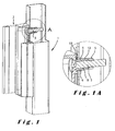
- FIG. 1 illustrates an example of a fixture set according to the invention fixed onto a wall of a hollow post or frame 1.
- This fixture set comprises an accessory part 2, which, in the non limiting example represented in this drawing, consists of a door keeper/bolt reception element, fixed against the front surface of one of the walls of the hollow frame 1.
- the accessory part 2 is fixed to the hollow frame 1 by means of two fixing means which extend through a hole 6 in said wall.
- Each of the fixing means comprises a standard externally threaded bolt 3, a splitter 4 (which is in this case a part separate from the accessory part), and an internally threaded anchor 5.
- the anchor 5 in its expanded position is held by the bolt 3, by means of the screw thread, against the inside surface of the wall, thus anchoring the whole fixture set.
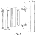
- FIG 2 shows an exploded view of the elements of assembly of figure 1 , before assembly.
- the screw threads of the bolt 3 and the anchor 5, which were not shown in the schematic representation of figure 1 are visible in the exploded view of figure 2 .
- the anchors 5, in their unexpanded form can be inserted in the circular holes 6 drilled in the wall of the hollow frame 1 whilst the splitters 4 can only be partially inserted in these holes 6.
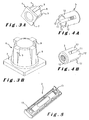
- the splitter 4 and the anchor 5 are shown in more detail in figures 3A and 3B and in figures 4A and 4B respectively.
- the splitter 4 comprises a non circular portion, more particularly a non-circular head 7, in this case square, which is larger than the holes 6 in the hollow frame.
- the portion of the splitter 4 which is inserted into the hollow frame has conical wedge surfaces 8 separated by ribs 9.
- the illustrated anchor 5 globally consists of a hollow cylinder comprising a threaded bottom part 10, with four slits 11 forming parts 12 which can be radially expanded by means of the splitter 4.
- the splitter 4 and anchor 5 are shaped so that, when urged against each other, the ribs 9 of the splitter 4 engage the slits 11 of the anchor 5, substantially restricting rotation of the anchor 5 relative to the splitter 4, and the conical wedge surfaces 8 of the splitter 4 force the expandable parts 12 of the anchor 5 outwards, thus expanding the outer diameter of the anchor 5 to a size lager than the diameter of the holes 6 in the hollow frame.
- the back side of the accessory part 2 comprises two square recesses 13 arranged to receive the square heads 7 of two splitters 4.
- their form-locking engagement substantially restricts rotation of the splitters 4 relative to the accessory part 2.
- the recesses are illustrated as square, any non-circular form that would restrict rotation of the splitter heads 7 could be considered.
- the non-circular portion of the splitter could also be formed of two or more projections onto the splitter which are received in corresponding recesses in the accessory part. Since there are two or more projections, each of them may even be circular.
- the recess 13 in the accessory part may, for instance, also be formed by a single elongated groove which can accommodate several splitter heads 7 and hold them against rotation.
- a single elongated groove which can accommodate several splitter heads 7 and hold them against rotation.
- the accessory part 2 is a bolt
- Figure 7 wherein the accessory part 2 is a hinge part used to fix a door closer, by means of pivots 14, to a hollow gate frame 1 and to a hollow gate post 1.
- the hinge parts 2, or similar hinge parts can also be used to hinge for example the gate itself to the post.
- An advantage of making the recesses 13 in the form of an elongated groove is that such a groove can easily be obtained when producing the accessory part by an extrusion process.
- Figures 8 and 9 illustrate another embodiment of the fixture set according to the invention wherein the accessory part 2 comprises a clamp 15 which is to be fixed to hollow fence post and which is arranged to fix grill panels 16 in an aesthetic and very reliable way to the fence posts.
- the bolts 3 are first introduced through holes in the accessory part 2, and then assembled with the splitters 4 and the anchors 5; the square heads 7 of the splitters thereby fit into the square recess 13 or elongated groove of the accessory part 2.
- the fixture set comprising the accessory part 2, bolts 3, splitters 4 and anchors 5 is then placed onto the front surface of the wall of the frame 1, with the fixing means introduced through the corresponding holes 6 in the wall.
- FIG. 11 An embodiment is illustrated in Figure 11 .
- two splitters 4 are integrally formed (in one piece) with the accessory part 2.
- the splitters and the accessory part are more particularly moulded in a die, for example injection moulded from a plastic material or produced by metal casting or forging.
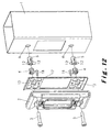
- FIG 12 illustrates another alternative, in which an intermediate accessory piece 17 is fixed by means of two screws 18 to the back side of the actual accessory part 2.
- This accessory part 2 is a bolt reception element for a sliding door (as described in US 6931897 ) and is made of quite robust steel material.
- the recesses 13 are provided in the intermediate accessory piece 17 which is arranged between the back of the accessory part 2 and the wall of the hollow post 1 to which it is to be fixed.
- the intermediate accessory piece has edges which coincide with the edges of the accessory part so that it can easily be held together with the accessory part, even if it would not be fixed to the accessory part.
- the intermediate accessory piece 17 is positioned by these fixing means in the right position with respect of the accessory part, even if it would have a different shape.
- the intermediate accessory piece may be moulded in a die, in particular of a plastic material or of metal, and the splitters 4 of the fixing means may be solidly connected to the intermediate accessory piece, in particular by forming (more particularly moulding) them in one piece or by fixing the splitters 4 by a welding process or mechanically, for example by means of screws, to the intermediate accessory piece.
- the recesses in the back side of the accessory part 2 or in the intermediate accessory piece 17 can for example be formed by ribs or ridges, which may even be interrupted provided they still restrict the rotation of the splitter with respect to the accessory part 2 or the intermediate accessory piece 17.
Landscapes
- Engineering & Computer Science (AREA)
- General Engineering & Computer Science (AREA)
- Mechanical Engineering (AREA)
- Connection Of Plates (AREA)
- Forms Removed On Construction Sites Or Auxiliary Members Thereof (AREA)
- Joining Of Building Structures In Genera (AREA)
- Adornments (AREA)
- Road Signs Or Road Markings (AREA)
Claims (17)
- Ein Verfahren zum Befestigen eines Zubehörteils (2) an einer Wand durch zumindest ein darin vorgesehenes Loch, wobei die Wand eine Vorder- und eine Rückseite hat und das Verfahren die folgenden Schritte umfasst:- Vorsehen eines Befestigungssatzes, welcher das Zubehörteil (2) und zumindest ein Mittel zur Befestigung des Zubehörteils (2) an der Vorderseite der Wand umfasst, wobei das Befestigungsmittel Folgendes umfasst:- einen Bolzen (3) mit einem Bolzenkopf und einem zumindest teilweise mit einem Gewinde versehenen Schaft;- einen Anker (5), der mit einem Gewinde versehen ist, um auf das Bolzenschaftgewinde geschraubt werden zu können, und der zumindest zwei Teile umfasst, die radial spreizbar sind; und- einen Spalter (4),
wobei der Spalter (4) und/oder der Anker (5) zumindest eine Keilfläche (8) umfassen, um die erwähnten radial spreizbaren Teile des erwähnten Ankers (5) radial zu spreizen, wenn der erwähnte Spalter (4) zum Eindringen zwischen die radial spreizbaren Teile des Ankers (5) gezwungen wird, und wobei der Spalter (4) und der Anker (5) ferner ineinander greifende Strukturen (9, 11) umfassen, um die Rotation des erwähnten Ankers (5) in Bezug auf den erwähnten Spalter (4) substanziell zu begrenzen,- Einführen des erwähnten Bolzenschafts durch ein Loch im Zubehörteil (2) und durch eine Öffnung im Spalter (4);- Anschrauben des Ankers (5) an den Bolzenschaft, sodass der Spalter zwischen dem Bolzenkopf und dem Anker (5) eingeschoben ist;- Montieren des Zubehörteils (2) an die Vorderseite der Wand, um das zusammengebaute Befestigungsmittel in das erwähnte Loch (6) durch die Wand einzuführen;- Anziehen des Bolzens (3), während die Rotation des Ankers (5) in Bezug auf den Spalter (4) mittels der erwähnten ineinander greifenden Strukturen (9, 11) substanziell begrenzt wird, um den Spalter (4) zum Eindringen zwischen die radial spreizbaren Teile des Ankers (5) zu zwingen, sodass die radial spreizbaren Teile des Ankers (5) zumindest teilweise gespreizt sind, wodurch der Anker gegen die Rückseite der Wand arretiert wird,dadurch gekennzeichnet, dass
beim Befestigen des Zubehörteils (2) an der Wand optional ein Zwischenzubehörstück (17) zwischen dem Zubehörteil (2) und der Vorderseite der Wand fixiert wird, und
dass die Rotation des Spalters (4) in Bezug auf das Zubehörteil (2) oder auf das optionale Zwischenzubehörstück (17) substanziell begrenzt ist, wenn der Bolzen (3) angezogen wird, indem ein Zubehörteil (2) oder ein optionales Zwischenzubehörstück (17) verwendet wird, das Mittel zur substanziellen Begrenzung der Rotation des Spalters (4) in Bezug auf das Zubehörteil (2) oder auf das optionale Zwischenzubehörstück (17) umfasst,- wobei das Mittel eine nicht runde Aussparung (13) im Zubehörteil (2) oder im optionalen Zwischenzubehörstück (17) umfasst, in die ein nicht runder Abschnitt (7) des Spalters (4), wobei der Spalter (4) ein vom Zubehörteil (2) und vom optionalen Zwischenzubehörstück (17) getrenntes Teil ist, aufgenommen ist, um den nicht runden Spalterabschnitt (7) gegen Rotation zu halten, oder- wobei das Mittel eine feste Verbindung zwischen dem Zubehörteil (2) oder dem optionalen Zwischenzubehörstück (17) und dem Spalter (4) umfasst. - Ein Verfahren nach Anspruch 1, dadurch gekennzeichnet, dass der erwähnte Spalter ein vom Zubehörteil (2) und vom optionalen Zwischenzubehörstück (17) getrenntes Teil ist, wobei der Spalter (4) mit seinem nicht runden Abschnitt (7) in die nicht runde Aussparung (13) im Zubehörteil (2) oder im optionalen Zwischenzubehörstück (17) eingeführt wird, bevor das Zubehörteil (2) gegen die Vorderseite der Wand platziert wird.
- Ein Verfahren nach Anspruch 2, dadurch gekennzeichnet, dass der Spalter (4) mit seinem nicht runden Abschnitt (7) von der Rückseite des Zubehörteils (2) in die nicht runde Aussparung (13) eingebracht wird, die in der Rückseite des Zubehörteils (2) vorgesehen ist.
- Ein Verfahren nach Anspruch 1, dadurch gekennzeichnet, dass der Spalter fest mit dem Zubehörteil (2) oder dem optionalen Zwischenzubehörstück (17) verbunden ist, wobei diese feste Verbindung erreicht wird, indem das Zubehörteil (2) oder das optionale Zwischenzubehörstück (17) in einem Stück mit dem Spalter geformt ist, indem der Spalter (4) auf das Zubehörteil (2) oder das optionale Zwischenzubehörstück (17) geschweißt ist, oder indem der Spalter (4) mittels Schrauben daran befestigt ist.
- Ein Befestigungssatz zur Verwendung in einem Verfahren nach jedem der Ansprüche 1 bis 4, welcher ein Zubehörteil (2) mit zumindest einem Loch und zumindest einem Mittel zur Befestigung des Zubehörteils (2) an einer Vorderseite einer Wand durch ein in der erwähnten Wand vorgesehenes Loch umfasst, wobei das Befestigungsmittel Folgendes umfasst:- einen Bolzen (3) mit einem Bolzenkopf und einem zumindest teilweise mit einem Gewinde versehenen Schaft, wobei der Bolzen dazu geeignet ist, durch das Loch im Zubehörteil eingeführt zu werden;- einen Anker (5), der mit einem Gewinde versehen ist, um auf das Bolzenschaftgewinde geschraubt werden zu können, das dimensioniert ist, um axial durch das erwähnte Loch in der Wand eingeführt werden zu können, und der zumindest zwei Teile umfasst, die radial spreizbar sind, um den Anker gegen eine Rückseite der erwähnten Wand zu arretieren;- einen Spalter (4), der eine Öffnung umfasst, angeordnet, um den Bolzenschaft aufzunehmen, sodass der Spalter zwischen den Bolzenkopf und den Anker (5) eingeschoben werden kann, und der dimensioniert ist, um zumindest teilweise axial durch das Loch in der Wand eingeschoben werden zu können und zwischen die radial spreizbaren Teile des Ankers eindringen zu können;wobei der Spalter (4) und/oder der Anker (5) zumindest eine Keilfläche (8) umfassen, um die erwähnten radial spreizbaren Teile des erwähnten Ankers (5) radial zu spreizen, wenn der erwähnte Spalter (4) zum Eindringen zwischen die radial spreizbaren Teile des Ankers (5) gezwungen wird, insbesondere durch Anziehen des erwähnten Bolzen (3), und wobei der Spalter (4) und der Anker (5) ferner ineinander greifende Strukturen (9, 11) umfassen, um die Rotation des erwähnten Ankers (5) in Bezug auf den erwähnten Spalter (4) substanziell zu begrenzen, insbesondere wenn der Bolzen (3) auf den Anker (5) geschraubt wird;
dadurch gekennzeichnet, dass der Befestigungssatz optional ein Zwischenzubehörstück (17) umfasst, angeordnet, um zwischen dem Zubehörteil (2) und der Vorderseite der erwähnten Wand befestigt zu werden, und dadurch, dass das Zubehörteil (2) oder das optionale Zwischenzubehörstück Mittel zur substanziellen Begrenzung der Rotation des erwähnten Spalters (4) in Bezug auf das erwähnte Zubehörteil (2) oder optionale Zwischenzubehörstück (17) umfasst,- wobei das Mittel einen nicht runden Abschnitt (7) des Spalters (4) umfasst, wobei der Spalter (4) ein vom Zubehörteil (2) und vom optionalen Zwischenzubehörstück (17) getrenntes Teil ist, sowie eine nicht runde Aussparung (13) im Zubehörteil (2) oder im optionalen Zwischenzubehörstück (17), wobei die Aussparung (13) angeordnet ist, um den nicht runden Abschnitt (7) des Spalters (4) aufzunehmen und um den nicht runden Spalterabschnitt (7) gegen Rotation zu halten, oder- wobei das Mittel eine feste Verbindung zwischen dem Zubehörteil (2) oder dem Zwischenzubehörstück (17) und dem Spalter (4) umfasst. - Ein Befestigungssatz nach Anspruch 5, wobei der erwähnte nicht runde Abschnitt (7) des Spalters (4) ein nicht runder Kopfabschnitt ist.
- Ein Befestigungssatz nach Anspruch 5 oder 6, wobei der erwähnte nicht runde Splitterabschnitt (7) viereckig ist, insbesondere substanziell quadratisch.
- Ein Befestigungssatz nach jedem der Ansprüche 5 bis 7, wobei die erwähnte nicht runde Aussparung (13) eine längliche Nut ist.
- Ein Befestigungssatz nach jedem der vorigen Ansprüche, der zumindest zwei der erwähnten Befestigungsmittel umfasst.
- Ein Befestigungssatz nach Anspruch 5, wobei der Spalter (4) ein fixer Bestandteil des Zubehörteils (2) oder des Zwischenzubehörstücks ist und insbesondere in einem Stück mit dem Zubehörteil (2) oder dem Zwischenzubehörstück geformt ist.
- Ein Befestigungssatz nach den Ansprüchen 9 und 10, wobei das erwähnte Zubehörteil (2) oder das erwähnte Zwischenzubehörstück (17) mit zumindest zwei Spaltern (4) versehen ist.
- Ein Befestigungssatz nach jedem der vorigen Ansprüche 5 bis 11, wobei ein Loch im Zubehörteil (2) eine erweiterte Einlassöffnung hat, in der der Bolzenkopf untergebracht werden kann.
- Ein Befestigungssatz nach jedem der vorigen Ansprüche 5 bis 12, wobei die erwähnte Keilfläche (8) konisch ist.
- Ein Befestigungssatz nach jedem der vorigen Ansprüche 5 bis 13, wobei der Spalter (4) erwähnte zumindest eine Keilfläche (8) umfasst.
- Ein Befestigungssatz nach jedem der vorigen Ansprüche 5 bis 14, wobei die erwähnten ersten ineinander greifenden Strukturen (9, 11) zumindest einen Schlitz (11) zwischen den radial spreizbaren Teilen des erwähnten Ankers (5) und zumindest eine Rippe (9) auf dem erwähnten Spalter (4) umfassen, um in erwähnten zumindest einen Schlitz (11) einzugreifen.
- Ein Befestigungssatz nach Anspruch 15, wobei der Anker (5) aus einem substanziell zylindrischen oder prismatoiden Teil mit zwei Grundflächen, einer länglichen Bohrung zwischen den erwähnten zwei Grundflächen besteht, wobei die erwähnte Bohrung zumindest teilweise mit einem Gewinde versehen ist, und die erwähnten Schlitze (11) den Anker (5) teilweise von einer seiner Grundflächen durchlaufen.
- Ein Befestigungssatz nach jedem der vorigen Ansprüche 5 bis 16, wobei das erwähnte Zubehörteil (2) ein Zubehörteil umfasst, ausgewählt aus der Gruppe bestehend aus einem Türschließblech, einer Montageklemme, einem Scharnierteil, einem Element zur Aufnahme eines Schlossriegels, einem Riegel und einem Montagerahmen zur Montage eines zusätzlichen Teils.
Priority Applications (2)
| Application Number | Priority Date | Filing Date | Title |
|---|---|---|---|
| EP06792521A EP1907712B1 (de) | 2005-07-20 | 2006-07-19 | Verfahren zum befestigen eines zubehörteils an einer mauer und befestigungssatz hierfür |
| PL06792521T PL1907712T3 (pl) | 2005-07-20 | 2006-07-19 | Sposób mocowania elementu osprzętu do ściany oraz zespół mocujący |
Applications Claiming Priority (3)
| Application Number | Priority Date | Filing Date | Title |
|---|---|---|---|
| EP05106649A EP1746293A1 (de) | 2005-07-20 | 2005-07-20 | Befestigungsvorrichtung für Hohlrahmen und ebene Flächen |
| EP06792521A EP1907712B1 (de) | 2005-07-20 | 2006-07-19 | Verfahren zum befestigen eines zubehörteils an einer mauer und befestigungssatz hierfür |
| PCT/EP2006/064391 WO2007009998A1 (en) | 2005-07-20 | 2006-07-19 | Fixture set |
Publications (2)
| Publication Number | Publication Date |
|---|---|
| EP1907712A1 EP1907712A1 (de) | 2008-04-09 |
| EP1907712B1 true EP1907712B1 (de) | 2008-12-17 |
Family
ID=35448047
Family Applications (2)
| Application Number | Title | Priority Date | Filing Date |
|---|---|---|---|
| EP05106649A Withdrawn EP1746293A1 (de) | 2005-07-20 | 2005-07-20 | Befestigungsvorrichtung für Hohlrahmen und ebene Flächen |
| EP06792521A Expired - Lifetime EP1907712B1 (de) | 2005-07-20 | 2006-07-19 | Verfahren zum befestigen eines zubehörteils an einer mauer und befestigungssatz hierfür |
Family Applications Before (1)
| Application Number | Title | Priority Date | Filing Date |
|---|---|---|---|
| EP05106649A Withdrawn EP1746293A1 (de) | 2005-07-20 | 2005-07-20 | Befestigungsvorrichtung für Hohlrahmen und ebene Flächen |
Country Status (11)
| Country | Link |
|---|---|
| US (3) | US7780387B2 (de) |
| EP (2) | EP1746293A1 (de) |
| AT (1) | ATE418014T1 (de) |
| AU (1) | AU2006271636B2 (de) |
| CA (1) | CA2615932A1 (de) |
| DE (1) | DE602006004347D1 (de) |
| DK (1) | DK1907712T3 (de) |
| ES (1) | ES2319933T3 (de) |
| PL (1) | PL1907712T3 (de) |
| PT (1) | PT1907712E (de) |
| WO (1) | WO2007009998A1 (de) |
Cited By (12)
| Publication number | Priority date | Publication date | Assignee | Title |
|---|---|---|---|---|
| EP3342969A1 (de) | 2016-12-27 | 2018-07-04 | Locinox | Hydraulisch gedämpfter aktuator und selbstschliessendes scharnier mit dem aktuator |
| EP3342965A1 (de) | 2016-12-27 | 2018-07-04 | Locinox | Hydraulisch gedämpftes, selbstschliessendes scharnier |
| WO2018122210A1 (en) | 2016-12-27 | 2018-07-05 | Locinox | Hydraulically damped actuator and self-closing hinge comprising the actuator |
| WO2018121890A1 (en) | 2016-12-27 | 2018-07-05 | Locinox | A hydraulically damped actuator |
| WO2018228729A1 (en) | 2017-06-16 | 2018-12-20 | Locinox | A hydraulically damped actuator |
| EP3421693A1 (de) | 2017-06-26 | 2019-01-02 | Locinox | Elektrischer türöffner |
| EP3421697A1 (de) | 2017-06-26 | 2019-01-02 | Locinox | Elektrischer türöffner |
| EP3421694A1 (de) | 2017-06-26 | 2019-01-02 | Locinox | Oberflächenmontierbarer, elektrischer türöffner |
| WO2021170871A1 (en) | 2020-02-28 | 2021-09-02 | Locinox | A dashpot for damping a closing movement of a closure system |
| WO2021170870A1 (en) | 2020-02-28 | 2021-09-02 | Locinox | A hydraulically damped hinge for hinging a closure member to a support |
| WO2023031172A1 (en) | 2021-08-30 | 2023-03-09 | Locinox | A hydraulically damped hinge and a method of assembling the same |
| EP4159958A1 (de) | 2021-10-01 | 2023-04-05 | Locinox | Schliessblech und verfahren zur herstellung eines schliessblechs |
Families Citing this family (51)
| Publication number | Priority date | Publication date | Assignee | Title |
|---|---|---|---|---|
| US20090019812A1 (en) * | 2007-07-18 | 2009-01-22 | Steve Getz | Anchoring Apparatus and Method |
| US20100172713A1 (en) * | 2008-12-30 | 2010-07-08 | Michael Louis Benson | Self locking floating fastener |
| EP3147520B1 (de) * | 2009-03-13 | 2021-05-26 | Centrix Inc. | Blind-befestigungselement mit integrierter antirotationsfunktion |
| IT1395804B1 (it) * | 2009-09-17 | 2012-10-26 | Gsg Int Spa | Cerniera ad attacco frontale per infissi. |
| DE202012104332U1 (de) * | 2012-11-12 | 2012-11-28 | SCHÜCO International KG | Griffelement für eine Frontplatte für Möbel |
| PL2749720T3 (pl) | 2012-12-27 | 2018-10-31 | Joseph Talpe | Elektryczne urządzenie ryglujące z zabezpieczonym przed uszkodzeniem odblokowywaniem awaryjnym |
| US10401825B2 (en) * | 2013-01-31 | 2019-09-03 | Hewlett Packard Enterprise Development Lp | Area occupancy information extraction |
| CN103133496B (zh) * | 2013-03-07 | 2015-02-18 | 安徽江淮汽车股份有限公司 | 一种卡扣式螺母组件 |
| JP6164646B2 (ja) * | 2013-10-22 | 2017-07-19 | 住友林業株式会社 | 柱脚部接合構造 |
| US10296483B2 (en) * | 2014-01-03 | 2019-05-21 | Phoenix Contact Development and Manufacturing, Inc. | Fieldbus network with two-wire loop |
| US9217278B2 (en) * | 2014-04-14 | 2015-12-22 | Eastern Wholesale Fence Co. Inc. | Truss anchor and truss assembly used for reinforcing gate |
| GB2529634B (en) | 2014-08-26 | 2017-04-19 | Kwikbolt Ltd | Removable blind fastener for joining components |
| US10323419B2 (en) | 2015-04-16 | 2019-06-18 | Fero Corporation | Support bracket apparatus |
| US9316004B1 (en) | 2014-12-01 | 2016-04-19 | Michael Hatzinikolas | Support bracket assembly and method |
| CN104864227A (zh) * | 2015-06-03 | 2015-08-26 | 马鞍山聚力科技有限公司 | 一种太阳能光伏抽水泵的安装装置 |
| BE1023032B1 (nl) | 2015-10-06 | 2016-11-09 | Locinox Nv | Deursloteenheid die ingericht is om te worden gemonteerd op een buisvormig element |
| DE102016112014A1 (de) * | 2016-06-30 | 2018-01-04 | Böllhoff Verbindungstechnik GmbH | Befestiger mit Dämpfungsfunktion |
| WO2018169956A1 (en) | 2017-03-13 | 2018-09-20 | Herman Miller, Inc. | Subarchitectural office system |
| BE1025033B1 (nl) * | 2017-09-05 | 2018-10-03 | Locinox Nv | Oogboutscharnier en daarmee op steun bevestigde poort |
| DE202018101902U1 (de) | 2018-04-09 | 2018-04-25 | LOCINOX (eine Gesellschaft nach belgischem Recht) | Augenschrauben-Scharnier und damit an Stütze befestigtes Tor |
| US10538913B2 (en) * | 2018-05-23 | 2020-01-21 | Herman Miller, Inc. | Connection assembly for an architectural structure |
| EP3575617B1 (de) * | 2018-05-31 | 2021-03-24 | Locinox | Befestigungssatz |
| US11255091B2 (en) | 2018-12-03 | 2022-02-22 | Fero Corporation | Support bracket apparatus |
| US11118358B2 (en) | 2019-05-30 | 2021-09-14 | Fero Corporation | Support bracket assembly and method |
| CA3107451A1 (en) | 2020-01-31 | 2021-07-31 | Mitek Holdings, Inc. | Facade support system |
| US11162265B2 (en) | 2020-04-06 | 2021-11-02 | Fero Corporation | Support bracket assembly and method |
| EP3907418B1 (de) | 2020-05-04 | 2023-07-12 | Locinox | Schliessdämpfer zur dämpfung einer schliessbewegung eines scharnierverschlusssystems |
| CN112081455A (zh) * | 2020-09-04 | 2020-12-15 | 广东坚朗五金制品股份有限公司 | 执手组件及门窗系统 |
| WO2022069516A1 (en) * | 2020-09-30 | 2022-04-07 | Industrilås I Nässjö Ab | Door handle and/or locking arrangement comprising an expanding sleeve |
| CN112832483B (zh) * | 2020-12-31 | 2022-03-22 | 浙江万川装饰设计工程有限公司 | 一种装饰构件的安装结构及其施工方法 |
| US11674316B2 (en) | 2021-01-29 | 2023-06-13 | Hohmann & Barnard, Inc. | Facade support system |
| US11560709B2 (en) | 2021-06-11 | 2023-01-24 | Fero Corporation | Support bracket hanger assembly and method |
| PL4245951T3 (pl) | 2022-03-17 | 2025-01-13 | Locinox | Osprzęt zamka drzwiowego przystosowany do zamontowania na członie rurowym |
| EP4379254B1 (de) | 2022-12-01 | 2025-06-18 | Locinox | Aussenbeleuchtungsanordnung |
| EP4400684A1 (de) | 2023-01-13 | 2024-07-17 | Locinox | Torschliesser und verschlusssystem damit |
| EP4655512A1 (de) | 2023-01-25 | 2025-12-03 | Locinox | Befestigungsset |
| US12398568B2 (en) | 2023-04-25 | 2025-08-26 | Hohmann & Barnard, Inc. | Thermal brick support mounting bracket |
| BE1032121B1 (nl) | 2023-11-08 | 2025-06-10 | Locinox Nv | Een poortactuator |
| CN122161980A (zh) | 2023-10-05 | 2026-06-05 | 洛西诺克斯公司 | 门致动器 |
| BE1032033B1 (nl) | 2023-10-05 | 2025-05-12 | Locinox Nv | Een poortactuator |
| BE1032034B1 (nl) | 2023-10-05 | 2025-05-12 | Locinox Nv | Een poortactuator |
| BE1032036B1 (nl) | 2023-10-05 | 2025-05-12 | Locinox Nv | Een poortactuator |
| EP4610453A1 (de) | 2024-03-01 | 2025-09-03 | Locinox | Torpfosten |
| EP4610468A1 (de) | 2024-03-01 | 2025-09-03 | Locinox | Torpfosten |
| EP4610454A1 (de) | 2024-03-01 | 2025-09-03 | Locinox | Torpfosten |
| WO2025256732A1 (en) | 2024-06-11 | 2025-12-18 | Locinox | A push bar latch and an outdoor closure system comprising the same |
| EP4671486A1 (de) | 2024-06-25 | 2025-12-31 | Locinox | Torpfosten |
| EP4768691A1 (de) | 2024-12-30 | 2026-07-01 | Locinox | Verschlusssystem |
| EP4776507A1 (de) | 2025-01-14 | 2026-07-15 | Locinox | Elektrisch betriebener gate-aktuator |
| WO2026153985A1 (en) | 2025-01-14 | 2026-07-23 | Locinox | An electrically operated hinge |
| WO2026153984A1 (en) | 2025-01-14 | 2026-07-23 | Locinox | An electrically operated hinge |
Family Cites Families (82)
| Publication number | Priority date | Publication date | Assignee | Title |
|---|---|---|---|---|
| US1305001A (en) * | 1919-05-27 | ogden | ||
| US633537A (en) * | 1899-01-18 | 1899-09-19 | Roudolphus Peet | Leak-stopper. |
| US670922A (en) * | 1900-10-12 | 1901-03-26 | Joseph Marquardt | Expanding clamp. |
| US716273A (en) * | 1902-02-10 | 1902-12-16 | Charles L Peirce Jr | Expansible bolt-fastening device. |
| US877118A (en) * | 1906-12-24 | 1908-01-21 | Ralph S Peirce | Fastening device for masonry. |
| US927064A (en) * | 1908-11-14 | 1909-07-06 | Herbert W Mower | Expansion-bolt. |
| US1049376A (en) * | 1911-11-09 | 1913-01-07 | Nat Metal Molding Company | Bolt and screw retainer. |
| US1161155A (en) * | 1913-08-02 | 1915-11-23 | Henry B Newhall | Combined expansion and toggle bolt and parts thereof. |
| US1208999A (en) * | 1914-09-25 | 1916-12-19 | Norman Mellor | Wall-anchor. |
| US1153797A (en) * | 1915-04-29 | 1915-09-14 | Jules Emile Kegreisz | Expansion-anchor. |
| US1244992A (en) * | 1915-09-14 | 1917-10-30 | Joseph Lee | Expansion-bolt. |
| US1933536A (en) * | 1930-05-16 | 1933-11-07 | Floor Accessories Company Inc | Concrete insert |
| US1996121A (en) * | 1932-07-30 | 1935-04-02 | John H Phillips | Anchoring device |
| US1996128A (en) * | 1933-11-21 | 1935-04-02 | Dardelet Threadlock Corp | Fastener |
| USRE22543E (en) * | 1936-10-14 | 1944-09-05 | Fastening device | |
| US2143086A (en) * | 1938-03-02 | 1939-01-10 | Diamond Expansion Bolt Co Inc | Bolt anchor |
| US2542144A (en) * | 1945-01-01 | 1951-02-20 | Shellmar Products Corp | Blind rivet |
| US2670021A (en) * | 1949-06-03 | 1954-02-23 | Carel T Torresen | Die collapsed anchor nut |
| US2805597A (en) * | 1953-05-25 | 1957-09-10 | Preferred Engineering And Res | Expanding fastener for use with materials of varying thickness |
| US3181413A (en) * | 1959-05-15 | 1965-05-04 | Hi Shear Rivet Tool Company | Fastening device with lubricating means |
| US3172603A (en) * | 1960-11-16 | 1965-03-09 | Star Expansion Ind Corp | Anchoring device |
| US3180203A (en) * | 1963-03-28 | 1965-04-27 | Rudolph M Vaughn | Radially expandable two-piece blind fastener |
| US3365999A (en) * | 1966-05-26 | 1968-01-30 | United Shoe Machinery Corp | Screw-anchoring devices |
| US3449774A (en) * | 1967-02-01 | 1969-06-17 | American Standard Inc | Attachment device for toilet seat hinge |
| US3503584A (en) * | 1967-05-01 | 1970-03-31 | Allan F Erhart | Anchor stud holding assembly for concrete forms |
| US3469493A (en) * | 1968-02-14 | 1969-09-30 | Illinois Tool Works | Sealing device |
| AU450291B2 (en) * | 1968-07-31 | 1974-06-20 | W, A. Deutsher Proprietary Limited | Improved sealing and anchoring device |
| US3505921A (en) * | 1969-03-21 | 1970-04-14 | Illinois Tool Works | Fastening device |
| US3673913A (en) * | 1970-09-04 | 1972-07-04 | Southco | Panel fastener with expandable sleeve |
| US3739684A (en) * | 1971-11-12 | 1973-06-19 | J Vitkevich | Expansion hanger device |
| US3739683A (en) * | 1972-01-27 | 1973-06-19 | J Bishop | Expansion fastening device |
| DE2249762C3 (de) * | 1972-10-11 | 1980-05-08 | Heinrich 6102 Pfungstadt Liebig | Doppelt spreizender Dübel |
| CA988317A (en) * | 1973-02-28 | 1976-05-04 | Michel Bouchard | Anchoring device for securing and positioning equipment |
| JPS5922329B2 (ja) * | 1976-06-21 | 1984-05-25 | 株式会社ニフコ | コ−ド留め具 |
| FR2375480A1 (fr) * | 1976-12-21 | 1978-07-21 | Comet | Perfectionnements aux dispositifs de fixation |
| US4397595A (en) * | 1977-06-06 | 1983-08-09 | Dry Dock Industries, Inc. | Anchoring retainer for threaded fasteners |
| US4143581A (en) * | 1977-06-06 | 1979-03-13 | Dry Dock Industries, Inc. | Anchoring retainer for threaded fasteners |
| DE2754910A1 (de) * | 1977-12-09 | 1979-06-13 | Erich Mundhenke | Befestigungsvorrichtung zum einsetzen in eine aufnahme in einer wandung oder zum verbinden von aufnahmen aufweisenden elementen |
| EP0002654B1 (de) * | 1977-12-24 | 1982-01-20 | Heinrich Liebig | Dübel zur formschlüssigen Befestigung in einer hinterschnittenen Bohrung |
| US4182216A (en) * | 1978-03-02 | 1980-01-08 | Textron, Inc. | Collapsible threaded insert device for plastic workpieces |
| US4221154A (en) * | 1978-08-02 | 1980-09-09 | Mechanical Plastics Corp. | Fastening element with anti-jacking device |
| NL177510C (nl) * | 1978-11-22 | 1985-10-01 | Bridgestone Tire Co Ltd | Ankerkast bestemd om in beton ingebed te worden. |
| US4491447A (en) * | 1980-05-15 | 1985-01-01 | Dry Dock Industries, Inc. | Anchoring retainer for threaded fasteners |
| JPS5934732Y2 (ja) * | 1980-11-05 | 1984-09-26 | 株式会社ニフコ | 部品取付構造 |
| US4375342A (en) * | 1981-01-14 | 1983-03-01 | Phillips Plastic Corp. | Two-piece plastic fastener |
| US4412407A (en) * | 1981-06-15 | 1983-11-01 | Samuel T. Melfi | Mounting arrangement for guard rail post |
| US4613264A (en) * | 1982-04-16 | 1986-09-23 | Mcintyre Douglas O | Anchor bolt |
| US4530630A (en) * | 1982-07-14 | 1985-07-23 | Brown Russell L | Expanding anchor fastener |
| US4478542A (en) * | 1983-02-28 | 1984-10-23 | Whelan Jr Russell | Expansion anchor grip sleeve assembly |
| US4521148A (en) * | 1983-05-06 | 1985-06-04 | Nifco Inc. | Hinged mirror image plastic fastener for quick assembly to threaded male members |
| GB8405402D0 (en) * | 1984-03-01 | 1984-04-04 | Dom Holdings Plc | Expansion anchor |
| DE3503450A1 (de) | 1984-06-22 | 1986-01-02 | Decoletaje y Extrusion, S.A. (DESA), Hospitalet de Llobregat, Barcelona | Verankerungsbolzen mit aufweitbarer huelse |
| SE446763B (sv) * | 1984-12-20 | 1986-10-06 | Torsten Stig Danielsson | Festanordning for fixering av en skruv eller liknande i ett, foretredesvis i en gipsskiva, upptaget hal |
| US4598572A (en) * | 1985-02-04 | 1986-07-08 | Huck Manufacturing Company | Apparatus and gripping jaw assembly for setting fasteners |
| US4789282A (en) * | 1986-02-26 | 1988-12-06 | Abraham Frederic C | Expansion anchor stud |
| US4946325A (en) * | 1986-02-26 | 1990-08-07 | Abraham Frederic C | Expansion anchor stud |
| KR900001257B1 (ko) | 1987-01-31 | 1990-03-05 | 진인주 | 절단와샤를 이용한 체결구 |
| US4834601A (en) * | 1987-06-01 | 1989-05-30 | Klaas Schaap | Wall fastener |
| US5080542A (en) * | 1989-11-24 | 1992-01-14 | J. P. Sheahan & Associates, Inc. | Fastening and leak detector device and method for its use to secure roofs |
| US5120169A (en) * | 1991-10-09 | 1992-06-09 | Emhart Inc. | Blind fastener |
| US5205690A (en) * | 1992-03-23 | 1993-04-27 | Steven Roth | Concrete insert for attaching utility hangers to a structure |
| US5546723A (en) * | 1993-12-20 | 1996-08-20 | Harlen Metal Products, Inc. | Wood sill reinforcement plate |
| US5392573A (en) * | 1994-03-14 | 1995-02-28 | Gould; William W. | Concrete anchoring bolt |
| DE9422153U1 (de) * | 1994-09-14 | 1998-06-25 | TOX-Dübel-Werk Richard W. Heckhausen GmbH & Co KG, 78351 Bodman-Ludwigshafen | Dübeleinheit |
| US5890340A (en) * | 1996-08-29 | 1999-04-06 | Kafarowski; Zygmunt Grant | Concrete insert for attaching wall panels to building structures |
| US5813808A (en) * | 1996-10-28 | 1998-09-29 | Wu; Ming-Hsin | Expansion screw having overlapping expanding elements |
| JP3630260B2 (ja) * | 1997-03-05 | 2005-03-16 | アイシン精機株式会社 | 便座取り付け構造 |
| US5779085A (en) * | 1997-03-11 | 1998-07-14 | Gas Research Institute | Expandable pin plug for automated use |
| US6102641A (en) * | 1998-10-14 | 2000-08-15 | Hildebrandt; David J. | Hole plug |
| US6128883A (en) * | 1999-09-20 | 2000-10-10 | Lathico Industries | Brick anchor system |
| IT1319705B1 (it) * | 2000-12-21 | 2003-11-03 | Sergio Zambelli | Dispositivo di protezione di inserti di sollevamento a corpo tubolare,durante il loro inglobamento all'interno di un manufatto prefabbricato |
| JP2002289617A (ja) * | 2001-03-28 | 2002-10-04 | Mitsubishi Heavy Ind Ltd | 集積回路構造 |
| DE10134375A1 (de) * | 2001-07-14 | 2003-01-30 | Horst Filipp Gmbh | Verbindungseinrichtung |
| NL1019220C2 (nl) | 2001-10-24 | 2003-04-28 | Sun Bright Prec Ind | Expansieschroef. |
| US6893199B2 (en) * | 2001-11-26 | 2005-05-17 | Larry Michels | Sheer resistant fastener assembly |
| US6719509B1 (en) | 2002-10-04 | 2004-04-13 | Joker Ind Co Ltd | Expansion screw |
| DE10305610A1 (de) * | 2003-02-11 | 2004-08-19 | Ejot Gmbh & Co. Kg | Kunststoffmutter zur Aufnahme an einem einen Durchbruch aufweisenden Bauteil |
| US20040208722A1 (en) * | 2003-04-17 | 2004-10-21 | Pop-In Pop-Out, Inc. | Fastener adapted for use with a structural member |
| US20040208721A1 (en) * | 2003-04-17 | 2004-10-21 | Rainer Kuenzel | Fastener adapted for use with a structural member |
| US7661694B2 (en) * | 2003-08-18 | 2010-02-16 | Cequent Towing Products, Inc. | Towing assembly |
| JP4680776B2 (ja) * | 2003-11-25 | 2011-05-11 | 原田工業株式会社 | 車両用ルーフアンテナ取付け装置 |
| DE202005019615U1 (de) * | 2005-12-14 | 2006-04-13 | Allsafe Jungfalk Gmbh & Co. Kg | Befestigungselement |
-
2005
- 2005-07-20 EP EP05106649A patent/EP1746293A1/de not_active Withdrawn
-
2006
- 2006-07-19 ES ES06792521T patent/ES2319933T3/es not_active Expired - Lifetime
- 2006-07-19 WO PCT/EP2006/064391 patent/WO2007009998A1/en not_active Ceased
- 2006-07-19 PT PT06792521T patent/PT1907712E/pt unknown
- 2006-07-19 CA CA002615932A patent/CA2615932A1/en not_active Abandoned
- 2006-07-19 PL PL06792521T patent/PL1907712T3/pl unknown
- 2006-07-19 EP EP06792521A patent/EP1907712B1/de not_active Expired - Lifetime
- 2006-07-19 AT AT06792521T patent/ATE418014T1/de active
- 2006-07-19 DK DK06792521T patent/DK1907712T3/da active
- 2006-07-19 AU AU2006271636A patent/AU2006271636B2/en not_active Expired
- 2006-07-19 DE DE602006004347T patent/DE602006004347D1/de not_active Expired - Lifetime
- 2006-07-20 US US11/458,699 patent/US7780387B2/en active Active
-
2010
- 2010-07-08 US US12/832,610 patent/US20100275550A1/en not_active Abandoned
-
2011
- 2011-10-18 US US13/275,831 patent/US8333048B2/en not_active Expired - Lifetime
Cited By (17)
| Publication number | Priority date | Publication date | Assignee | Title |
|---|---|---|---|---|
| EP3342969A1 (de) | 2016-12-27 | 2018-07-04 | Locinox | Hydraulisch gedämpfter aktuator und selbstschliessendes scharnier mit dem aktuator |
| EP3342965A1 (de) | 2016-12-27 | 2018-07-04 | Locinox | Hydraulisch gedämpftes, selbstschliessendes scharnier |
| WO2018122210A1 (en) | 2016-12-27 | 2018-07-05 | Locinox | Hydraulically damped actuator and self-closing hinge comprising the actuator |
| WO2018122170A1 (en) | 2016-12-27 | 2018-07-05 | Locinox | Hydraulically damped, self closing hinge |
| WO2018121890A1 (en) | 2016-12-27 | 2018-07-05 | Locinox | A hydraulically damped actuator |
| WO2018228729A1 (en) | 2017-06-16 | 2018-12-20 | Locinox | A hydraulically damped actuator |
| EP4249718A2 (de) | 2017-06-16 | 2023-09-27 | Locinox | Hydraulisch gedämpfter aktuator |
| EP3421694A1 (de) | 2017-06-26 | 2019-01-02 | Locinox | Oberflächenmontierbarer, elektrischer türöffner |
| EP3421697A1 (de) | 2017-06-26 | 2019-01-02 | Locinox | Elektrischer türöffner |
| US11359411B2 (en) | 2017-06-26 | 2022-06-14 | Locinox | Surface-mountable electric strike |
| EP3421693A1 (de) | 2017-06-26 | 2019-01-02 | Locinox | Elektrischer türöffner |
| WO2021170871A1 (en) | 2020-02-28 | 2021-09-02 | Locinox | A dashpot for damping a closing movement of a closure system |
| WO2021170870A1 (en) | 2020-02-28 | 2021-09-02 | Locinox | A hydraulically damped hinge for hinging a closure member to a support |
| US12366100B2 (en) | 2020-02-28 | 2025-07-22 | Locinox | Hydraulically damped hinge for hinging a closure member to a support |
| US12421779B2 (en) | 2020-02-28 | 2025-09-23 | Locinox | Dashpot for damping a closing movement of a closure system |
| WO2023031172A1 (en) | 2021-08-30 | 2023-03-09 | Locinox | A hydraulically damped hinge and a method of assembling the same |
| EP4159958A1 (de) | 2021-10-01 | 2023-04-05 | Locinox | Schliessblech und verfahren zur herstellung eines schliessblechs |
Also Published As
| Publication number | Publication date |
|---|---|
| US8333048B2 (en) | 2012-12-18 |
| PL1907712T3 (pl) | 2009-07-31 |
| EP1907712A1 (de) | 2008-04-09 |
| AU2006271636A2 (en) | 2008-06-12 |
| EP1746293A1 (de) | 2007-01-24 |
| US20100275550A1 (en) | 2010-11-04 |
| ATE418014T1 (de) | 2009-01-15 |
| DE602006004347D1 (de) | 2009-01-29 |
| DK1907712T3 (da) | 2009-04-14 |
| WO2007009998A1 (en) | 2007-01-25 |
| US20070033895A1 (en) | 2007-02-15 |
| AU2006271636B2 (en) | 2011-06-23 |
| AU2006271636A1 (en) | 2007-01-25 |
| CA2615932A1 (en) | 2007-01-25 |
| PT1907712E (pt) | 2009-03-23 |
| US20120031037A1 (en) | 2012-02-09 |
| US7780387B2 (en) | 2010-08-24 |
| ES2319933T3 (es) | 2009-05-14 |
Similar Documents
| Publication | Publication Date | Title |
|---|---|---|
| US7780387B2 (en) | Fixture set | |
| US5810502A (en) | Screw fastener | |
| US5468109A (en) | Quick removable fasteners in particular for furniture | |
| US7059025B2 (en) | Fastener | |
| GB2546072B (en) | Attachment assembly and method of using same | |
| US5669105A (en) | Adjustable door hinge | |
| CA2841510A1 (en) | Adjustable anchor assembly for panels | |
| JP4451903B2 (ja) | パネルサポート | |
| US5855042A (en) | Door hinge assembly | |
| EP3608551A1 (de) | Klammeranker zur befestigung von schmiedewaren an ein hohlprofil eines fensters oder einer tür | |
| JPH0725450Y2 (ja) | 締着具 | |
| JP3025317U (ja) | レール受け具 | |
| GB2259243A (en) | Mounting bathroom accessories | |
| KR200203219Y1 (ko) | 보조 자물쇠의 플레이트 구조 | |
| EP1411197B1 (de) | Riegel | |
| JPH0941807A (ja) | ドア枠の取り付け構造 | |
| EP0035482B1 (de) | Verfahren zum ausrichtbaren Befestigen eines Rahmens oder dgl. in einer Öffnung und Sicherungsscheibe zur Durchführung des Verfahrens | |
| JP3022334U (ja) | レール受け具 | |
| KR200398021Y1 (ko) | 가구용 금속 부재의 직결볼트 구조 | |
| JPH0728388Y2 (ja) | 補強具 | |
| GB2153905A (en) | Hinge | |
| KR100349556B1 (ko) | 자동차용 스피커 | |
| JPH0512456Y2 (de) | ||
| AU725328B3 (en) | Fastener fixing device | |
| JP2000087459A (ja) | Alc用のアンカーと締結具及びその製造方法 |
Legal Events
| Date | Code | Title | Description |
|---|---|---|---|
| PUAI | Public reference made under article 153(3) epc to a published international application that has entered the european phase |
Free format text: ORIGINAL CODE: 0009012 |
|
| 17P | Request for examination filed |
Effective date: 20080214 |
|
| AK | Designated contracting states |
Kind code of ref document: A1 Designated state(s): AT BE BG CH CY CZ DE DK EE ES FI FR GB GR HU IE IS IT LI LT LU LV MC NL PL PT RO SE SI SK TR |
|
| RTI1 | Title (correction) |
Free format text: METHOD FOR FIXING AN ACCESSORY PART TO A WALL AND FIXTURE SET THEREFOR |
|
| GRAP | Despatch of communication of intention to grant a patent |
Free format text: ORIGINAL CODE: EPIDOSNIGR1 |
|
| GRAS | Grant fee paid |
Free format text: ORIGINAL CODE: EPIDOSNIGR3 |
|
| GRAA | (expected) grant |
Free format text: ORIGINAL CODE: 0009210 |
|
| AK | Designated contracting states |
Kind code of ref document: B1 Designated state(s): AT BE BG CH CY CZ DE DK EE ES FI FR GB GR HU IE IS IT LI LT LU LV MC NL PL PT RO SE SI SK TR |
|
| REG | Reference to a national code |
Ref country code: GB Ref legal event code: FG4D |
|
| REG | Reference to a national code |
Ref country code: CH Ref legal event code: EP |
|
| REG | Reference to a national code |
Ref country code: IE Ref legal event code: FG4D |
|
| REF | Corresponds to: |
Ref document number: 602006004347 Country of ref document: DE Date of ref document: 20090129 Kind code of ref document: P |
|
| REG | Reference to a national code |
Ref country code: PT Ref legal event code: SC4A Free format text: AVAILABILITY OF NATIONAL TRANSLATION Effective date: 20090313 |
|
| REG | Reference to a national code |
Ref country code: SE Ref legal event code: TRGR Ref country code: CH Ref legal event code: NV Representative=s name: DR. LUSUARDI AG |
|
| REG | Reference to a national code |
Ref country code: DK Ref legal event code: T3 |
|
| PG25 | Lapsed in a contracting state [announced via postgrant information from national office to epo] |
Ref country code: LT Free format text: LAPSE BECAUSE OF FAILURE TO SUBMIT A TRANSLATION OF THE DESCRIPTION OR TO PAY THE FEE WITHIN THE PRESCRIBED TIME-LIMIT Effective date: 20081217 |
|
| REG | Reference to a national code |
Ref country code: ES Ref legal event code: FG2A Ref document number: 2319933 Country of ref document: ES Kind code of ref document: T3 |
|
| PG25 | Lapsed in a contracting state [announced via postgrant information from national office to epo] |
Ref country code: SI Free format text: LAPSE BECAUSE OF FAILURE TO SUBMIT A TRANSLATION OF THE DESCRIPTION OR TO PAY THE FEE WITHIN THE PRESCRIBED TIME-LIMIT Effective date: 20081217 Ref country code: FI Free format text: LAPSE BECAUSE OF FAILURE TO SUBMIT A TRANSLATION OF THE DESCRIPTION OR TO PAY THE FEE WITHIN THE PRESCRIBED TIME-LIMIT Effective date: 20081217 Ref country code: LV Free format text: LAPSE BECAUSE OF FAILURE TO SUBMIT A TRANSLATION OF THE DESCRIPTION OR TO PAY THE FEE WITHIN THE PRESCRIBED TIME-LIMIT Effective date: 20081217 |
|
| PG25 | Lapsed in a contracting state [announced via postgrant information from national office to epo] |
Ref country code: EE Free format text: LAPSE BECAUSE OF FAILURE TO SUBMIT A TRANSLATION OF THE DESCRIPTION OR TO PAY THE FEE WITHIN THE PRESCRIBED TIME-LIMIT Effective date: 20081217 Ref country code: BG Free format text: LAPSE BECAUSE OF FAILURE TO SUBMIT A TRANSLATION OF THE DESCRIPTION OR TO PAY THE FEE WITHIN THE PRESCRIBED TIME-LIMIT Effective date: 20090317 Ref country code: RO Free format text: LAPSE BECAUSE OF FAILURE TO SUBMIT A TRANSLATION OF THE DESCRIPTION OR TO PAY THE FEE WITHIN THE PRESCRIBED TIME-LIMIT Effective date: 20081217 |
|
| REG | Reference to a national code |
Ref country code: PL Ref legal event code: T3 |
|
| PG25 | Lapsed in a contracting state [announced via postgrant information from national office to epo] |
Ref country code: IS Free format text: LAPSE BECAUSE OF FAILURE TO SUBMIT A TRANSLATION OF THE DESCRIPTION OR TO PAY THE FEE WITHIN THE PRESCRIBED TIME-LIMIT Effective date: 20090417 |
|
| PG25 | Lapsed in a contracting state [announced via postgrant information from national office to epo] |
Ref country code: SK Free format text: LAPSE BECAUSE OF FAILURE TO SUBMIT A TRANSLATION OF THE DESCRIPTION OR TO PAY THE FEE WITHIN THE PRESCRIBED TIME-LIMIT Effective date: 20081217 |
|
| PLBE | No opposition filed within time limit |
Free format text: ORIGINAL CODE: 0009261 |
|
| STAA | Information on the status of an ep patent application or granted ep patent |
Free format text: STATUS: NO OPPOSITION FILED WITHIN TIME LIMIT |
|
| 26N | No opposition filed |
Effective date: 20090918 |
|
| PG25 | Lapsed in a contracting state [announced via postgrant information from national office to epo] |
Ref country code: MC Free format text: LAPSE BECAUSE OF NON-PAYMENT OF DUE FEES Effective date: 20090731 |
|
| PG25 | Lapsed in a contracting state [announced via postgrant information from national office to epo] |
Ref country code: GR Free format text: LAPSE BECAUSE OF FAILURE TO SUBMIT A TRANSLATION OF THE DESCRIPTION OR TO PAY THE FEE WITHIN THE PRESCRIBED TIME-LIMIT Effective date: 20090318 |
|
| PGFP | Annual fee paid to national office [announced via postgrant information from national office to epo] |
Ref country code: TR Payment date: 20101214 Year of fee payment: 5 |
|
| PGFP | Annual fee paid to national office [announced via postgrant information from national office to epo] |
Ref country code: CZ Payment date: 20101231 Year of fee payment: 5 |
|
| PG25 | Lapsed in a contracting state [announced via postgrant information from national office to epo] |
Ref country code: HU Free format text: LAPSE BECAUSE OF FAILURE TO SUBMIT A TRANSLATION OF THE DESCRIPTION OR TO PAY THE FEE WITHIN THE PRESCRIBED TIME-LIMIT Effective date: 20090618 |
|
| PG25 | Lapsed in a contracting state [announced via postgrant information from national office to epo] |
Ref country code: CY Free format text: LAPSE BECAUSE OF FAILURE TO SUBMIT A TRANSLATION OF THE DESCRIPTION OR TO PAY THE FEE WITHIN THE PRESCRIBED TIME-LIMIT Effective date: 20081217 |
|
| PGFP | Annual fee paid to national office [announced via postgrant information from national office to epo] |
Ref country code: CH Payment date: 20111213 Year of fee payment: 6 Ref country code: IE Payment date: 20111129 Year of fee payment: 6 Ref country code: LU Payment date: 20111130 Year of fee payment: 6 Ref country code: DK Payment date: 20111129 Year of fee payment: 6 Ref country code: SE Payment date: 20111129 Year of fee payment: 6 |
|
| PG25 | Lapsed in a contracting state [announced via postgrant information from national office to epo] |
Ref country code: CZ Free format text: LAPSE BECAUSE OF NON-PAYMENT OF DUE FEES Effective date: 20110719 |
|
| PGFP | Annual fee paid to national office [announced via postgrant information from national office to epo] |
Ref country code: PT Payment date: 20120120 Year of fee payment: 7 |
|
| REG | Reference to a national code |
Ref country code: CH Ref legal event code: PL |
|
| REG | Reference to a national code |
Ref country code: SE Ref legal event code: EUG |
|
| REG | Reference to a national code |
Ref country code: DK Ref legal event code: EBP |
|
| PG25 | Lapsed in a contracting state [announced via postgrant information from national office to epo] |
Ref country code: CH Free format text: LAPSE BECAUSE OF NON-PAYMENT OF DUE FEES Effective date: 20120731 Ref country code: LI Free format text: LAPSE BECAUSE OF NON-PAYMENT OF DUE FEES Effective date: 20120731 Ref country code: SE Free format text: LAPSE BECAUSE OF NON-PAYMENT OF DUE FEES Effective date: 20120720 |
|
| REG | Reference to a national code |
Ref country code: IE Ref legal event code: MM4A |
|
| PG25 | Lapsed in a contracting state [announced via postgrant information from national office to epo] |
Ref country code: DK Free format text: LAPSE BECAUSE OF NON-PAYMENT OF DUE FEES Effective date: 20120731 Ref country code: IE Free format text: LAPSE BECAUSE OF NON-PAYMENT OF DUE FEES Effective date: 20120719 |
|
| REG | Reference to a national code |
Ref country code: PT Ref legal event code: MM4A Free format text: LAPSE DUE TO NON-PAYMENT OF FEES Effective date: 20140120 |
|
| PG25 | Lapsed in a contracting state [announced via postgrant information from national office to epo] |
Ref country code: TR Free format text: LAPSE BECAUSE OF NON-PAYMENT OF DUE FEES Effective date: 20120719 |
|
| PG25 | Lapsed in a contracting state [announced via postgrant information from national office to epo] |
Ref country code: LU Free format text: LAPSE BECAUSE OF NON-PAYMENT OF DUE FEES Effective date: 20120719 |
|
| PG25 | Lapsed in a contracting state [announced via postgrant information from national office to epo] |
Ref country code: PT Free format text: LAPSE BECAUSE OF NON-PAYMENT OF DUE FEES Effective date: 20140120 |
|
| REG | Reference to a national code |
Ref country code: FR Ref legal event code: PLFP Year of fee payment: 11 |
|
| REG | Reference to a national code |
Ref country code: FR Ref legal event code: PLFP Year of fee payment: 12 |
|
| REG | Reference to a national code |
Ref country code: FR Ref legal event code: PLFP Year of fee payment: 13 |
|
| REG | Reference to a national code |
Ref country code: BE Ref legal event code: PD Owner name: LOCINOX; BE Free format text: DETAILS ASSIGNMENT: CHANGE OF OWNER(S), CESSION Effective date: 20181210 |
|
| PGFP | Annual fee paid to national office [announced via postgrant information from national office to epo] |
Ref country code: PL Payment date: 20250626 Year of fee payment: 20 |
|
| PGFP | Annual fee paid to national office [announced via postgrant information from national office to epo] |
Ref country code: NL Payment date: 20250618 Year of fee payment: 20 Ref country code: BE Payment date: 20250618 Year of fee payment: 20 |
|
| PGFP | Annual fee paid to national office [announced via postgrant information from national office to epo] |
Ref country code: FR Payment date: 20250618 Year of fee payment: 20 |
|
| PGFP | Annual fee paid to national office [announced via postgrant information from national office to epo] |
Ref country code: ES Payment date: 20250811 Year of fee payment: 20 |
|
| PGFP | Annual fee paid to national office [announced via postgrant information from national office to epo] |
Ref country code: DE Payment date: 20250728 Year of fee payment: 20 |
|
| PGFP | Annual fee paid to national office [announced via postgrant information from national office to epo] |
Ref country code: IT Payment date: 20250721 Year of fee payment: 20 |
|
| PGFP | Annual fee paid to national office [announced via postgrant information from national office to epo] |
Ref country code: GB Payment date: 20250722 Year of fee payment: 20 |
|
| PGFP | Annual fee paid to national office [announced via postgrant information from national office to epo] |
Ref country code: AT Payment date: 20250718 Year of fee payment: 20 |
|
| REG | Reference to a national code |
Ref country code: DE Ref legal event code: R071 Ref document number: 602006004347 Country of ref document: DE |
|
| REG | Reference to a national code |
Ref country code: NL Ref legal event code: MK Effective date: 20260718 |
|
| REG | Reference to a national code |
Ref country code: ES Ref legal event code: FD2A Effective date: 20260730 |
|
| REG | Reference to a national code |
Ref country code: GB Ref legal event code: PE20 Expiry date: 20260718 |