EP1908972A2 - Dispositif de désaccouplement d'un roulement d'un arbre situé sur un corps de base, et ressort ondulé radial - Google Patents
Dispositif de désaccouplement d'un roulement d'un arbre situé sur un corps de base, et ressort ondulé radial Download PDFInfo
- Publication number
- EP1908972A2 EP1908972A2 EP08000885A EP08000885A EP1908972A2 EP 1908972 A2 EP1908972 A2 EP 1908972A2 EP 08000885 A EP08000885 A EP 08000885A EP 08000885 A EP08000885 A EP 08000885A EP 1908972 A2 EP1908972 A2 EP 1908972A2
- Authority
- EP
- European Patent Office
- Prior art keywords
- radial
- spring
- decoupling device
- radially
- wave spring
- Prior art date
- Legal status (The legal status is an assumption and is not a legal conclusion. Google has not performed a legal analysis and makes no representation as to the accuracy of the status listed.)
- Granted
Links
Images







Classifications
-
- F—MECHANICAL ENGINEERING; LIGHTING; HEATING; WEAPONS; BLASTING
- F16—ENGINEERING ELEMENTS AND UNITS; GENERAL MEASURES FOR PRODUCING AND MAINTAINING EFFECTIVE FUNCTIONING OF MACHINES OR INSTALLATIONS; THERMAL INSULATION IN GENERAL
- F16C—SHAFTS; FLEXIBLE SHAFTS; ELEMENTS OR CRANKSHAFT MECHANISMS; ROTARY BODIES OTHER THAN GEARING ELEMENTS; BEARINGS
- F16C27/00—Elastic or yielding bearings or bearing supports, for exclusively rotary movement
- F16C27/06—Elastic or yielding bearings or bearing supports, for exclusively rotary movement by means of parts of rubber or like materials
- F16C27/066—Ball or roller bearings
-
- F—MECHANICAL ENGINEERING; LIGHTING; HEATING; WEAPONS; BLASTING
- F16—ENGINEERING ELEMENTS AND UNITS; GENERAL MEASURES FOR PRODUCING AND MAINTAINING EFFECTIVE FUNCTIONING OF MACHINES OR INSTALLATIONS; THERMAL INSULATION IN GENERAL
- F16C—SHAFTS; FLEXIBLE SHAFTS; ELEMENTS OR CRANKSHAFT MECHANISMS; ROTARY BODIES OTHER THAN GEARING ELEMENTS; BEARINGS
- F16C25/00—Bearings for exclusively rotary movement adjustable for wear or play
- F16C25/06—Ball or roller bearings
- F16C25/08—Ball or roller bearings self-adjusting
-
- F—MECHANICAL ENGINEERING; LIGHTING; HEATING; WEAPONS; BLASTING
- F16—ENGINEERING ELEMENTS AND UNITS; GENERAL MEASURES FOR PRODUCING AND MAINTAINING EFFECTIVE FUNCTIONING OF MACHINES OR INSTALLATIONS; THERMAL INSULATION IN GENERAL
- F16C—SHAFTS; FLEXIBLE SHAFTS; ELEMENTS OR CRANKSHAFT MECHANISMS; ROTARY BODIES OTHER THAN GEARING ELEMENTS; BEARINGS
- F16C27/00—Elastic or yielding bearings or bearing supports, for exclusively rotary movement
- F16C27/04—Ball or roller bearings, e.g. with resilient rolling bodies
-
- F—MECHANICAL ENGINEERING; LIGHTING; HEATING; WEAPONS; BLASTING
- F16—ENGINEERING ELEMENTS AND UNITS; GENERAL MEASURES FOR PRODUCING AND MAINTAINING EFFECTIVE FUNCTIONING OF MACHINES OR INSTALLATIONS; THERMAL INSULATION IN GENERAL
- F16C—SHAFTS; FLEXIBLE SHAFTS; ELEMENTS OR CRANKSHAFT MECHANISMS; ROTARY BODIES OTHER THAN GEARING ELEMENTS; BEARINGS
- F16C19/00—Bearings with rolling contact, for exclusively rotary movement
- F16C19/02—Bearings with rolling contact, for exclusively rotary movement with bearing balls essentially of the same size in one or more circular rows
- F16C19/04—Bearings with rolling contact, for exclusively rotary movement with bearing balls essentially of the same size in one or more circular rows for radial load mainly
- F16C19/06—Bearings with rolling contact, for exclusively rotary movement with bearing balls essentially of the same size in one or more circular rows for radial load mainly with a single row or balls
-
- F—MECHANICAL ENGINEERING; LIGHTING; HEATING; WEAPONS; BLASTING
- F16—ENGINEERING ELEMENTS AND UNITS; GENERAL MEASURES FOR PRODUCING AND MAINTAINING EFFECTIVE FUNCTIONING OF MACHINES OR INSTALLATIONS; THERMAL INSULATION IN GENERAL
- F16C—SHAFTS; FLEXIBLE SHAFTS; ELEMENTS OR CRANKSHAFT MECHANISMS; ROTARY BODIES OTHER THAN GEARING ELEMENTS; BEARINGS
- F16C2361/00—Apparatus or articles in engineering in general
- F16C2361/63—Gears with belts and pulleys
-
- F—MECHANICAL ENGINEERING; LIGHTING; HEATING; WEAPONS; BLASTING
- F16—ENGINEERING ELEMENTS AND UNITS; GENERAL MEASURES FOR PRODUCING AND MAINTAINING EFFECTIVE FUNCTIONING OF MACHINES OR INSTALLATIONS; THERMAL INSULATION IN GENERAL
- F16C—SHAFTS; FLEXIBLE SHAFTS; ELEMENTS OR CRANKSHAFT MECHANISMS; ROTARY BODIES OTHER THAN GEARING ELEMENTS; BEARINGS
- F16C2361/00—Apparatus or articles in engineering in general
- F16C2361/65—Gear shifting, change speed gear, gear box
-
- F—MECHANICAL ENGINEERING; LIGHTING; HEATING; WEAPONS; BLASTING
- F16—ENGINEERING ELEMENTS AND UNITS; GENERAL MEASURES FOR PRODUCING AND MAINTAINING EFFECTIVE FUNCTIONING OF MACHINES OR INSTALLATIONS; THERMAL INSULATION IN GENERAL
- F16C—SHAFTS; FLEXIBLE SHAFTS; ELEMENTS OR CRANKSHAFT MECHANISMS; ROTARY BODIES OTHER THAN GEARING ELEMENTS; BEARINGS
- F16C35/00—Rigid support of bearing units; Housings, e.g. caps, covers
- F16C35/04—Rigid support of bearing units; Housings, e.g. caps, covers in the case of ball or roller bearings
- F16C35/06—Mounting or dismounting of ball or roller bearings; Fixing them onto shaft or in housing
- F16C35/07—Fixing them on the shaft or housing with interposition of an element
- F16C35/077—Fixing them on the shaft or housing with interposition of an element between housing and outer race ring
Definitions
- the invention relates to a decoupling device for a bearing of a shaft on a base body, in particular a shaft of a chain with a belt as a belt CVT.
- the invention further relates to a radial wave spring for such a decoupling device.
- Such belt pulleys comprise two pairs of conical pulleys mounted on shafts spaced apart from each other, which are looped around by a belt which is frictionally engaged with the conical surfaces of the pulley pairs.
- a belt in particular in transmissions, with which higher torques can be transmitted, for example, torques in the range of 300 Nm and more, metallic chains used.
- the invention has for its object to reduce the noise transmission, in particular the structure-borne sound transmission of the conical disks in a vehicle.
- a decoupling device for a bearing of a shaft on a base body in particular a shaft of a chain acting as a belt pulley Umschlingungsgetriebes, which is formed with a circular cylindrical outer surface bearing outer ring, within which the shaft is mounted, and a rigid a housing connected to the outer surface surrounding the inner surface, wherein between the outer surface and the inner surface at least one radial wave spring is arranged, which allows a limited relative radial movement between the inner surface and the outer surface with elastic deformation.
- At least two radial wave springs are spaced apart axially next to each other. Between the radial wave springs, a stop ring is arranged, which is designed such that it comes after a predetermined radial relative movement between the outer surface and the inner surface into contact with the inner surface and the outer surface and prevents further radial relative movement.
- the radial wave spring is formed inside and outside with bearing bumps, which are in constant contact with the outer surface or the inner surface.
- the radial wave spring is provided on its inside and / or outside with Anschlaghöckern, between which and the outer surface or the inner surface with a centric arrangement of the inner surface to the outer surface is a match.
- the height of the abutment bumps is so different that with a radial displacement of the outer surface to the inner surface a plurality of circumferentially remote humps come into contact with the outer surface or the inner surface.
- a positioning device is provided, by means of which at least one radial wave spring is fixed in the circumferential direction.
- the radial wave springs are slotted and the positioning device includes a component which engages in the slot of the radial wave springs and a recess formed in the inner surface.
- the radial wave springs are also slotted and the positioning means is formed by a formed on the inner surface or the outer surface approach, which engages in the slot of the radial wave springs.
- the slot of the radial wave spring is arranged relative to formed on the inner and / or outer side of the radial wave bumps such that the bumps of two mutually rotated by 180 0 arranged, adjacent radial wave springs are offset from each other in the circumferential direction.
- the slot extends obliquely to the radial direction.
- the radial wave springs are slotted and the positioning device is formed by the fact that the radial wave springs end in an axially extending pin to the slot, wherein the pin engages an axially outermost radial wave spring in a recess formed on the base body and the pin inner radial shafts in the slot of an adjacent radial wave spring intervention.
- the outer surface and / or the inner surface is provided with a groove, in which at least one radial wave spring is inserted
- At least one axial edge of the outer surface and the inner surface each have a radially extending side surface is formed and at least one support member is provided, over which the side surfaces mutually support.
- At least one radial wave spring is radially and axially corrugated and limited limited axial displacement between the outer surface and inner surface.
- a sleeve On the outer surface and radially extending to this side surfaces a sleeve is mounted with a total of U-shaped cross section, between which and the outer surface at least one radial wave spring is arranged.
- the radial side surfaces of the outer surface are supported on radial side surfaces of the inner surface over the generally radially extending, curved side walls of the sleeve in the axial direction elastically yielding each other.
- the side walls of the sleeve are supported on at least one axially resilient radial spring in the axial direction elastically yielding on the component formed with the outer surface.
- the bottom of the spring sleeve has at least two axially spaced, circumferential radial corrugations with axial wavelength direction.
- An annular region between the radial corrugations protrudes into a circumferential recess of the outer surface.
- the bottom of the spring sleeve has at least one radial corrugation with a direction of wavelength extending in the circumferential direction.
- Radial corrugations of the bottom with axial and / or circumferentially extending wavelength direction have different heights.
- Radial side surfaces of the outer surface are based on radial side surfaces of the inner surface over the total radially extending, curved side walls of the spring sleeve in the axial direction elastically yielding each other.
- the radial side walls of the spring sleeve are supported radially on an annular step of radial side walls of the outer surface and the voltage applied to the inner surface bottom of the spring sleeve is formed crowned.
- the spring sleeve is formed with the bottom wall by cutting radial slots.
- a circumferential projection of the bottom engages in an annular groove of the inner surface.
- an annular surface On at least one of the inner surface axially delimiting, radially inwardly extending side surface is formed an annular surface on which the spring sleeve is axially supported.
- the side walls of the spring sleeve are axially and / or radially elastically yielding.
- the radial wave spring is formed by extending over parts of the circumference of the inner surface and the outer surface extending spring segments.
- the at least one radial wave spring is arranged on a radially loaded side of the bearing and extends over only part of the circumference and a positioning device is provided which determines the positioning of the at least one radial wave spring in the circumferential direction.
- a radial corrugated spring for enclosing at least a partial circumference of a circular cylindrical outer surface has circumferentially spaced support cusps formed on the radial outer side and the radial inner side for permanent engagement with the outer surface and an inner surface concentric with the outer surface and surrounding the outer surface.
- a radial corrugation spring for enclosing at least a portion of a circular cylindrical outer surface has circumferentially spaced stop bumps formed on the radially outer and inner radial sides for abutment with the outer surface and an outer surface normally concentric with the outer surface surrounding the outer surface after a predetermined radial displacement of the outer surface to the inner surface.
- the bumps can only be formed by the corrugations of the radial wave spring.
- a trained with humps radial wave spring has a slot which is arranged relative to the bumps such that in axial juxtaposition of two mutually rotated by 180 ° and aligned with the slots to each other aligned radial corrugated springs corresponding cusps are offset from each other.
- the aforementioned slot extends obliquely to the radial direction.
- the radial wave spring is provided with radial and axial bulges.
- a radial wave spring for enclosing at least a partial circumference of a bearing ring formed with a circular cylindrical outer surface and adjoining radial side surfaces is considered to be at least one circumferential segment the bearing ring enclosing spring sleeve formed with a total of U-shaped cross section, wherein at least the bottom of the spring sleeve has a resiliently deformable curvature.
- the bottom of the aforementioned radial wave spring is formed with a circumferential radial projection.
- the decoupling device according to the invention and the radial corrugated spring (s) according to the invention can be used for any types of bearing arrangements.
- they are used for rolling bearings, with such bearings, for example, the shafts of a conical-pulley belt are mounted.
- a shaft, not shown, of a cone pulley pair of a conical-pulley belt drive is enclosed by a bearing inner ring 2, rolling elements 6 are arranged between it and a bearing outer ring 4 arranged concentrically therewith so that the components 2, 4 and 6 together form a roller bearing.
- the outer surface of the bearing inner ring 2, on which the rolling elements 6 roll off can be formed directly by a correspondingly machined outer surface of the shaft, not shown.
- the bearing outer ring 4 is received in an annular recess of a base body 8, for example a gear housing, according to FIG. 1 is closed to the right by a removable ring cover 10.
- the outer surface of the bearing outer ring 4 is not supported directly at the bottom of the annular recess, but with interposition of different More specifically, in the example shown between the outer surface 14 of the bearing outer ring 4 and the inner surface 16 of the shell 12 four annular radial corrugated springs 18a are arranged between which stop rings 20a are arranged for axial distance assurance. On both sides axially outside spacer rings 22a are provided.
- the stiffness of the radial shaft springs is such that the desired stiffness of the bearing with respect to radial displacements of the bearing shaft, not shown, is achieved with the four radial wave spring rings or radial corrugated springs.
- the radial wave springs 18a as out FIG. 2 which is a detail view of the FIG. 1 in the direction AA, are shaped so that they are constantly in contact with the outer surface 14 and inner surface 16, the stop rings 20 are dimensioned such that there is a radial clearance d between them and the housing ring 12. In this way, the bearing outer ring 4 according to FIG. 2 move under elastic deformation of the radial wave springs 18a by a distance d up until the stop rings 20 come into contact with the inner surface 16.
- the housing ring 12 made of steel, for example, is optional and serves, for example, to prevent wear of the recess or bore of the base body 8, which may consist of light metal.
- the radial wave springs 18a have substantially constant cross-section along the circumference and are corrugated only in the circumferential direction are in accordance with the embodiment FIGS. 3 and 4 the radial corrugated springs 18 b provided with bumps and are provided between the radial corrugated springs 18 b and axially outside only positioning rings 22.
- the radial wave springs 18a are provided inwardly and outwardly with circumferentially spaced support bumps 24 which are in constant abutment against the outer surface 14 and inner surface 16, respectively. Between the Auflagerhöckern 24 bumps 26 are formed between which and the respective surfaces in the unloaded state of the bearing outwardly a game e and inwardly there is a game f. As shown, the abutment bumps 26 are preferably each on the opposite side of the support cusps 24 of the radial wave springs 18b.
- the abutment bumps 26 act as stops, so that under high load both the support and the stop bumps support points for supporting the bearing outer ring 4 on the base body 8, resulting in a uniform support of the bearing.
- FIGS. 5 and 6 show a den FIGS. 3 and 4 largely corresponding training of storage or decoupling of the bearing outer ring 4 from the main body 8, by means of the noise transmission from the rolling bearing is reduced in the body.
- the stop bumps 26 of different heights. It is assumed that the bearing is loaded vertically upward in the direction of the arrow S or radially displaced. In games of the same length e and f, the play f at the apex S is completely used up, whereas a residual clearance remains between the adjacent bumps and the associated surfaces, since the approach to these points is smaller in accordance with the circumferential angle ⁇ .
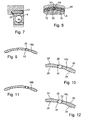
- FIGS. 7 and 8 engages a pin 28 which engages in a recess 30 of the housing ring 12, in addition to a slot 32, with which the radial wave springs 18 are formed.
- the pin 28 is held in this way in the circumferential direction immovably between the bearing outer ring 4 and the housing ring 12 so that it fixes the or the radial corrugated springs 18 in the circumferential direction.
- the waves or bumps of adjacent radial corrugated springs are offset in the circumferential direction to each other in order to achieve the most uniform loading of the bearing.
- different radial wave springs would have to be manufactured with different relative arrangement of slot and bumps or waves.
- Fig. 10 is located at the continuously drawn radial wave spring 18b left of the pin 28, a radially outward bearing cradle and right of the pin 28 a radially inwardly directed support hump. Further, to the left of the pin is a support hump 24 opposite, radially inwardly directed abutment bump and right of pin 28 a support cusp 24 opposite, radially outwardly directed abutment bump 26. In 180 ° twisted installation of the radial wave spring 18b results in the dashed line arrangement, that is a stop bump is a support cusp axially adjacent.
- FIGS. 13 and 14 show a feather key 36 which is inserted into a groove in the base body 8 and penetrates slots in the housing ring 12 and the radial field spring 18.
- FIG. 15 shows an embodiment in which the housing ring 12 is provided with a radial rib which engages in the slot 32 of the radial wave spring 18.
- the radial wave spring 18 is provided with a radially outwardly extending rib 40 which engages in a recess of the housing ring 12.
- the housing ring 12 is held immovably in the circumferential direction on the base body 8.
- each radial wave spring 18 c ends on one side of the slot 32 in an axially extending projection or pin 42.
- the pin 42 of the axially outermost radial wave spring engages in a recess 44 formed in a radial surface of the base body 8.
- the pins 42 of the axially adjacent respective radial corrugated springs engage in the slot 32 in accordance with FIG. 17 each right side adjacent radial wave spring.
- the radial wave spring rings can be inexpensively manufactured as stamped and bent parts.
- FIGS. 18 to 25 Be explained in the following further advantageous embodiments of devices with which the storage of the main body can be decoupled.
- the outer surface of the bearing outer ring 4 is provided with a wide circumferential groove 46, are arranged in the radial wave springs 18b.
- Radial Wave Springs For example, 18b may be similarly pre-assembled as retaining rings are mounted in shaft grooves. The remaining axially outside of the circumferential groove 46 shoulders of the bearing outer ring 4 (enlarged view X) can directly form a radial stop. Further, between side walls of the base body 8 and the ring cover 10 and the bearing outer ring O-rings 48 may be mounted for axial guidance.
- FIGS. 20 and 21 is different from that of FIGS. 18 and 19 merely in that in the outer surface of the bearing outer ring 4 a plurality of grooves 46 are formed, in each of which a single radial wave spring 18b is arranged.
- the bearing outer ring 4 is provided with two circumferential grooves 46, wherein in accordance with FIG. 22 left circumferential groove three radial wave springs 18c are arranged and in the axially open right circumferential groove 46 four radial corrugated springs 18c are arranged.
- the formed on the base body 8 opposite or inner surface 16 has a step 50 on which the left Axialwellfeder is supported.
- the axially outermost radial wave spring 18 c in the right circumferential groove 46 is supported on a radially extending side surface 52 of the annular cover 10.
- FIG. 23 shows the section X of the FIG. 22 in an enlarged view.
- the individual radial corrugated springs 18c are similar in terms of their radial extent with bumps, for example, according to embodiment FIG. 4 trained (see FIG. 24 ).
- the radial wave springs 18c are corrugated in the axial direction, as shown FIG. 25 apparent, the one Top view of a portion of the axially adjacent radial wave springs 18c shows.
- a decoupling or acoustic decoupling of the bearing is achieved by the body in the radial and axial directions.
- the formed between the circumferential grooves 46 nose 54 of the bearing outer ring 4 can be used as a stop.
- the number of grooves, the corrugation of the radial corrugated springs or their formation with bumps, the axial and radial guidance and stops can each in appropriate manner by changing the number of radial corrugated springs, the grooves, additional axial corrugation, the use of O-rings, etc .. . be formed.
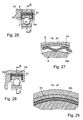
- FIGS. 26 and 27 show the arrangement of radial corrugated springs 18a between the bearing outer ring 4 and an attached to the bearing outer ring 4 annular sleeve 54 with a total U-shaped cross-section.
- the radial wave springs 18a are loosely seated on the bearing outer ring 4 and held axially by positioning rings 22 disposed between the outer radial wave springs and the radial side walls 56 of the sleeve 54.
- the sleeve can be produced inexpensively, for example, as sheet metal forming part and fulfilled by appropriately bent formation of the side walls 56 at the same time the function of an axial spring similar to a plate spring. In this way, the storage is according to FIGS. 26 and 27 axially and radially decoupled from the main body 8.
- FIGS. 28 and 29 is different from that of FIGS. 26 and 27 in that, instead of the radial corrugated springs 18a, radial corrugated springs 18b provided with bumps are used, and positioning rings 22 are arranged between the radial corrugated springs 18b.
- the bearing outer ring 4 is provided with two axially outwardly open circumferential grooves 46 in which axially and radially corrugated radial corrugated springs 18 c are arranged, which are enclosed by a sleeve ring 54.
- the sleeve 54 is bent twice in the transition from its bottom to the side walls 56, and serves for axially and radially biased support of the radial wave springs 18c.
- the sleeve itself has no function of an axial spring.
- the function of the axial spring or axial decoupling is taken over by the axially corrugated radial corrugated springs 18c.
- the sleeve 54 serves only as a stop. FIG.
- FIG. 31 shows the enlarged section X of the FIG. 30.
- FIG. 32 shows a side view of a radial wave spring 18c and
- FIG. 33 shows a plan view of a section of juxtaposed, and axially corrugated radial corrugated springs 18c.
- FIG. 34 encloses a cross-sectionally U-shaped annular spring sleeve 18d the bearing outer ring 4 in the axial and radial directions.
- the bottom of the spring sleeve 18d has a radial corrugation with axial wavelength direction such that an externally visible circumferential groove 58 results.
- FIG. 35 shows the section X of the FIG. 34 in an enlarged view. It is clearly visible how the outer surface 14 is also formed with a shallow recess, so that the axially formed outside the recess or the groove 58 game d between the inside of the spring sleeve 18 d and the outer surface 14 of the outer ring 4 is smaller than the radial corrugation Spring sleeve 18d. This clearance d is available for a radial displacement of the bearing and can be adjusted by appropriate depth of the recess and height of the corrugation.
- the embodiment is characterized according to FIGS. 34 and 35 by a particularly simple training with few parts. It is understood that the formation of the outer surface 14 of the outer ring 4 with a circumferential recess or groove is not mandatory. With the help of the flat groove in the outer surface 14 of the bearing outer ring 4 is achieved that the curvature of the spring sleeve 18 d can be selected independently of the radial clearance d.
- the side walls 62 of the spring sleeve 18 d in addition, for example, in the transition region to the bottom 60 outward be curved, so that the spring sleeve takes over the function of an axial spring and radial spring.
- the spring sleeve 18d according to FIG. 34 has a radial curvature or undulation with axial wave direction.
- the spring sleeve 18e according to the embodiment FIGS. 36 and 37 a radial corrugation with circumferentially extending wavelength, as shown FIG. 37 can be seen, which is a view in the direction of arrows II-II in FIG. 36 shows.
- the advantage is achieved that larger elastic compliances are achieved by larger possible wavelengths.
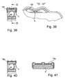
- the Figures 38 and 39 show a combination of the embodiments of the spring sleeve according to FIGS. 34 to 37 , wherein the spring sleeve 18d of the Figures 38 and 39 having a radial corrugation with axial and circumferentially extending wavelength direction.
- the spring sleeve 18d of the Figures 38 and 39 having a radial corrugation with axial and circumferentially extending wavelength direction.
- FIGS. 40 and 41 show an embodiment of a spring sleeve 18g, basically the of FIG. 34 corresponds, but has a plurality of radial bulges with axial wavelength direction, the height of which is different. This allows progressive characteristics to be achieved. With respect to an axial displacement of the bearing, the spring sleeve has 18g no resilient but merely stop action.
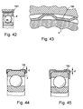
- FIGS. 42 and 43 shows a over the entire width of the outer ring 4 extending radial wave spring whose radial corrugation has a wavelength direction in the circumferential direction, the wave heights are different. This makes it possible to achieve more forgiving, progressive identifiers.
- radial wave spring 18h can be supplemented by side walls to form a spring sleeve. Further, not only the wave heights but also the wavelengths of the corrugations may be different.
- FIGS. 44 and 45 corresponds to the FIG. 34 , wherein the outer surface of the bearing outer ring 4 is formed without a recess or groove, so that the wave height of the spring ring 18i is equal to the possible radial displacement of the bearing.
- the side walls of the spring ring 18i extend parallel to the side walls of the bearing outer ring 4, so that the spring sleeve 18i has no function of an axial spring.
- the spring sleeve 18d of FIG. 45 corresponds to the FIG. 34 , that is, the spring sleeve 18d additionally has the function of an axial spring.
- FIG. 46 represents in the left half of the figure in longitudinal section and in the right half of the figure in side view another embodiment of a spring sleeve designed as a radial spring.
- the bearing outer ring 4 is surrounded by a thin-walled spring steel sheet existing spring sleeve 18j, the is generally U-shaped in cross-section and its radial side walls 66 are radially supported on an annular step 68 which is formed on the side surface of the outer ring 4.
- a radial compliance is achieved by a crown or radial bulge of the bottom 70 of the spring sleeve 18j.
- the basic stiffness can be influenced by the sheet thickness.
- the spring characteristic can be suitably selected by selecting the curvature profile of the floor, optionally multiple corrugated, and / or the contour of the side walls 66.
- the spring characteristic can be influenced by the fact that the bottom 70 touches the outer surface of the outer ring 4 after a certain radial deformation.
- an axial compliance of the spring sleeve 18k can be influenced by appropriate design of the side walls 66 and the adjacent side surfaces of the bearing outer ring 4. By asymmetrical bending in its plane, the radial side walls 66 can additionally contribute to the radial compliance of the spring sleeve 18j.
- Increased compliance in the circumferential direction can be achieved by radial slots 72 penetrating the bottom 70 and partially the sidewalls 66 of the spring sleeve 18k. Due to the interruption of the membrane stresses in the lateral surface or in the bottom of the spring sleeve 18k and their radial compliance is increased.
- the spring sleeve 18j does not have to extend integrally around the entire circumference of the outer ring 4. It can be designed in the form of two circumferential segments. A cohesion of the spring sleeve is ensured in the installed state by the receiving bore or recess of the base body 8, which is facilitated by the crown of the spring sleeve assembly.
- a circumferential radial projection 74 of the spring sleeve 18j can be used, which engages in an annular groove 76 on the base body 8.
- the annular groove 76 may be formed by a formed on the inner surface 16 of the base body 8 gradation, which is laterally closed by the attached to the base 8 ring cover 10. It is understood that at low forces to be absorbed, the spring sleeve 18k may be radially formed so resilient that they can be pressed laterally together with the bearing inner ring 2 and the bearing outer ring 4 and the interposed rolling elements 6 in the body, so that the annular groove 76 in the inner surface 16 may be pierced.
- FIG. 47 is different from that of FIG. 46 primarily by the fact that the axial fixation of the spring sleeve 18k is effected by annular surfaces 78 of Einlegeingen 78, via which the spring sleeve 18k is supported on a radial side surface of the base body 8 and the correspondingly formed annular cover 10.
- the Einlegeringe can for example Plastic exist. An axial constraint of the spring sleeve 18k due to a radial displacement can be avoided if necessary by axial play, but this can be very small.
- Figures 48 to 50 illustrate embodiments of the decoupling device that works with radial wave spring segments, the bearing outer ring, not shown 4 ( FIG. 1 ) do not completely enclose, but only along a peripheral region, for example, of about 180 ° and which are arranged on the loaded side of the bearing outer ring.
- FIG. 48 shows a side view of a radial wave spring segment 181, which extends over more than half a circumference and is formed with respect to its corrugation similar to, for example, the radial wave spring 18b according to FIG. 4 .
- a plurality of radial wave spring segments 18I are arranged axially adjacent to each other, as in FIG. 49 shown.
- a positioning member 82 which is formed as a sleeve segment such that it completely encloses the bearing outer ring 4 together with the radial wave spring segments 181.
- the positioning member 82 on axial lugs 84 which engage in recesses which on the main body 8 are formed.
- the positioning member 62 formed such that all radial wave spring segments 18I are arranged axially without offset side by side.
- the positioning member 82 is provided at its side edges with recesses and projections, so that adjacent radial wave spring segments 18I are each arranged offset in the circumferential direction. This is advantageous for the in FIG. 48 visible support bumps 24 and bumps 26 (for more details see FIG. 4 ) are arranged, for example, on a gap.
- An advantage associated with the embodiments according to Figures 48 to 50 is achieved, is that the utilization of, for example, complex blanking plate for the radial wave springs with respect to the formation of radial corrugated springs, which extend over the entire circumference (possibly with slot), is significantly improved.
Landscapes
- General Engineering & Computer Science (AREA)
- Engineering & Computer Science (AREA)
- Mechanical Engineering (AREA)
- Support Of The Bearing (AREA)
- Springs (AREA)
- Replacement Of Web Rolls (AREA)
- Mounting Of Bearings Or Others (AREA)
- Constituent Portions Of Griding Lathes, Driving, Sensing And Control (AREA)
- Soil Working Implements (AREA)
- Transmissions By Endless Flexible Members (AREA)
- Vibration Prevention Devices (AREA)
- Golf Clubs (AREA)
- Centrifugal Separators (AREA)
- Pulleys (AREA)
- Sliding-Contact Bearings (AREA)
Applications Claiming Priority (2)
| Application Number | Priority Date | Filing Date | Title |
|---|---|---|---|
| DE10208995 | 2002-02-28 | ||
| EP03722195A EP1481174B1 (fr) | 2002-02-28 | 2003-02-25 | Dispositif de desaccouplement d un roulement d un arbre , situe sur un corps de base, et ressort ondule radial |
Related Parent Applications (2)
| Application Number | Title | Priority Date | Filing Date |
|---|---|---|---|
| EP03722195.9 Division | 2003-02-25 | ||
| EP03722195A Division EP1481174B1 (fr) | 2002-02-28 | 2003-02-25 | Dispositif de desaccouplement d un roulement d un arbre , situe sur un corps de base, et ressort ondule radial |
Publications (3)
| Publication Number | Publication Date |
|---|---|
| EP1908972A2 true EP1908972A2 (fr) | 2008-04-09 |
| EP1908972A3 EP1908972A3 (fr) | 2010-08-18 |
| EP1908972B1 EP1908972B1 (fr) | 2011-11-02 |
Family
ID=27740559
Family Applications (2)
| Application Number | Title | Priority Date | Filing Date |
|---|---|---|---|
| EP08000885A Expired - Lifetime EP1908972B1 (fr) | 2002-02-28 | 2003-02-25 | Dispositif de désaccouplement d'un roulement d'un arbre situé sur un corps de base, et ressort ondulé radial |
| EP03722195A Expired - Lifetime EP1481174B1 (fr) | 2002-02-28 | 2003-02-25 | Dispositif de desaccouplement d un roulement d un arbre , situe sur un corps de base, et ressort ondule radial |
Family Applications After (1)
| Application Number | Title | Priority Date | Filing Date |
|---|---|---|---|
| EP03722195A Expired - Lifetime EP1481174B1 (fr) | 2002-02-28 | 2003-02-25 | Dispositif de desaccouplement d un roulement d un arbre , situe sur un corps de base, et ressort ondule radial |
Country Status (10)
| Country | Link |
|---|---|
| US (2) | US7478952B2 (fr) |
| EP (2) | EP1908972B1 (fr) |
| JP (1) | JP4431395B2 (fr) |
| KR (1) | KR20040094742A (fr) |
| CN (1) | CN1327144C (fr) |
| AT (2) | ATE410610T1 (fr) |
| AU (1) | AU2003229478A1 (fr) |
| DE (3) | DE10307842A1 (fr) |
| NL (1) | NL1022788C2 (fr) |
| WO (1) | WO2003072969A2 (fr) |
Cited By (3)
| Publication number | Priority date | Publication date | Assignee | Title |
|---|---|---|---|---|
| DE102011012913A1 (de) | 2010-03-22 | 2011-09-22 | Schaeffler Technologies Gmbh & Co. Kg | Lagerelement |
| US10400817B2 (en) | 2016-11-22 | 2019-09-03 | Woodward, Inc. | Radial bearing device |
| CN110337532A (zh) * | 2017-02-28 | 2019-10-15 | 赛峰飞机发动机公司 | 包括在两个同心轴之间的轴承的飞行器发动机 |
Families Citing this family (56)
| Publication number | Priority date | Publication date | Assignee | Title |
|---|---|---|---|---|
| JP4806827B2 (ja) * | 2003-04-07 | 2011-11-02 | シェフラー テクノロジーズ ゲゼルシャフト ミット ベシュレンクテル ハフツング ウント コンパニー コマンディートゲゼルシャフト | 円錐形ディスク式巻掛け伝動装置および突起付きリング |
| DE102004006888A1 (de) * | 2004-02-12 | 2005-09-01 | Hilti Ag | Absaugvorrichtung |
| FR2880661B1 (fr) * | 2005-01-10 | 2008-08-08 | Timken France Soc Par Actions | Module de roulement |
| DE102006012598B4 (de) * | 2006-03-18 | 2010-10-07 | Zf Lenksysteme Gmbh | Wälzlager |
| ES2385025T3 (es) | 2006-09-07 | 2012-07-17 | Saint-Gobain Performance Plastics Rencol Limited | Anillo de montaje de combinación |
| US7589447B2 (en) * | 2006-12-05 | 2009-09-15 | Honeywell International Inc. | High speed aerospace generator resilient mount |
| EP2087984B1 (fr) * | 2008-02-05 | 2010-05-12 | Texmag GmbH Vertriebsgesellschaft | Cylindre destiné à exercer une pression de contact sur des bandes de matériau |
| DE102008013131B4 (de) * | 2008-03-07 | 2015-12-31 | Ab Skf | Lageranordnung für eine Tragrolle |
| JP5167514B2 (ja) * | 2008-05-29 | 2013-03-21 | Ntn株式会社 | 転がり軸受アセンブリ |
| KR20100116688A (ko) * | 2008-10-27 | 2010-11-01 | 코요 베어링즈 유에스에이, 엘엘씨 | 크랭크샤프트용 소음 차단 롤링 요소 베어링 |
| US8851227B2 (en) * | 2009-01-23 | 2014-10-07 | Aktiebolaget Skf | Bearing assembly for a power steering mechanism |
| US8337090B2 (en) * | 2009-09-10 | 2012-12-25 | Pratt & Whitney Canada Corp. | Bearing support flexible ring |
| CN102079329B (zh) * | 2009-11-30 | 2013-05-29 | 万都株式会社 | 齿型辅助之电动转向装置 |
| DE102009056352B4 (de) | 2009-11-30 | 2015-06-18 | Schaeffler Technologies AG & Co. KG | Wälzlager mit am Lageraußenring angebrachten höckerartigen Vorsprüngen |
| DE102010015709A1 (de) | 2010-04-21 | 2011-10-27 | Schaeffler Technologies Gmbh & Co. Kg | Akustische Entkopplungsvorrichtung für ein Lager und Lager mit einer solchen Entkopplungsvorrichtung |
| PL2412528T3 (pl) * | 2010-07-28 | 2015-05-29 | Boettcher Gmbh & Co Felix | Sposób naprawy walca |
| DE102010054937A1 (de) * | 2010-12-17 | 2012-06-21 | Schaeffler Technologies Gmbh & Co. Kg | Lageranordnung für einen Turbolader |
| DE102011005761A1 (de) * | 2011-03-18 | 2012-09-20 | Schaeffler Technologies Gmbh & Co. Kg | Lageranordnung mit einem Fanglager |
| WO2013009898A1 (fr) | 2011-07-11 | 2013-01-17 | Paper Software LLC | Système et procédé de traitement de document |
| CA2870683C (fr) * | 2012-04-25 | 2017-03-28 | General Electric Company | Appareil et procede pour assembler un ensemble palier d'amortisseur |
| DE102012209459A1 (de) | 2012-06-05 | 2013-12-05 | Schaeffler Technologies AG & Co. KG | Geclipster Stahlreifen eines CVT-Lagers |
| DE102013211461A1 (de) | 2012-06-22 | 2013-12-24 | Schaeffler Technologies AG & Co. KG | Akustische Isolierung an einem Lager und akustisches Lagerabkoppelungselement |
| GB2518102A (en) * | 2012-06-28 | 2015-03-11 | Skf Ab | Machine arrangement |
| DE102012216447A1 (de) | 2012-09-14 | 2014-05-15 | Schaeffler Technologies Gmbh & Co. Kg | Beschichtungssystem für ein akustisch gedämpftes Lager und Wälzlager mit schwingungsdämpfendem Abkoppelungselement |
| DE102012221066A1 (de) * | 2012-11-19 | 2014-05-22 | Schaeffler Technologies Gmbh & Co. Kg | Lageranordnung zur Lagerung eines Wellenabschnitts, insbesondere bei einem Innenläufermotor |
| DE102012222802A1 (de) | 2012-12-11 | 2014-06-12 | Schaeffler Technologies Gmbh & Co. Kg | Wälzlageranordnung mit einer Vielzahl von metallischen Federbügeln |
| WO2014150356A1 (fr) | 2013-03-15 | 2014-09-25 | King Cycle Group, Inc. | Ensemble cylindre utilisant une cale |
| DE102013213172A1 (de) * | 2013-07-04 | 2015-01-08 | Bosch Mahle Turbo Systems Gmbh & Co. Kg | Abgasturbolader |
| DE102013215837A1 (de) * | 2013-08-12 | 2015-02-12 | Schaeffler Technologies Gmbh & Co. Kg | Wälzlager |
| JP2015068307A (ja) * | 2013-09-30 | 2015-04-13 | 三浦工業株式会社 | スクロール流体機械 |
| DE102013226527A1 (de) * | 2013-12-18 | 2015-06-18 | Zf Friedrichshafen Ag | Kombinierte Wälz- und Gleitlagerung einer Getriebewelle |
| US20150252841A1 (en) * | 2014-03-05 | 2015-09-10 | Schaeffler Technologies AG & Co. KG | Bearing assembly with integrated spring |
| JP6481260B2 (ja) * | 2014-04-14 | 2019-03-13 | 日本精工株式会社 | 転がり軸受 |
| DE102014213880B4 (de) * | 2014-07-16 | 2016-04-07 | Aktiebolaget Skf | Lagerring eines Lagers, insbesondere eines Wälzlagers |
| DE102014220068A1 (de) | 2014-10-02 | 2016-04-07 | Schaeffler Technologies AG & Co. KG | Lagerung zur akustischen Entkopplung |
| WO2016112887A1 (fr) * | 2015-01-14 | 2016-07-21 | Schaeffler Technologies AG & Co. KG | Palier découplé du bruit pour transmission cvt à rainure ovale |
| DE102015207156A1 (de) | 2015-04-20 | 2016-10-20 | Schaeffler Technologies AG & Co. KG | Doppelkupplungsgetriebe |
| JP6513501B2 (ja) | 2015-06-15 | 2019-05-15 | 大豊工業株式会社 | ワッシャの製造方法及びワッシャ |
| EP3255289B1 (fr) * | 2016-06-09 | 2020-12-09 | Claverham Limited | Fente de délestage pour un ensemble de support de charge |
| DE102016211714B3 (de) * | 2016-06-29 | 2017-09-07 | Ford Global Technologies, Llc | Getriebeeinheit für ein Kraftfahrzeug |
| DE102016211741A1 (de) * | 2016-06-29 | 2018-01-04 | Schaeffler Technologies AG & Co. KG | Wälzlager und Gehäuse für ein Getriebe |
| KR101854984B1 (ko) * | 2016-07-05 | 2018-05-04 | 주식회사 만도 | 랙구동형 동력 보조 조향장치 |
| US10228051B2 (en) * | 2016-07-22 | 2019-03-12 | Ford Global Technologies, Llc | Two-piece molded pulley having radial bearing distortion-reducing characteristics |
| DE102016214505A1 (de) | 2016-08-05 | 2018-02-08 | Robert Bosch Gmbh | Ausgleichshülse für eine Lagereinrichtung, Lagereinrichtung mit einer Ausgleichshülse und Verfahren zum Montieren einer Ausgleichshülse |
| US10247237B2 (en) * | 2016-09-09 | 2019-04-02 | Lg Electronics Inc. | Rolling bearing and motor having the same |
| CN106352016A (zh) * | 2016-11-16 | 2017-01-25 | 沈阳航空航天大学 | 一种外圈或轴颈带凸台的增阻式挤压油膜阻尼器 |
| CN106402270A (zh) * | 2016-11-16 | 2017-02-15 | 沈阳航空航天大学 | 一种外圈带凹槽及轴颈带凸台的增阻式挤压油膜阻尼器 |
| EP3625468B1 (fr) | 2017-05-18 | 2024-04-03 | GKN Automotive Limited | Rondelle d'engrenage différentiel profilée avec trajet d'écoulement de fluide défini |
| JP6961507B2 (ja) * | 2018-02-01 | 2021-11-05 | 本田技研工業株式会社 | 軸受装置 |
| DE102018102270B4 (de) * | 2018-02-01 | 2021-06-10 | Dr. Ing. H.C. F. Porsche Aktiengesellschaft | Lagerscheibe für ein Fahrzeuglager eines Fahrzeugs |
| US10495144B1 (en) * | 2018-05-25 | 2019-12-03 | Borgwarner Inc. | Single-row ball bearing with integrated squeeze-film damper |
| JP7281422B2 (ja) * | 2020-01-15 | 2023-05-25 | 株式会社シマノ | 釣り用リール |
| US11137032B1 (en) * | 2020-05-29 | 2021-10-05 | Bell Textron Inc. | Ceramic bearing system |
| FR3135655B1 (fr) * | 2022-05-20 | 2026-01-16 | Psa Automobiles Sa | Dispositif de verrouillage du type circlip pour le montage de roulements sur des VÉHICULES AUTOMOBILES |
| US11971079B2 (en) * | 2022-07-11 | 2024-04-30 | GM Global Technology Operations LLC | Dual deflection ring vibration reduction system |
| CN116608391A (zh) * | 2023-04-12 | 2023-08-18 | 中国能源建设集团广东电力工程局有限公司 | 一种厚度可调的垫圈 |
Family Cites Families (22)
| Publication number | Priority date | Publication date | Assignee | Title |
|---|---|---|---|---|
| US1386255A (en) * | 1919-04-29 | 1921-08-02 | John George William Gruban | Roller, ball, and other bearing |
| US1423950A (en) * | 1919-11-03 | 1922-07-25 | Nordiska Kullager Ab | Antifriction ball or roller bearing |
| CH361692A (de) | 1957-06-24 | 1962-04-30 | Gen Motors Corp | Gasturbinentriebwerk |
| US3372963A (en) * | 1965-12-02 | 1968-03-12 | Rotron Mfg Co | Corrugated bearing ring |
| GB1247494A (en) * | 1967-11-29 | 1971-09-22 | Molins Machine Co Ltd | Improvements in or relating to tolerance rings |
| GB1246263A (en) * | 1967-11-29 | 1971-09-15 | Anthony Raphael Gaster | Improvements in or relating to tolerance rings |
| FR2271443B2 (fr) * | 1974-01-23 | 1977-06-10 | Pitner Alfred | |
| DD218655A1 (de) * | 1983-05-02 | 1985-02-13 | Elektrogeraete Ingbuero Veb | Elastisches element zum toleranzausgleichenden einbau von lagern |
| US4981390A (en) * | 1987-03-06 | 1991-01-01 | The Ray Engineering Co., Ltd. | Tolerance ring with retaining means |
| DE3738039A1 (de) | 1987-11-09 | 1989-05-18 | Thieme Werner Gmbh & Co | Siebdruckmaschine |
| US5062721A (en) * | 1989-04-28 | 1991-11-05 | Nippon Seiko Kabushiki Kaisha | Rolling bearing with sleeve |
| US5044789A (en) * | 1990-04-16 | 1991-09-03 | Eaton Corporation | Roller and ball bearing bearing isolator |
| US5584582A (en) * | 1994-12-15 | 1996-12-17 | Air Products And Chemicals, Inc. | Bump foil design for improved damping and load capacity from compliant foil gas bearings |
| DE29500585U1 (de) | 1995-01-16 | 1995-03-02 | INA Wälzlager Schaeffler KG, 91074 Herzogenaurach | Distanzring |
| GB9518018D0 (en) * | 1995-09-05 | 1995-11-08 | Lilleshall Plastics Eng | Tolerence rings |
| US5902049A (en) * | 1997-03-28 | 1999-05-11 | Mohawk Innovative Technology, Inc. | High load capacity compliant foil hydrodynamic journal bearing |
| US6123462A (en) * | 1998-09-28 | 2000-09-26 | General Electric Company | Bearing system having reduced noise and axial preload |
| DE19958073B4 (de) * | 1998-12-16 | 2012-04-26 | Schaeffler Technologies Gmbh & Co. Kg | Kegelscheibenumschlingungsgetriebe |
| JP3536022B2 (ja) * | 2000-10-04 | 2004-06-07 | ミネベア株式会社 | ピボット軸受装置 |
| DE10195939D2 (de) * | 2001-02-01 | 2004-01-15 | Luk Lamellen & Kupplungsbau | Lageranordnung |
| US6939052B1 (en) * | 2003-01-27 | 2005-09-06 | Precision Components, Inc. | Bearing with integrated mounting features |
| US7052183B2 (en) * | 2004-06-15 | 2006-05-30 | Honeywell International Inc. | Composite resilient mount |
-
2003
- 2003-02-25 WO PCT/DE2003/000576 patent/WO2003072969A2/fr not_active Ceased
- 2003-02-25 CN CNB038048825A patent/CN1327144C/zh not_active Expired - Fee Related
- 2003-02-25 AT AT03722195T patent/ATE410610T1/de not_active IP Right Cessation
- 2003-02-25 US US10/505,924 patent/US7478952B2/en not_active Expired - Fee Related
- 2003-02-25 AU AU2003229478A patent/AU2003229478A1/en not_active Abandoned
- 2003-02-25 JP JP2003571623A patent/JP4431395B2/ja not_active Expired - Fee Related
- 2003-02-25 DE DE10307842A patent/DE10307842A1/de not_active Withdrawn
- 2003-02-25 KR KR10-2004-7013366A patent/KR20040094742A/ko not_active Ceased
- 2003-02-25 AT AT08000885T patent/ATE531961T1/de active
- 2003-02-25 EP EP08000885A patent/EP1908972B1/fr not_active Expired - Lifetime
- 2003-02-25 EP EP03722195A patent/EP1481174B1/fr not_active Expired - Lifetime
- 2003-02-25 DE DE2003190781 patent/DE10390781D2/de not_active Expired - Fee Related
- 2003-02-25 DE DE50310608T patent/DE50310608D1/de not_active Expired - Lifetime
- 2003-02-26 NL NL1022788A patent/NL1022788C2/nl not_active IP Right Cessation
-
2008
- 2008-12-11 US US12/316,319 patent/US7927020B2/en not_active Expired - Fee Related
Cited By (4)
| Publication number | Priority date | Publication date | Assignee | Title |
|---|---|---|---|---|
| DE102011012913A1 (de) | 2010-03-22 | 2011-09-22 | Schaeffler Technologies Gmbh & Co. Kg | Lagerelement |
| WO2011116739A1 (fr) | 2010-03-22 | 2011-09-29 | Schaeffler Technologies Gmbh & Co. Kg | Élément d'amortissement de palier |
| US10400817B2 (en) | 2016-11-22 | 2019-09-03 | Woodward, Inc. | Radial bearing device |
| CN110337532A (zh) * | 2017-02-28 | 2019-10-15 | 赛峰飞机发动机公司 | 包括在两个同心轴之间的轴承的飞行器发动机 |
Also Published As
| Publication number | Publication date |
|---|---|
| US7927020B2 (en) | 2011-04-19 |
| WO2003072969A2 (fr) | 2003-09-04 |
| ATE531961T1 (de) | 2011-11-15 |
| EP1481174A2 (fr) | 2004-12-01 |
| KR20040094742A (ko) | 2004-11-10 |
| CN1327144C (zh) | 2007-07-18 |
| AU2003229478A8 (en) | 2003-09-09 |
| US20090103846A1 (en) | 2009-04-23 |
| DE10390781D2 (de) | 2005-01-13 |
| EP1908972B1 (fr) | 2011-11-02 |
| US7478952B2 (en) | 2009-01-20 |
| NL1022788A1 (nl) | 2003-08-29 |
| US20050232525A1 (en) | 2005-10-20 |
| NL1022788C2 (nl) | 2003-11-04 |
| DE50310608D1 (de) | 2008-11-20 |
| AU2003229478A1 (en) | 2003-09-09 |
| CN1639478A (zh) | 2005-07-13 |
| WO2003072969A3 (fr) | 2003-11-06 |
| JP2005519238A (ja) | 2005-06-30 |
| EP1908972A3 (fr) | 2010-08-18 |
| EP1481174B1 (fr) | 2008-10-08 |
| ATE410610T1 (de) | 2008-10-15 |
| DE10307842A1 (de) | 2003-09-11 |
| JP4431395B2 (ja) | 2010-03-10 |
Similar Documents
| Publication | Publication Date | Title |
|---|---|---|
| EP1908972B1 (fr) | Dispositif de désaccouplement d'un roulement d'un arbre situé sur un corps de base, et ressort ondulé radial | |
| DE3206068C2 (de) | Kupplungsscheibe | |
| DE10203307A1 (de) | Lageranordnung | |
| EP2446166B1 (fr) | Rondelle ondulée et ensemble de support pour arbre | |
| DE102013110396A1 (de) | Zahnradanordnung | |
| DE3205039A1 (de) | Kupplungsscheibe | |
| WO2017041802A1 (fr) | Engrenage à roue dentée élastique | |
| DE2823894C2 (de) | Drehschwingungsdämpfer | |
| WO2015043587A1 (fr) | Dispositif pendulaire centrifuge | |
| DE102019105760A1 (de) | Wellgetriebe und Verfahren zur Herstellung eines elastischen Getriebebauteils | |
| DE102014111383A1 (de) | Nockenwelle mit Schiebenockenpaket | |
| DE3049670T1 (de) | Zweistufiger koaxialer federdaempfer | |
| EP3050194B1 (fr) | Module équipé d'une machine électrique | |
| WO2007039384A1 (fr) | Poussoir a galet | |
| DE102012103886A1 (de) | Aktor | |
| DE19629497B4 (de) | Scheibenanordnung mit Dämpfer | |
| EP0025901A2 (fr) | Accouplement élastique | |
| EP3828442A1 (fr) | Roue dentée souple et boîte de vitesses dotée d'une telle roue dentée souple | |
| DE102004015215A1 (de) | Entkoppelungsvorrichtung für eine Lagerung einer Welle an einem Grundkörper sowie Radialwellfeder | |
| DE10007991A1 (de) | Getriebe | |
| DE102014211272A1 (de) | Wellenkupplung | |
| DE10223815B4 (de) | Kopplungsvorrichtung zur Kopplung eines Kraftfahrzeugmotors mit einem Getriebe | |
| EP2302255B1 (fr) | Dispositif d'entraînement pour au moins un engrenage auxiliaire | |
| DE102023122917A1 (de) | Aktuatoranordnung für eine Reiblamellenkupplung und Differentialanordnung mit einer solchen Aktuatoranordnung | |
| DE102015222644A1 (de) | Geräuschentkoppeltes Lager für ein CVT-Getriebe mit ovaler Nut |
Legal Events
| Date | Code | Title | Description |
|---|---|---|---|
| PUAI | Public reference made under article 153(3) epc to a published international application that has entered the european phase |
Free format text: ORIGINAL CODE: 0009012 |
|
| AC | Divisional application: reference to earlier application |
Ref document number: 1481174 Country of ref document: EP Kind code of ref document: P |
|
| AK | Designated contracting states |
Kind code of ref document: A2 Designated state(s): AT BE BG CH CY CZ DE DK EE ES FI FR GB GR HU IE IT LI LU MC NL PT SE SI SK TR |
|
| RIN1 | Information on inventor provided before grant (corrected) |
Inventor name: LINNENBRUEGGER, ANDRE, DR. Inventor name: WODTKE, HANS-WALTER, DR. Inventor name: FAUST, HARTMUT, DR.-ING. Inventor name: GLAS, RONALD Inventor name: BAUER, CHRISTIAN Inventor name: FRIEDMANN, OSWALD |
|
| PUAL | Search report despatched |
Free format text: ORIGINAL CODE: 0009013 |
|
| AK | Designated contracting states |
Kind code of ref document: A3 Designated state(s): AT BE BG CH CY CZ DE DK EE ES FI FR GB GR HU IE IT LI LU MC NL PT SE SI SK TR |
|
| 17P | Request for examination filed |
Effective date: 20110218 |
|
| AKX | Designation fees paid |
Designated state(s): AT BE BG CH CY CZ DE DK EE ES FI FR GB GR HU IE IT LI LU MC NL PT SE SI SK TR |
|
| RAP1 | Party data changed (applicant data changed or rights of an application transferred) |
Owner name: SCHAEFFLER TECHNOLOGIES GMBH & CO. KG |
|
| GRAP | Despatch of communication of intention to grant a patent |
Free format text: ORIGINAL CODE: EPIDOSNIGR1 |
|
| RIC1 | Information provided on ipc code assigned before grant |
Ipc: F16C 25/08 20060101ALI20110513BHEP Ipc: F16C 35/077 20060101AFI20110513BHEP |
|
| GRAS | Grant fee paid |
Free format text: ORIGINAL CODE: EPIDOSNIGR3 |
|
| GRAA | (expected) grant |
Free format text: ORIGINAL CODE: 0009210 |
|
| AC | Divisional application: reference to earlier application |
Ref document number: 1481174 Country of ref document: EP Kind code of ref document: P |
|
| AK | Designated contracting states |
Kind code of ref document: B1 Designated state(s): AT BE BG CH CY CZ DE DK EE ES FI FR GB GR HU IE IT LI LU MC NL PT SE SI SK TR |
|
| REG | Reference to a national code |
Ref country code: GB Ref legal event code: FG4D Free format text: NOT ENGLISH |
|
| REG | Reference to a national code |
Ref country code: CH Ref legal event code: EP |
|
| REG | Reference to a national code |
Ref country code: IE Ref legal event code: FG4D |
|
| REG | Reference to a national code |
Ref country code: DE Ref legal event code: R096 Ref document number: 50314053 Country of ref document: DE Effective date: 20111229 |
|
| REG | Reference to a national code |
Ref country code: NL Ref legal event code: VDEP Effective date: 20111102 |
|
| RAP2 | Party data changed (patent owner data changed or rights of a patent transferred) |
Owner name: SCHAEFFLER TECHNOLOGIES AG & CO. KG |
|
| REG | Reference to a national code |
Ref country code: CH Ref legal event code: PFA Owner name: SCHAEFFLER TECHNOLOGIES AG & CO. KG Free format text: SCHAEFFLER TECHNOLOGIES GMBH & CO. KG#INDUSTRIESTRASSE 1-3#91074 HERZOGENAURACH (DE) -TRANSFER TO- SCHAEFFLER TECHNOLOGIES AG & CO. KG#INDUSTRIESTRASSE 1-3#91074 HERZOGENAURACH (DE) |
|
| PG25 | Lapsed in a contracting state [announced via postgrant information from national office to epo] |
Ref country code: NL Free format text: LAPSE BECAUSE OF FAILURE TO SUBMIT A TRANSLATION OF THE DESCRIPTION OR TO PAY THE FEE WITHIN THE PRESCRIBED TIME-LIMIT Effective date: 20111102 Ref country code: SE Free format text: LAPSE BECAUSE OF FAILURE TO SUBMIT A TRANSLATION OF THE DESCRIPTION OR TO PAY THE FEE WITHIN THE PRESCRIBED TIME-LIMIT Effective date: 20111102 Ref country code: PT Free format text: LAPSE BECAUSE OF FAILURE TO SUBMIT A TRANSLATION OF THE DESCRIPTION OR TO PAY THE FEE WITHIN THE PRESCRIBED TIME-LIMIT Effective date: 20120302 Ref country code: GR Free format text: LAPSE BECAUSE OF FAILURE TO SUBMIT A TRANSLATION OF THE DESCRIPTION OR TO PAY THE FEE WITHIN THE PRESCRIBED TIME-LIMIT Effective date: 20120203 Ref country code: SI Free format text: LAPSE BECAUSE OF FAILURE TO SUBMIT A TRANSLATION OF THE DESCRIPTION OR TO PAY THE FEE WITHIN THE PRESCRIBED TIME-LIMIT Effective date: 20111102 |
|
| REG | Reference to a national code |
Ref country code: IE Ref legal event code: FD4D |
|
| PG25 | Lapsed in a contracting state [announced via postgrant information from national office to epo] |
Ref country code: CY Free format text: LAPSE BECAUSE OF FAILURE TO SUBMIT A TRANSLATION OF THE DESCRIPTION OR TO PAY THE FEE WITHIN THE PRESCRIBED TIME-LIMIT Effective date: 20111102 |
|
| PG25 | Lapsed in a contracting state [announced via postgrant information from national office to epo] |
Ref country code: EE Free format text: LAPSE BECAUSE OF FAILURE TO SUBMIT A TRANSLATION OF THE DESCRIPTION OR TO PAY THE FEE WITHIN THE PRESCRIBED TIME-LIMIT Effective date: 20111102 Ref country code: SK Free format text: LAPSE BECAUSE OF FAILURE TO SUBMIT A TRANSLATION OF THE DESCRIPTION OR TO PAY THE FEE WITHIN THE PRESCRIBED TIME-LIMIT Effective date: 20111102 Ref country code: DK Free format text: LAPSE BECAUSE OF FAILURE TO SUBMIT A TRANSLATION OF THE DESCRIPTION OR TO PAY THE FEE WITHIN THE PRESCRIBED TIME-LIMIT Effective date: 20111102 Ref country code: BG Free format text: LAPSE BECAUSE OF FAILURE TO SUBMIT A TRANSLATION OF THE DESCRIPTION OR TO PAY THE FEE WITHIN THE PRESCRIBED TIME-LIMIT Effective date: 20120202 Ref country code: CZ Free format text: LAPSE BECAUSE OF FAILURE TO SUBMIT A TRANSLATION OF THE DESCRIPTION OR TO PAY THE FEE WITHIN THE PRESCRIBED TIME-LIMIT Effective date: 20111102 Ref country code: IE Free format text: LAPSE BECAUSE OF FAILURE TO SUBMIT A TRANSLATION OF THE DESCRIPTION OR TO PAY THE FEE WITHIN THE PRESCRIBED TIME-LIMIT Effective date: 20111102 |
|
| REG | Reference to a national code |
Ref country code: DE Ref legal event code: R097 Ref document number: 50314053 Country of ref document: DE |
|
| BERE | Be: lapsed |
Owner name: SCHAEFFLER TECHNOLOGIES G.M.B.H. & CO. KG Effective date: 20120228 |
|
| PG25 | Lapsed in a contracting state [announced via postgrant information from national office to epo] |
Ref country code: IT Free format text: LAPSE BECAUSE OF FAILURE TO SUBMIT A TRANSLATION OF THE DESCRIPTION OR TO PAY THE FEE WITHIN THE PRESCRIBED TIME-LIMIT Effective date: 20111102 |
|
| PLBE | No opposition filed within time limit |
Free format text: ORIGINAL CODE: 0009261 |
|
| STAA | Information on the status of an ep patent application or granted ep patent |
Free format text: STATUS: NO OPPOSITION FILED WITHIN TIME LIMIT |
|
| PG25 | Lapsed in a contracting state [announced via postgrant information from national office to epo] |
Ref country code: MC Free format text: LAPSE BECAUSE OF NON-PAYMENT OF DUE FEES Effective date: 20120229 |
|
| REG | Reference to a national code |
Ref country code: CH Ref legal event code: PL |
|
| 26N | No opposition filed |
Effective date: 20120803 |
|
| REG | Reference to a national code |
Ref country code: DE Ref legal event code: R081 Ref document number: 50314053 Country of ref document: DE Owner name: SCHAEFFLER TECHNOLOGIES AG & CO. KG, DE Free format text: FORMER OWNER: SCHAEFFLER TECHNOLOGIES GMBH & CO. KG, 91074 HERZOGENAURACH, DE Effective date: 20120828 Ref country code: DE Ref legal event code: R081 Ref document number: 50314053 Country of ref document: DE Owner name: SCHAEFFLER TECHNOLOGIES GMBH & CO. KG, DE Free format text: FORMER OWNER: SCHAEFFLER TECHNOLOGIES GMBH & CO. KG, 91074 HERZOGENAURACH, DE Effective date: 20120828 |
|
| GBPC | Gb: european patent ceased through non-payment of renewal fee |
Effective date: 20120225 |
|
| PG25 | Lapsed in a contracting state [announced via postgrant information from national office to epo] |
Ref country code: LI Free format text: LAPSE BECAUSE OF NON-PAYMENT OF DUE FEES Effective date: 20120229 Ref country code: CH Free format text: LAPSE BECAUSE OF NON-PAYMENT OF DUE FEES Effective date: 20120229 |
|
| REG | Reference to a national code |
Ref country code: DE Ref legal event code: R097 Ref document number: 50314053 Country of ref document: DE Effective date: 20120803 |
|
| PG25 | Lapsed in a contracting state [announced via postgrant information from national office to epo] |
Ref country code: BE Free format text: LAPSE BECAUSE OF NON-PAYMENT OF DUE FEES Effective date: 20120228 |
|
| PG25 | Lapsed in a contracting state [announced via postgrant information from national office to epo] |
Ref country code: GB Free format text: LAPSE BECAUSE OF NON-PAYMENT OF DUE FEES Effective date: 20120225 |
|
| REG | Reference to a national code |
Ref country code: AT Ref legal event code: MM01 Ref document number: 531961 Country of ref document: AT Kind code of ref document: T Effective date: 20120225 |
|
| PG25 | Lapsed in a contracting state [announced via postgrant information from national office to epo] |
Ref country code: ES Free format text: LAPSE BECAUSE OF FAILURE TO SUBMIT A TRANSLATION OF THE DESCRIPTION OR TO PAY THE FEE WITHIN THE PRESCRIBED TIME-LIMIT Effective date: 20120213 |
|
| PG25 | Lapsed in a contracting state [announced via postgrant information from national office to epo] |
Ref country code: FI Free format text: LAPSE BECAUSE OF FAILURE TO SUBMIT A TRANSLATION OF THE DESCRIPTION OR TO PAY THE FEE WITHIN THE PRESCRIBED TIME-LIMIT Effective date: 20111102 Ref country code: AT Free format text: LAPSE BECAUSE OF NON-PAYMENT OF DUE FEES Effective date: 20120225 |
|
| REG | Reference to a national code |
Ref country code: DE Ref legal event code: R081 Ref document number: 50314053 Country of ref document: DE Owner name: SCHAEFFLER TECHNOLOGIES AG & CO. KG, DE Free format text: FORMER OWNER: SCHAEFFLER TECHNOLOGIES AG & CO. KG, 91074 HERZOGENAURACH, DE Effective date: 20140218 Ref country code: DE Ref legal event code: R081 Ref document number: 50314053 Country of ref document: DE Owner name: SCHAEFFLER TECHNOLOGIES GMBH & CO. KG, DE Free format text: FORMER OWNER: SCHAEFFLER TECHNOLOGIES AG & CO. KG, 91074 HERZOGENAURACH, DE Effective date: 20140218 |
|
| PG25 | Lapsed in a contracting state [announced via postgrant information from national office to epo] |
Ref country code: TR Free format text: LAPSE BECAUSE OF FAILURE TO SUBMIT A TRANSLATION OF THE DESCRIPTION OR TO PAY THE FEE WITHIN THE PRESCRIBED TIME-LIMIT Effective date: 20111102 |
|
| PG25 | Lapsed in a contracting state [announced via postgrant information from national office to epo] |
Ref country code: LU Free format text: LAPSE BECAUSE OF NON-PAYMENT OF DUE FEES Effective date: 20120225 |
|
| PG25 | Lapsed in a contracting state [announced via postgrant information from national office to epo] |
Ref country code: HU Free format text: LAPSE BECAUSE OF FAILURE TO SUBMIT A TRANSLATION OF THE DESCRIPTION OR TO PAY THE FEE WITHIN THE PRESCRIBED TIME-LIMIT Effective date: 20030225 |
|
| REG | Reference to a national code |
Ref country code: FR Ref legal event code: PLFP Year of fee payment: 13 |
|
| REG | Reference to a national code |
Ref country code: DE Ref legal event code: R081 Ref document number: 50314053 Country of ref document: DE Owner name: SCHAEFFLER TECHNOLOGIES AG & CO. KG, DE Free format text: FORMER OWNER: SCHAEFFLER TECHNOLOGIES GMBH & CO. KG, 91074 HERZOGENAURACH, DE Effective date: 20150223 |
|
| PGFP | Annual fee paid to national office [announced via postgrant information from national office to epo] |
Ref country code: FR Payment date: 20150227 Year of fee payment: 13 |
|
| PGFP | Annual fee paid to national office [announced via postgrant information from national office to epo] |
Ref country code: DE Payment date: 20160502 Year of fee payment: 14 |
|
| REG | Reference to a national code |
Ref country code: FR Ref legal event code: ST Effective date: 20161028 |
|
| PG25 | Lapsed in a contracting state [announced via postgrant information from national office to epo] |
Ref country code: FR Free format text: LAPSE BECAUSE OF NON-PAYMENT OF DUE FEES Effective date: 20160229 |
|
| REG | Reference to a national code |
Ref country code: DE Ref legal event code: R119 Ref document number: 50314053 Country of ref document: DE |
|
| PG25 | Lapsed in a contracting state [announced via postgrant information from national office to epo] |
Ref country code: DE Free format text: LAPSE BECAUSE OF NON-PAYMENT OF DUE FEES Effective date: 20170901 |
|
| P01 | Opt-out of the competence of the unified patent court (upc) registered |
Effective date: 20230522 |