EP1909037B1 - Four de cuisson doté d'un moufle et d'un ventilateur à courant transversal - Google Patents
Four de cuisson doté d'un moufle et d'un ventilateur à courant transversal Download PDFInfo
- Publication number
- EP1909037B1 EP1909037B1 EP07018245.6A EP07018245A EP1909037B1 EP 1909037 B1 EP1909037 B1 EP 1909037B1 EP 07018245 A EP07018245 A EP 07018245A EP 1909037 B1 EP1909037 B1 EP 1909037B1
- Authority
- EP
- European Patent Office
- Prior art keywords
- cross
- flow fan
- exhaust
- opening
- region
- Prior art date
- Legal status (The legal status is an assumption and is not a legal conclusion. Google has not performed a legal analysis and makes no representation as to the accuracy of the status listed.)
- Not-in-force
Links
- 238000001816 cooling Methods 0.000 claims description 22
- 238000000605 extraction Methods 0.000 description 12
- 230000008878 coupling Effects 0.000 description 4
- 238000010168 coupling process Methods 0.000 description 4
- 238000005859 coupling reaction Methods 0.000 description 4
- 238000013461 design Methods 0.000 description 4
- 238000005086 pumping Methods 0.000 description 4
- 238000010411 cooking Methods 0.000 description 3
- 238000007599 discharging Methods 0.000 description 2
- 230000000694 effects Effects 0.000 description 2
- 239000003517 fume Substances 0.000 description 2
- 230000006978 adaptation Effects 0.000 description 1
- 238000009530 blood pressure measurement Methods 0.000 description 1
- 238000009833 condensation Methods 0.000 description 1
- 230000005494 condensation Effects 0.000 description 1
- 238000010276 construction Methods 0.000 description 1
- 238000011161 development Methods 0.000 description 1
- 230000018109 developmental process Effects 0.000 description 1
- 238000010586 diagram Methods 0.000 description 1
- 238000002474 experimental method Methods 0.000 description 1
- 238000002955 isolation Methods 0.000 description 1
- 238000000034 method Methods 0.000 description 1
- 238000002156 mixing Methods 0.000 description 1
- 238000012360 testing method Methods 0.000 description 1
- XLYOFNOQVPJJNP-UHFFFAOYSA-N water Chemical compound O XLYOFNOQVPJJNP-UHFFFAOYSA-N 0.000 description 1
Images


Classifications
-
- F—MECHANICAL ENGINEERING; LIGHTING; HEATING; WEAPONS; BLASTING
- F24—HEATING; RANGES; VENTILATING
- F24C—DOMESTIC STOVES OR RANGES ; DETAILS OF DOMESTIC STOVES OR RANGES, OF GENERAL APPLICATION
- F24C15/00—Details
- F24C15/20—Removing cooking fumes
- F24C15/2007—Removing cooking fumes from oven cavities
Definitions
- the invention relates to an oven with a baking muffle, wherein a cross-flow fan with a subsequent cooling air duct generates a cooling air flow, the discharge takes place into the open, and wherein in the cooling air duct a Wrasenabzugskanal opens, through which the vapor is sucked out of the baking muffle.
- an oven in which the point of confluence of the vapor extraction channel is arranged in the vicinity of the air outlet opening of a formed as a cooling air collecting duct exhaust duct.
- an air guide plate is arranged in the known embodiment in the cooling air collecting channel, in order to mix the cooling air flow, which flows at a relatively high speed, the vapors according to the injector principle.
- DE 37 41 975 is a device for controlling a steam-operated cooking appliance, which is equipped with one of a fan with the cooling air flow generated in the pressure channel.
- the blower is provided with a leading from the pressure channel to the suction side of the blower return line, which communicates with the cooking chamber via a closable steam outlet opening.
- the vapor outlet can be controlled.
- the invention thus raises the problem of further developing an oven with a baking muffle in such a way that the connection of a vapor extraction channel to its constructional or structural design is substantially simplified.
- connection of a vapor extraction channel is considerably simplified by its structural or structural design.
- the cross-flow fan draws in strong air from the outside and into the cooling air duct.
- an opening in the housing of the cross-flow fan is provided, so that a simple direct coupling of the underlying treatment space by means of the Wrasenabzugskanals.
- the exhaust duct and the exhaust pipe / mixing box can be reduced to a minimum.
- the entire Wrasenabsaugung consists in minimal form only from the modified cross-flow fan and two underlying openings in the mounting plate and in the baking muffle to realize the flow-conducting coupling of the baking muffle by means of the vapor evacuation channel thus formed.
- the exhaust duct can be omitted if the cross-flow fan is arranged with its blow-out in the immediate vicinity of the exhaust opening of the oven housing.
- the mouth region of the vapor extraction channel is in this case arranged directly in the vicinity of the blow-out region of the cross-flow fan, at which the required suction capacity for the vapor from the vapor extraction channel is established at a minimum rotational speed of the fan wheel.
- the mouth region is arranged in the flow direction of the cooling air flow behind the fan.
- the mouth region is arranged relative to the cross flow fan such that the pumping speed is greatest at maximum speed of the cross flow fan. It is advantageous to the discharge of the Cross-flow fan an exhaust duct for discharging the mixed air flow from cooling air and vapor attached.
- the cross-flow fan with the suction opening for the mouth region of the vapor extraction channel is in this case arranged on a mounting part, wherein the mounting part for this purpose has an opening.
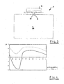
- the FIG. 1 shows a baking oven 1 with a baking muffle 2, wherein above the baking muffle 2 a cross-flow fan 3 with a subsequent cooling air duct 4 generates a cooling air flow, the discharge takes place in the open.
- the mouth region 5 of a vapor withdrawal channel 6 is arranged directly in the vicinity of the blow-out region 7 of the cross-flow fan 3.
- a pumping speed for the vapor from the vapor outlet channel 6 a arises at an empirically determined minimum speed of the fan 8, a pumping speed for the vapor from the vapor outlet channel 6 a.
- the mouth region 5 is arranged in the flow direction of the cooling air flow behind the impeller 8, which is only hinted at here.
- the mouth region 5 is arranged relative to the cross-flow fan 3 such that the pumping speed is greatest at the maximum rotational speed of the cross-flow fan 3.
- an exhaust air duct 9 for discharging the mixed air flow from cooling air and vapor can be attached to the blow-out region 7 of the cross-flow fan 3.
- the cross-flow fan 3 is arranged with a suction opening 10 for the mouth region 5 of the vapor withdrawal channel 6 on a mounting part 11, wherein the mounting part 11 for this purpose has a corresponding opening 10 to the suction port.
- the mounting part 11 in its functional effect is better seen in the FIG. 3 , Of the Cross-flow fan 3 is fixed by means of the mounting part 11 in a simple manner to the rest of the oven 1.
- the jacket region 12 of the cross-flow fan 3 is provided with letters from "A" to "L". These letters indicate the pressure measurement points of tests performed and are also plotted on the x-axis in the diagrams below, from “A” to "L”. On the Y-axis, the pressure conditions, ie overpressure or negative pressure, indicated that set at maximum speed of the cross-flow fan 3.
- the range from "A" to about "D" of the blow-out 7 a Represents suction zone.
- FIG. 4 shows a further graph, wherein in the graph on the X-axis, the measuring points "A" to "L" of the lateral surface 12 of the cross-flow fan 3 are plotted, wherein the solid line represents the suction pressure behavior of the cross-flow fan 3, if he with his Maximum speed is operated. Recognizable in the graph is a pumping speed of the cross-flow fan 3 in the region between the first and fourth measuring point. If the fan speed is reduced, as shown by the dashed line, the result is also in the range of the first to fourth measuring point "A" to "D” a pressure range.
Landscapes
- Engineering & Computer Science (AREA)
- Chemical & Material Sciences (AREA)
- Combustion & Propulsion (AREA)
- Mechanical Engineering (AREA)
- General Engineering & Computer Science (AREA)
- Baking, Grill, Roasting (AREA)
- Electric Ovens (AREA)
- Muffle Furnaces And Rotary Kilns (AREA)
Claims (5)
- Four (1) avec un moufle de four (2) et un ventilateur à flux transversal (3) avec une roue de ventilateur (8), dans lequel le ventilateur à flux transversal (3) produit, avec un canal d'air de refroidissement (4) attenant, un flux d'air de refroidissement dont l'évacuation s'effectue à l'air libre, et dans lequel un canal d'extraction des vapeurs (6) débouche dans le canal d'air de refroidissement (4), canal d'extraction des vapeurs à travers lequel les vapeurs peuvent être aspirées à partir du moufle de four (2), dans lequel le ventilateur à flux transversal (3) présente une zone de soufflage (7), caractérisé en ce que, dans la zone d'enveloppe (12) du ventilateur à flux transversal (3), à proximité de la zone de soufflage (7), pour une vitesse de rotation minimale de la roue de ventilateur (8), il apparaît une zone d'aspiration (A, ..., D) dans laquelle se trouve la zone d'embouchure (5) du canal d'extraction des vapeurs (6).
- Four selon la revendication 1,
caractérisé en ce que,
à proximité de la zone de soufflage (7), le carter du ventilateur à flux transversal (3) présente une ouverture d'aspiration (10) à laquelle est couplé le canal d'extraction des vapeurs (6). - Four selon les revendications 1 et 2,
caractérisé en ce que
la zone d'embouchure (5) est disposée derrière la roue de ventilateur (8) dans la direction d'écoulement du flux d'air de refroidissement. - Four selon les revendications 1 à 3,
caractérisé en ce que,
pour l'évacuation du flux d'air mixte composé de l'air de refroidissement et des vapeurs, un canal d'air d'échappement (9) est joint à la zone de soufflage (7) du ventilateur à flux transversal (3). - Four selon les revendications 1 à 4,
caractérisé en ce que
le ventilateur à flux transversal (3) avec l'ouverture d'aspiration (10) pour la zone d'embouchure (5) du canal d'extraction des vapeurs (6) est disposé sur une partie de montage (11), dans lequel la partie de montage (11) présente une ouverture à cet effet.
Applications Claiming Priority (1)
| Application Number | Priority Date | Filing Date | Title |
|---|---|---|---|
| DE200610047587 DE102006047587A1 (de) | 2006-10-05 | 2006-10-05 | Backofen mit einer Backmuffel und einem Querstromlüfter |
Publications (3)
| Publication Number | Publication Date |
|---|---|
| EP1909037A2 EP1909037A2 (fr) | 2008-04-09 |
| EP1909037A3 EP1909037A3 (fr) | 2010-12-22 |
| EP1909037B1 true EP1909037B1 (fr) | 2015-11-11 |
Family
ID=38895539
Family Applications (1)
| Application Number | Title | Priority Date | Filing Date |
|---|---|---|---|
| EP07018245.6A Not-in-force EP1909037B1 (fr) | 2006-10-05 | 2007-09-18 | Four de cuisson doté d'un moufle et d'un ventilateur à courant transversal |
Country Status (3)
| Country | Link |
|---|---|
| US (1) | US8950389B2 (fr) |
| EP (1) | EP1909037B1 (fr) |
| DE (1) | DE102006047587A1 (fr) |
Families Citing this family (12)
| Publication number | Priority date | Publication date | Assignee | Title |
|---|---|---|---|---|
| WO2011013801A1 (fr) * | 2009-07-30 | 2011-02-03 | シャープ株式会社 | Dispositif de cuisson |
| EP2463587B1 (fr) | 2010-12-13 | 2018-04-04 | BSH Hausgeräte GmbH | Appareil de cuisson |
| USD787041S1 (en) | 2015-09-17 | 2017-05-16 | Whirlpool Corporation | Gas burner |
| US10837651B2 (en) | 2015-09-24 | 2020-11-17 | Whirlpool Corporation | Oven cavity connector for operating power accessory trays for cooking appliance |
| US11777190B2 (en) | 2015-12-29 | 2023-10-03 | Whirlpool Corporation | Appliance including an antenna using a portion of appliance as a ground plane |
| US10145568B2 (en) | 2016-06-27 | 2018-12-04 | Whirlpool Corporation | High efficiency high power inner flame burner |
| US10551056B2 (en) | 2017-02-23 | 2020-02-04 | Whirlpool Corporation | Burner base |
| US10451290B2 (en) | 2017-03-07 | 2019-10-22 | Whirlpool Corporation | Forced convection steam assembly |
| US10660162B2 (en) | 2017-03-16 | 2020-05-19 | Whirlpool Corporation | Power delivery system for an induction cooktop with multi-output inverters |
| US10627116B2 (en) | 2018-06-26 | 2020-04-21 | Whirlpool Corporation | Ventilation system for cooking appliance |
| US10619862B2 (en) | 2018-06-28 | 2020-04-14 | Whirlpool Corporation | Frontal cooling towers for a ventilation system of a cooking appliance |
| US10837652B2 (en) | 2018-07-18 | 2020-11-17 | Whirlpool Corporation | Appliance secondary door |
Family Cites Families (7)
| Publication number | Priority date | Publication date | Assignee | Title |
|---|---|---|---|---|
| DE2656565B2 (de) | 1976-12-14 | 1979-07-12 | Bosch-Siemens Hausgeraete Gmbh, 7000 Stuttgart | Backofen mit einem Wrasenabzugskanal |
| DE3741975A1 (de) | 1987-12-11 | 1989-06-22 | Buderus Kuechentechnik | Vorrichtung zur steuerung eines mit dampf betriebenen gargeraetes und vorrichtung zum betreiben eines solchen geraetes |
| DE4238660C2 (de) * | 1992-11-16 | 1994-09-01 | Bosch Siemens Hausgeraete | Backofen, insbesondere mit einer Einrichtung für pyrolytische Selbstreinigung |
| FR2714959A1 (fr) * | 1994-01-12 | 1995-07-13 | Scholtes Ets Eugen | Four de cuisson domestique. |
| DE4407702A1 (de) | 1994-03-08 | 1995-11-30 | Bosch Siemens Hausgeraete | Vorrichtung zum Abführen von Wrasen aus einem Backofen |
| DE19509569A1 (de) | 1995-03-16 | 1996-09-19 | Wiesheu Wiwa Gmbh | Ofen zur Wärmebehandlung von Lebensmitteln und Verfahren zum Backen |
| US5918589A (en) * | 1996-05-10 | 1999-07-06 | Whirlpool Corporation | Low moisture/closed door broil oven ventilation system |
-
2006
- 2006-10-05 DE DE200610047587 patent/DE102006047587A1/de not_active Ceased
-
2007
- 2007-09-18 EP EP07018245.6A patent/EP1909037B1/fr not_active Not-in-force
- 2007-10-05 US US11/867,902 patent/US8950389B2/en not_active Expired - Fee Related
Also Published As
| Publication number | Publication date |
|---|---|
| DE102006047587A1 (de) | 2008-04-10 |
| US20080083400A1 (en) | 2008-04-10 |
| US8950389B2 (en) | 2015-02-10 |
| EP1909037A3 (fr) | 2010-12-22 |
| EP1909037A2 (fr) | 2008-04-09 |
Similar Documents
| Publication | Publication Date | Title |
|---|---|---|
| EP1909037B1 (fr) | Four de cuisson doté d'un moufle et d'un ventilateur à courant transversal | |
| EP3953645B1 (fr) | Dispositif pour faire chauffer un aliment à cuire | |
| DE69605796T2 (de) | Abzugssystem für küchen | |
| EP4080123A1 (fr) | Hotte aspirante destinée à l'aspiration des vapeurs de cuisson vers le bas | |
| DE2837543A1 (de) | Dunstabzugsvorrichtung | |
| DE202007012095U1 (de) | Gleichluftsystem für eine Abzugshaube, insbesondere zur Anwendung an einem Kochfeld | |
| DE2525865A1 (de) | Ventilator | |
| EP3334942B1 (fr) | Hotte avec une ventilateur diagonal | |
| DE10325007A1 (de) | Abzugshaube für einen Küchenherd | |
| DE1503510A1 (de) | Ventilator | |
| WO2008113664A2 (fr) | Hotte aspirante | |
| EP2567641B1 (fr) | Appareil de cuisson sous pression avec conduite d'échappement de vapeur et injection d'eau | |
| DE102017216456A1 (de) | Lüftungsvorrichtung für Kochfeld und Kochfeld mit Lüftungsvorrichtung | |
| EP2857758B1 (fr) | Dispositif d'aspiration de vapeur | |
| EP3963266B1 (fr) | Dispositif d'évacuation de vapeur, ustensile de cuisine comportant une plaque de cuisson et dispositif d'évacuation de vapeur et procédé pour faire fonctionner un dispositif d'évacuation de vapeur | |
| DE102011112829B4 (de) | Druckgargerät mit einer Rohrleitung für entweichenden Dampf und einer Wassereinspritzung | |
| DE2650435A1 (de) | Ventilationsabzug | |
| EP3807576B1 (fr) | Appareil de cuisson | |
| DE102012012551A1 (de) | Lüftungsanordnung mit einer Dunstabzugshaube | |
| EP2463587B1 (fr) | Appareil de cuisson | |
| DE102017131168A1 (de) | Dunstabzugshaube mit rundem Einströmungsbereich in schräger Führungsfläche | |
| DE19950817A1 (de) | Dunstabzugsvorrichtung | |
| DE102019100046B4 (de) | Kochfeldsystem | |
| DE102017201906A1 (de) | Dunstabzugsvorrichtung mit Filterelement | |
| EP3574265B1 (fr) | Hotte aspirante |
Legal Events
| Date | Code | Title | Description |
|---|---|---|---|
| PUAI | Public reference made under article 153(3) epc to a published international application that has entered the european phase |
Free format text: ORIGINAL CODE: 0009012 |
|
| AK | Designated contracting states |
Kind code of ref document: A2 Designated state(s): AT BE BG CH CY CZ DE DK EE ES FI FR GB GR HU IE IS IT LI LT LU LV MC MT NL PL PT RO SE SI SK TR |
|
| AX | Request for extension of the european patent |
Extension state: AL BA HR MK RS |
|
| PUAL | Search report despatched |
Free format text: ORIGINAL CODE: 0009013 |
|
| AK | Designated contracting states |
Kind code of ref document: A3 Designated state(s): AT BE BG CH CY CZ DE DK EE ES FI FR GB GR HU IE IS IT LI LT LU LV MC MT NL PL PT RO SE SI SK TR |
|
| AX | Request for extension of the european patent |
Extension state: AL BA HR MK RS |
|
| 17P | Request for examination filed |
Effective date: 20110510 |
|
| AKX | Designation fees paid |
Designated state(s): AT BE BG CH CY CZ DE DK EE ES FI FR GB GR HU IE IS IT LI LT LU LV MC MT NL PL PT RO SE SI SK TR |
|
| 17Q | First examination report despatched |
Effective date: 20111123 |
|
| GRAP | Despatch of communication of intention to grant a patent |
Free format text: ORIGINAL CODE: EPIDOSNIGR1 |
|
| INTG | Intention to grant announced |
Effective date: 20150515 |
|
| RIN1 | Information on inventor provided before grant (corrected) |
Inventor name: ROTHENBACHER, HELMUT Inventor name: SILLMEN, ULRICH DR. Inventor name: HORSTKOETTER, ANDREAS Inventor name: OBERROEHRMANN, AUGUST |
|
| GRAS | Grant fee paid |
Free format text: ORIGINAL CODE: EPIDOSNIGR3 |
|
| GRAA | (expected) grant |
Free format text: ORIGINAL CODE: 0009210 |
|
| AK | Designated contracting states |
Kind code of ref document: B1 Designated state(s): AT BE BG CH CY CZ DE DK EE ES FI FR GB GR HU IE IS IT LI LT LU LV MC MT NL PL PT RO SE SI SK TR |
|
| REG | Reference to a national code |
Ref country code: GB Ref legal event code: FG4D Free format text: NOT ENGLISH |
|
| REG | Reference to a national code |
Ref country code: CH Ref legal event code: EP |
|
| REG | Reference to a national code |
Ref country code: DE Ref legal event code: R084 Ref document number: 502007014382 Country of ref document: DE |
|
| REG | Reference to a national code |
Ref country code: IE Ref legal event code: FG4D Free format text: LANGUAGE OF EP DOCUMENT: GERMAN |
|
| REG | Reference to a national code |
Ref country code: AT Ref legal event code: REF Ref document number: 760655 Country of ref document: AT Kind code of ref document: T Effective date: 20151215 |
|
| REG | Reference to a national code |
Ref country code: DE Ref legal event code: R096 Ref document number: 502007014382 Country of ref document: DE |
|
| REG | Reference to a national code |
Ref country code: LT Ref legal event code: MG4D |
|
| REG | Reference to a national code |
Ref country code: NL Ref legal event code: MP Effective date: 20160211 |
|
| PG25 | Lapsed in a contracting state [announced via postgrant information from national office to epo] |
Ref country code: ES Free format text: LAPSE BECAUSE OF FAILURE TO SUBMIT A TRANSLATION OF THE DESCRIPTION OR TO PAY THE FEE WITHIN THE PRESCRIBED TIME-LIMIT Effective date: 20151111 Ref country code: IT Free format text: LAPSE BECAUSE OF FAILURE TO SUBMIT A TRANSLATION OF THE DESCRIPTION OR TO PAY THE FEE WITHIN THE PRESCRIBED TIME-LIMIT Effective date: 20151111 Ref country code: IS Free format text: LAPSE BECAUSE OF FAILURE TO SUBMIT A TRANSLATION OF THE DESCRIPTION OR TO PAY THE FEE WITHIN THE PRESCRIBED TIME-LIMIT Effective date: 20160311 Ref country code: NL Free format text: LAPSE BECAUSE OF FAILURE TO SUBMIT A TRANSLATION OF THE DESCRIPTION OR TO PAY THE FEE WITHIN THE PRESCRIBED TIME-LIMIT Effective date: 20151111 Ref country code: LT Free format text: LAPSE BECAUSE OF FAILURE TO SUBMIT A TRANSLATION OF THE DESCRIPTION OR TO PAY THE FEE WITHIN THE PRESCRIBED TIME-LIMIT Effective date: 20151111 |
|
| PG25 | Lapsed in a contracting state [announced via postgrant information from national office to epo] |
Ref country code: PL Free format text: LAPSE BECAUSE OF FAILURE TO SUBMIT A TRANSLATION OF THE DESCRIPTION OR TO PAY THE FEE WITHIN THE PRESCRIBED TIME-LIMIT Effective date: 20151111 Ref country code: PT Free format text: LAPSE BECAUSE OF FAILURE TO SUBMIT A TRANSLATION OF THE DESCRIPTION OR TO PAY THE FEE WITHIN THE PRESCRIBED TIME-LIMIT Effective date: 20160311 Ref country code: GR Free format text: LAPSE BECAUSE OF FAILURE TO SUBMIT A TRANSLATION OF THE DESCRIPTION OR TO PAY THE FEE WITHIN THE PRESCRIBED TIME-LIMIT Effective date: 20160212 Ref country code: FI Free format text: LAPSE BECAUSE OF FAILURE TO SUBMIT A TRANSLATION OF THE DESCRIPTION OR TO PAY THE FEE WITHIN THE PRESCRIBED TIME-LIMIT Effective date: 20151111 Ref country code: LV Free format text: LAPSE BECAUSE OF FAILURE TO SUBMIT A TRANSLATION OF THE DESCRIPTION OR TO PAY THE FEE WITHIN THE PRESCRIBED TIME-LIMIT Effective date: 20151111 Ref country code: SE Free format text: LAPSE BECAUSE OF FAILURE TO SUBMIT A TRANSLATION OF THE DESCRIPTION OR TO PAY THE FEE WITHIN THE PRESCRIBED TIME-LIMIT Effective date: 20151111 |
|
| PG25 | Lapsed in a contracting state [announced via postgrant information from national office to epo] |
Ref country code: CZ Free format text: LAPSE BECAUSE OF FAILURE TO SUBMIT A TRANSLATION OF THE DESCRIPTION OR TO PAY THE FEE WITHIN THE PRESCRIBED TIME-LIMIT Effective date: 20151111 |
|
| REG | Reference to a national code |
Ref country code: DE Ref legal event code: R097 Ref document number: 502007014382 Country of ref document: DE |
|
| PG25 | Lapsed in a contracting state [announced via postgrant information from national office to epo] |
Ref country code: EE Free format text: LAPSE BECAUSE OF FAILURE TO SUBMIT A TRANSLATION OF THE DESCRIPTION OR TO PAY THE FEE WITHIN THE PRESCRIBED TIME-LIMIT Effective date: 20151111 Ref country code: DK Free format text: LAPSE BECAUSE OF FAILURE TO SUBMIT A TRANSLATION OF THE DESCRIPTION OR TO PAY THE FEE WITHIN THE PRESCRIBED TIME-LIMIT Effective date: 20151111 Ref country code: SK Free format text: LAPSE BECAUSE OF FAILURE TO SUBMIT A TRANSLATION OF THE DESCRIPTION OR TO PAY THE FEE WITHIN THE PRESCRIBED TIME-LIMIT Effective date: 20151111 Ref country code: RO Free format text: LAPSE BECAUSE OF FAILURE TO SUBMIT A TRANSLATION OF THE DESCRIPTION OR TO PAY THE FEE WITHIN THE PRESCRIBED TIME-LIMIT Effective date: 20151111 |
|
| PLBE | No opposition filed within time limit |
Free format text: ORIGINAL CODE: 0009261 |
|
| STAA | Information on the status of an ep patent application or granted ep patent |
Free format text: STATUS: NO OPPOSITION FILED WITHIN TIME LIMIT |
|
| 26N | No opposition filed |
Effective date: 20160812 |
|
| PG25 | Lapsed in a contracting state [announced via postgrant information from national office to epo] |
Ref country code: SI Free format text: LAPSE BECAUSE OF FAILURE TO SUBMIT A TRANSLATION OF THE DESCRIPTION OR TO PAY THE FEE WITHIN THE PRESCRIBED TIME-LIMIT Effective date: 20151111 |
|
| PG25 | Lapsed in a contracting state [announced via postgrant information from national office to epo] |
Ref country code: BE Free format text: LAPSE BECAUSE OF NON-PAYMENT OF DUE FEES Effective date: 20160930 |
|
| PG25 | Lapsed in a contracting state [announced via postgrant information from national office to epo] |
Ref country code: MC Free format text: LAPSE BECAUSE OF FAILURE TO SUBMIT A TRANSLATION OF THE DESCRIPTION OR TO PAY THE FEE WITHIN THE PRESCRIBED TIME-LIMIT Effective date: 20151111 |
|
| REG | Reference to a national code |
Ref country code: CH Ref legal event code: PL |
|
| GBPC | Gb: european patent ceased through non-payment of renewal fee |
Effective date: 20160918 |
|
| REG | Reference to a national code |
Ref country code: IE Ref legal event code: MM4A |
|
| REG | Reference to a national code |
Ref country code: FR Ref legal event code: ST Effective date: 20170531 |
|
| PG25 | Lapsed in a contracting state [announced via postgrant information from national office to epo] |
Ref country code: FR Free format text: LAPSE BECAUSE OF NON-PAYMENT OF DUE FEES Effective date: 20160930 Ref country code: CH Free format text: LAPSE BECAUSE OF NON-PAYMENT OF DUE FEES Effective date: 20160930 Ref country code: IE Free format text: LAPSE BECAUSE OF NON-PAYMENT OF DUE FEES Effective date: 20160918 Ref country code: LI Free format text: LAPSE BECAUSE OF NON-PAYMENT OF DUE FEES Effective date: 20160930 Ref country code: GB Free format text: LAPSE BECAUSE OF NON-PAYMENT OF DUE FEES Effective date: 20160918 |
|
| PG25 | Lapsed in a contracting state [announced via postgrant information from national office to epo] |
Ref country code: LU Free format text: LAPSE BECAUSE OF NON-PAYMENT OF DUE FEES Effective date: 20160918 |
|
| REG | Reference to a national code |
Ref country code: AT Ref legal event code: MM01 Ref document number: 760655 Country of ref document: AT Kind code of ref document: T Effective date: 20160918 |
|
| REG | Reference to a national code |
Ref country code: BE Ref legal event code: MM Effective date: 20160930 |
|
| PG25 | Lapsed in a contracting state [announced via postgrant information from national office to epo] |
Ref country code: AT Free format text: LAPSE BECAUSE OF NON-PAYMENT OF DUE FEES Effective date: 20160918 |
|
| PG25 | Lapsed in a contracting state [announced via postgrant information from national office to epo] |
Ref country code: CY Free format text: LAPSE BECAUSE OF FAILURE TO SUBMIT A TRANSLATION OF THE DESCRIPTION OR TO PAY THE FEE WITHIN THE PRESCRIBED TIME-LIMIT Effective date: 20151111 Ref country code: HU Free format text: LAPSE BECAUSE OF FAILURE TO SUBMIT A TRANSLATION OF THE DESCRIPTION OR TO PAY THE FEE WITHIN THE PRESCRIBED TIME-LIMIT; INVALID AB INITIO Effective date: 20070918 |
|
| PG25 | Lapsed in a contracting state [announced via postgrant information from national office to epo] |
Ref country code: TR Free format text: LAPSE BECAUSE OF FAILURE TO SUBMIT A TRANSLATION OF THE DESCRIPTION OR TO PAY THE FEE WITHIN THE PRESCRIBED TIME-LIMIT Effective date: 20151111 Ref country code: MT Free format text: LAPSE BECAUSE OF FAILURE TO SUBMIT A TRANSLATION OF THE DESCRIPTION OR TO PAY THE FEE WITHIN THE PRESCRIBED TIME-LIMIT Effective date: 20151111 |
|
| PG25 | Lapsed in a contracting state [announced via postgrant information from national office to epo] |
Ref country code: BG Free format text: LAPSE BECAUSE OF FAILURE TO SUBMIT A TRANSLATION OF THE DESCRIPTION OR TO PAY THE FEE WITHIN THE PRESCRIBED TIME-LIMIT Effective date: 20151111 |
|
| PGFP | Annual fee paid to national office [announced via postgrant information from national office to epo] |
Ref country code: DE Payment date: 20200930 Year of fee payment: 14 |
|
| REG | Reference to a national code |
Ref country code: DE Ref legal event code: R119 Ref document number: 502007014382 Country of ref document: DE |
|
| PG25 | Lapsed in a contracting state [announced via postgrant information from national office to epo] |
Ref country code: DE Free format text: LAPSE BECAUSE OF NON-PAYMENT OF DUE FEES Effective date: 20220401 |