EP1909537A2 - Système et procédé de coupe à ligne ellipsoïdale pour la conception d'une coquille de prothèse auditive - Google Patents
Système et procédé de coupe à ligne ellipsoïdale pour la conception d'une coquille de prothèse auditive Download PDFInfo
- Publication number
- EP1909537A2 EP1909537A2 EP07115732A EP07115732A EP1909537A2 EP 1909537 A2 EP1909537 A2 EP 1909537A2 EP 07115732 A EP07115732 A EP 07115732A EP 07115732 A EP07115732 A EP 07115732A EP 1909537 A2 EP1909537 A2 EP 1909537A2
- Authority
- EP
- European Patent Office
- Prior art keywords
- hearing aid
- contour
- line cut
- aid shell
- cut plane
- Prior art date
- Legal status (The legal status is an assumption and is not a legal conclusion. Google has not performed a legal analysis and makes no representation as to the accuracy of the status listed.)
- Withdrawn
Links
Images




Classifications
-
- H—ELECTRICITY
- H04—ELECTRIC COMMUNICATION TECHNIQUE
- H04R—LOUDSPEAKERS, MICROPHONES, GRAMOPHONE PICK-UPS OR LIKE ACOUSTIC ELECTROMECHANICAL TRANSDUCERS; ELECTRIC HEARING AIDS; PUBLIC ADDRESS SYSTEMS
- H04R25/00—Electric hearing aids
- H04R25/65—Housing parts, e.g. shells, tips or moulds, or their manufacture
- H04R25/652—Ear tips; Ear moulds
-
- H—ELECTRICITY
- H04—ELECTRIC COMMUNICATION TECHNIQUE
- H04R—LOUDSPEAKERS, MICROPHONES, GRAMOPHONE PICK-UPS OR LIKE ACOUSTIC ELECTROMECHANICAL TRANSDUCERS; ELECTRIC HEARING AIDS; PUBLIC ADDRESS SYSTEMS
- H04R25/00—Electric hearing aids
- H04R25/65—Housing parts, e.g. shells, tips or moulds, or their manufacture
- H04R25/658—Manufacture of housing parts
-
- H—ELECTRICITY
- H04—ELECTRIC COMMUNICATION TECHNIQUE
- H04R—LOUDSPEAKERS, MICROPHONES, GRAMOPHONE PICK-UPS OR LIKE ACOUSTIC ELECTROMECHANICAL TRANSDUCERS; ELECTRIC HEARING AIDS; PUBLIC ADDRESS SYSTEMS
- H04R2225/00—Details of deaf aids covered by H04R25/00, not provided for in any of its subgroups
- H04R2225/77—Design aspects, e.g. CAD, of hearing aid tips, moulds or housings
-
- H—ELECTRICITY
- H04—ELECTRIC COMMUNICATION TECHNIQUE
- H04R—LOUDSPEAKERS, MICROPHONES, GRAMOPHONE PICK-UPS OR LIKE ACOUSTIC ELECTROMECHANICAL TRANSDUCERS; ELECTRIC HEARING AIDS; PUBLIC ADDRESS SYSTEMS
- H04R25/00—Electric hearing aids
- H04R25/65—Housing parts, e.g. shells, tips or moulds, or their manufacture
-
- Y—GENERAL TAGGING OF NEW TECHNOLOGICAL DEVELOPMENTS; GENERAL TAGGING OF CROSS-SECTIONAL TECHNOLOGIES SPANNING OVER SEVERAL SECTIONS OF THE IPC; TECHNICAL SUBJECTS COVERED BY FORMER USPC CROSS-REFERENCE ART COLLECTIONS [XRACs] AND DIGESTS
- Y10—TECHNICAL SUBJECTS COVERED BY FORMER USPC
- Y10T—TECHNICAL SUBJECTS COVERED BY FORMER US CLASSIFICATION
- Y10T29/00—Metal working
- Y10T29/49—Method of mechanical manufacture
- Y10T29/4957—Sound device making
- Y10T29/49572—Hearing aid component making
Definitions
- the present invention is directed to a system and method for cutting hearing aid shells using an ellipsoidal line cut methodology.
- Hearing aid shells that house various hearing aid components are designed to fit into the ear of a wearer.
- each user's ear is shaped differently so that a one-size-fits all approach cannot be used or would result in a poor fit and cause discomfort for the wearer. For this reason, customized shells are created that correspond to the particular shape of the user's ear.
- an impression of the user's ear is taken using a soft moldable material that conforms to the shape of the user's ear which subsequently hardens. This impression can then be used to create a hearing aid shell design that precisely matches the user's ear, resulting in a good fit and comfort for the wearer.
- Figure 1A illustrates a typical digitized model of a hearing aid shell 10 to which a bottom cut plane 50 ( Figure 2) has been applied, creating a bottom cut contour 52.
- FIG. 2 illustrates known application of the Bottom Cut Plane 50 to the hearing aid shell 10.
- a hearing aid shell 10 has a Bottom Cut Plane 50, which defines the border of the bottom opening of the shell 10.
- the shell 10 After a scanning/triangulation of the shell 10, which creates a 3D digital definition of a shell shape, the shell 10 typically has a non-planar contour which defines the Bottom of the Shell.
- the Bottom Cut Plane 50 is introduced which defines a new topology of the shell opening contour (Bottom Cut Plane Contour) 52, which is defined as the intersection between the shell 10 and the Bottom Cut Plane 50.
- the remove portion 14, i.e., the material below the plane 50 is removed and all holes between the plane 50 and the keep portion 12 of the remaining shell are filled with material.
- One of the basic detailing and modeling procedures is to utilize what is know as a line cut plane that is used to define a cut plane for detailing operations, separating the shell 10 along a planar boundary into a keep portion 12 and a remove portion 14, producing a Line Cut Plane contour 62.
- the face that is created by the cut plane must be filled in order to create a coherent shell. Theoretically, filling could be performed by simply applying the plane as an actual part of the shell. In the real world, this would create sharp edges and unpleasant aesthetics that are not practical. Therefore, various techniques have been applied to adapt the surface 64 created by the line cut plane into a more practical shape.
- Figure 1C illustrates the application of a rounding process where the cutting area defined by the cut plane has been filled and rounded according to certain defined parameters.
- a modification of this technique can be to provide the rounding function that includes an offset plane which provides boundaries to the rounding operation (see Figure 1E).
- Figure 1 D illustrates the application of an alternate tapering process, which serves to remove a tip area of the shell with a smoothing bounding area, such that after the cut plane is applied and filled, a smoothing operation is performed.
- Prahl Tapering is a refinement of the tapering that utilizes an offset plane to further define a rounding effect.
- Helix Tapering is used to reshape the helix material of the shell with a rounding effect, according to various parameters.
- a “Prahl Taper” refers to a polynomial shrink of the canal of the shell impression usually initiated from the aperture to the canal tip. It is characterized by an erosion parameter, which is the measure of the required shrink and a maximum reduction parameter, which determines the required reduction in canal length.
- a “Helix Taper” refers to a polynomial shrink of the helix which begins at the highest point on the helix to a user defined position of the helix.
- a system and appertaining algorithm for providing an improved cutting and shaping of the hearing aid shell using an Ellipsoidal Line Cut is provided that increases the speed of detailing operations and enables a creation of more cosmetically appealing shells.
- the shell looks more cosmetically appealing than conventional cuts since the visibility of such a cut is minimized or eliminated; the application of the Ellipsoidal Line Cut reduces the shell size.
- the use of the ellipsoidal cut is substantially advanced over the previous shaping techniques that had been used.
- a method for trimming a hearing aid shell comprising: producing a 3D data definition of an original hearing aid shell design; establishing a line cut plane that is not parallel to a bottom cut plane, thereby defining a line cut plane contour by an intersection of the line cut plane and the hearing aid shell; creating a projected contour on the bottom cut plane that corresponds in shape to a portion of the line cut plane contour; defining a line cut surface between the portion of the line cut plane contour and the projected contour; identifying a first portion of the hearing aid shell on one side of the line cut surface as a keep portion of the hearing aid shell, and second portion of the hearing aid shell on the other side of the line cut surface as a removal portion of the hearing aid shell, a new hearing aid shell design being defined by the keep portion of the hearing aid shell; eliminating parts of the new hearing aid shell design that extend beyond boundaries defined by the original hearing aid shell design; and producing a hearing aid shell corresponding to the new hearing aid shell design.
- a system for trimming a hearing aid shell, comprising: a computer system having a processor, user input device, user display device, data storage device, and communications device; a line cut algorithm for establishing a line cut plane in a 3D model of an original hearing aid shell design that is not parallel to a bottom cut plane of the hearing aid shell; a contour algorithm for determining a projected contour on the bottom cut plane that corresponds in shape to a portion of the line cut plane contour; a merger algorithm for defining a line cut surface between the portion of the line cut plane contour and the projected contour, identifying a first portion of the hearing aid shell on one side of the line cut surface as a keep portion of the hearing aid shell, and second portion of the hearing aid shell on the other side of the line cut surface as a removal portion of the hearing aid shell, a new hearing aid shell design being defined by the keep portion of the hearing aid shell; and an elimination algorithm for eliminating parts of the new hearing aid shell design that extend beyond boundaries defined by the original hearing aid shell design.
- a hearing aid shell comprising: a line cut surface comprising a border contour divided into a first contour portion and a second contour portion, the first and second contour portions completely defining the border contour, wherein: the first contour portion has a first shape; and the second contour portion has a second shape lying in a bottom cut surface that is not parallel to the line cut surface, the second shape being identical to the first shape except that is flattened by a shrinking ratio.
- the algorithms for execution on a processor can be stored on a computer readable media.
- the advantage of having shell looking like as if it has shrunken, instead of cut, is that in after performing the ellipsoidal line cut, the operator of the detailing software does not have to worry about how the shell looks like after his cut and whether it is "edgy" (i.e., contains unattractive rounded edges) or not.
- the operator can concentrate on making a shell of the correct size with the appropirate cuts and does not have to worry about whether the shell looks edgy or not (since a hearing aid that looks like a box with rounded edges is less aesthetically pleasing, and hence, less marketable, than one that has been created using the ellipsoidal line cut.
- the algorithm accepts the following inputs: a mathematical 3D definition of a hearing aid shell; a mathematical definition of a Bottom Cut Plane and a Line Cut Plane; and, ashrinking Ratio.
- the result of applying the algorithm to the shell is a shell with a modified shape at the place where Ellipsoidal LineCut was applied. The rest of the shell remains untouched.
- the algorithm can function both on hollowed and unhollowed shells; it is used to cut the parts of the shell where the Ellipsoidal Line Cut Pivot Axis intersects with the shell.
- the present system and method are designed to provide a mechanism for simplifying the design of a hearing aid shell, potentially serving to replace the use of Helix Tapering, Prahl Tapering, Rounding, Tapering, and Rounding with Offset in this context.
- the algorithm can be operated on a standard computer system having a central processing unit, user input and output devices, data storage, and mechanisms for remote communications. With current technology, the algorithm can operate in under five seconds and can be designed to run independent of any particular platform.
- Figure 3A illustrates the measurement-based nature of the Ellipsoidal Line Cut.
- the shell design in general is based on required measurements for a particular shell for a user. For instance, detailing operators know that in order to create a half shell design, they need to ensure, e.g., that the distance from intertragal notch in the direction of helix is limited to 14 mm or some other defined value. Such a limit could be required, for instance, by the fact that the standard electronics module used for such a shell type requires a particular amount of space to fit in. Or, for instance, industry standards will not allow considering a shell bigger then 14 mm in one of the directions as a half shell, but instead would consider this as a full-shell (which is cheaper in the marketplace).
- the Line Cut Plane 60 of the shell is illustrated with the respective keep portion 12 and remove portion 14 of the hearing aid shell 10.
- Figure 3B is a top view of what is shown in Figure 3A.
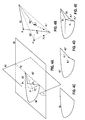
- Figures 4A and 4B illustrate the respective geometries regarding the various planes and contours.
- Figure 5 provides the basic method steps for the operation.
- a hypothetical shell shape which would never be found in practice, is used for ease of illustration.
- the hypothetical shell shape comprises a semi-elliptical cross sectional contour shape 52 in its intersection with the Bottom Cut Plane 50, and comprises a generally triangular cross sectional contour shape 62 in its intersection with a Line Cut Plane 60.
- a line cut plane is established by the operator 104.
- the Line Cut Plane 60 intersects the shell 10, and indicates, via a vector normal to this plane, which part of the shell 10 is preserved and which part is removed. Only the respective Bottom Cut Plane Contour 52 and Line Cut Plane Contour 62 of the shell are shown for the sake of clarity.
- the Line Cut Plane Contour 62 is divided into a moving part and a fixed part. All points of the Shell Line Cut Plane Contour 62 lying on the Bottom Cut Plane 50, i.e. along an ellipsoidal Line Cut Pivot Axis 70 (defined as the intersection of the Bottom Cut Plane 50 and the line cut plane 60), belong to the fixed part which implies that no transformation needs to be applied to them. All other points of the Shell Line Cut Plane Contour 62 belong to the moving part and the following operations are applied to them.
- a shrinking operation 108 is applied on the moving part of the Projected Shell Line Cut Plane Contour 62', which serves to compress or flatten this contour 62'.
- two input values are required: a Shrinking Ratio and ashrinking Direction.
- the Shrinking Ratio which could theoretically be any value between 0 and 1, can be provided manually and directly as an input by the operator, or it can be calculated based on other supplied criteria. In normal operation, this ratio could be based on a desired size of the shell in one of its dimensions as entered by the operator, or it could be determined based on a heuristically-based algorithm that utilizes feature recognition technology.
- Theshrinking direction is always directed towards the Ellipsoidal Line Cut Pivot Axis 70.
- every point P 1 ', P 2 ' of the moving part of the Projected Shell Line Cut Plane Contour 62' is moved in the Shrinking Direction and located to a point P 1 ", P 2 " which is determined by multiplying the Shrinking Ratio by the distance between the current point P 1 ', P 2 ' position and the Ellipsoidal Line Cut Pivot Axis 70, thereby resulting in a Shrunken Projected Shell Line Cut Plane Contour 62",
- Figure 4C illustrates the original Bottom Cut Plan Contour 52
- Figure 4D illustrates the New Bottom Cut Plane Contour 52', which includes the new contour boundary established by the Shrunken Projected Shell Line Cut Plane Contour 62".
- a merge algorithm 110 is subsequently applied, which defines a new Line Cut Surface 64 (Figure 4E) that generally corresponds with the shell surface intersected by the Line Cut Plane 60, but that is adapted to include the New Bottom Cut Plane Contour 52'.
- the Line Cut Plane 60 intersection with the shell is changed into the newly defined surface boundary 64.
- This surface 64 thus serves as a new cutting boundary.
- the merge algorithm 110 can utilize a procedure that accepts two 2D contours 62, 62" as an input and generates a continuous 3D surface 64 connecting the two 2D contours based on the notion that each point (P 1 , P 2 ) in the first 2D contour 62 has a corresponding point (P 1 ", P 2 ") on the second 2D contour 62". This may be accomplished by defining, e.g., a Bezier curve between each corresponding point ((P 1 , P 1 "), (P 2 , P 2 ")) of the contours.
- Figure 4F illustrates one possible procedure in which the surface 64 is generated according to the lines of rotation through the angle ⁇ , but is flattened into ellipses according to the Shrinking Ratio applied.
- mapping techniques may also be utilized for creating the 3D surface from the 2D contours, such as those disclosed in the following references which are provided as background information, all herein incorporated by reference: 1) R. Klein, A. Schilling, W. Straer, Reconstruction and simplification of surfaces from contours; Graph. Models 62 (6) (2000) 429-443 ; 2) Siu-Wing Cheng, Tamal K. Dey, Improved Constructions of Delaunay Based Contour Surfaces (1999), Proc. ACM Sympos. Solid Modeling and Applications 99 1999, 322-323 ; and 3) E. Keppel, Approximating complex surfaces by triangulation of contour lines, IBM J. Res. Dev. 19 (1975) 2-11
- Boolean subtraction is subsequently used 112 to change the original shell shape into a shape that is bounded by the Bottom Cut Plane 50, the new surface boundary 64, and at the same time does not exceed the limits of original impression 52. This is performed by subtracting the previously undetailed shell shape from the newly defined shell shape in order to ensure that no part of the newly generated (by the merge algorithm) surface protrudes outside of the original undetailed impression. This operation ensures that the newly modified shell design will fit into the original ear impression and not cause a fitting problem when the hearing aid is delivered to the end user.
- a test may be provided prior to execution of the algorithm to determine if the input parameters are reasonable. If input parameters are not reasonable for execution of the algorithm, a specific error code containing detailed information about the problem can be returned. Furthermore, various error codes can be determined and provided to a user on the user interface device.
- error codes can include, but are not limited to: 1) the Bottom Cut Plane does not intersect the shell; 2) the Line Cut Plane does not intersect the shell; 3) the shell is hollowed; 4) the shell is corrupted; 5) the Vietnamese Line Cut Pivot Axis does not intersect the shell; 7) the boolean subtraction failed; 8) the merge failed; and 9) the Ellipsoidal Line Cut Contour Transfrmation andshrinking failed.
- an actual hearing aid shell may be produced in accordance with this established configuration.
- the present invention may be described in terms of functional block components and various processing steps. Such functional blocks may be realized by any number of hardware and/or software components configured to perform the specified functions.
- the present invention may employ various integrated circuit components, e.g., memory elements, processing elements, logic elements, look-up tables, and the like, which may carry out a variety of functions under the control of one or more microprocessors or other control devices.
- the elements of the present invention are implemented using software programming or software elements the invention may be implemented with any programming or scripting language such as C, C++, Java, assembler, or the like, with the various algorithms being implemented with any combination of data structures, objects, processes, routines or other programming elements.
- the present invention could employ any number of conventional techniques for electronics configuration, signal processing and/or control, data processing and the like.
Landscapes
- Engineering & Computer Science (AREA)
- Manufacturing & Machinery (AREA)
- Health & Medical Sciences (AREA)
- General Health & Medical Sciences (AREA)
- Neurosurgery (AREA)
- Otolaryngology (AREA)
- Physics & Mathematics (AREA)
- Acoustics & Sound (AREA)
- Signal Processing (AREA)
- Processing Or Creating Images (AREA)
- Image Generation (AREA)
Applications Claiming Priority (1)
| Application Number | Priority Date | Filing Date | Title |
|---|---|---|---|
| US11/538,185 US7680634B2 (en) | 2006-10-03 | 2006-10-03 | Ellipsoidal line cut system and method for hearing aid shell design |
Publications (2)
| Publication Number | Publication Date |
|---|---|
| EP1909537A2 true EP1909537A2 (fr) | 2008-04-09 |
| EP1909537A3 EP1909537A3 (fr) | 2010-04-28 |
Family
ID=38890215
Family Applications (1)
| Application Number | Title | Priority Date | Filing Date |
|---|---|---|---|
| EP07115732A Withdrawn EP1909537A3 (fr) | 2006-10-03 | 2007-09-05 | Système et procédé de coupe à ligne ellipsoïdale pour la conception d'une coquille de prothèse auditive |
Country Status (2)
| Country | Link |
|---|---|
| US (1) | US7680634B2 (fr) |
| EP (1) | EP1909537A3 (fr) |
Cited By (1)
| Publication number | Priority date | Publication date | Assignee | Title |
|---|---|---|---|---|
| EP2986031A1 (fr) * | 2014-08-14 | 2016-02-17 | Oticon A/s | Procédé et système de modélisation d'un embout auriculaire sur mesure |
Families Citing this family (4)
| Publication number | Priority date | Publication date | Assignee | Title |
|---|---|---|---|---|
| EP1875775B1 (fr) * | 2005-03-29 | 2018-11-14 | Sivantos GmbH | Procédé et système de conception d'une coquille de prothèse auditive |
| US20100100362A1 (en) * | 2008-10-10 | 2010-04-22 | Siemens Corporation | Point-Based Shape Matching And Distance Applied To Ear Canal Models |
| US10325418B1 (en) * | 2018-11-15 | 2019-06-18 | Chester Zbigniew Pirzanski | 3D virtual automated modeling of custom posterior concha module |
| NL2023310B1 (en) | 2019-03-21 | 2020-09-28 | Illumina Inc | Training data generation for artificial intelligence-based sequencing |
Citations (3)
| Publication number | Priority date | Publication date | Assignee | Title |
|---|---|---|---|---|
| WO2002030157A2 (fr) | 2000-10-06 | 2002-04-11 | Raindrop Geomagic, Inc. | Procedes et systemes de fabrication permettant une production rapide de coquilles de protheses auditives |
| EP1345470A2 (fr) | 2003-04-03 | 2003-09-17 | Phonak Ag | Procédé de fabrication d'un dispositif électronique portable, adapté à la forme d'une partie du corps d'un individu |
| US20040107080A1 (en) | 2001-03-02 | 2004-06-03 | Nikolaj Deichmann | Method for modelling customised earpieces |
Family Cites Families (5)
| Publication number | Priority date | Publication date | Assignee | Title |
|---|---|---|---|---|
| US7084870B2 (en) * | 2002-12-19 | 2006-08-01 | Siemens Corporate Research, Inc. | Interactive binaural shell modeling for hearing aids |
| US7447556B2 (en) * | 2006-02-03 | 2008-11-04 | Siemens Audiologische Technik Gmbh | System comprising an automated tool and appertaining method for hearing aid design |
| US7991594B2 (en) * | 2005-09-13 | 2011-08-02 | Siemens Corporation | Method and apparatus for the rigid registration of 3D ear impression shapes with skeletons |
| US7979244B2 (en) * | 2005-09-13 | 2011-07-12 | Siemens Corporation | Method and apparatus for aperture detection of 3D hearing aid shells |
| DE102005046169A1 (de) * | 2005-09-27 | 2007-04-05 | Siemens Audiologische Technik Gmbh | Hörhilfegerät mit einer Antenne |
-
2006
- 2006-10-03 US US11/538,185 patent/US7680634B2/en not_active Expired - Fee Related
-
2007
- 2007-09-05 EP EP07115732A patent/EP1909537A3/fr not_active Withdrawn
Patent Citations (3)
| Publication number | Priority date | Publication date | Assignee | Title |
|---|---|---|---|---|
| WO2002030157A2 (fr) | 2000-10-06 | 2002-04-11 | Raindrop Geomagic, Inc. | Procedes et systemes de fabrication permettant une production rapide de coquilles de protheses auditives |
| US20040107080A1 (en) | 2001-03-02 | 2004-06-03 | Nikolaj Deichmann | Method for modelling customised earpieces |
| EP1345470A2 (fr) | 2003-04-03 | 2003-09-17 | Phonak Ag | Procédé de fabrication d'un dispositif électronique portable, adapté à la forme d'une partie du corps d'un individu |
Non-Patent Citations (1)
| Title |
|---|
| R. KLEIN, A. SCHILLING, W. STRAER: "Reconstruction and simplification of surfaces from contours", GRAPH. MODELS, vol. 62, no. 6, 2000, pages 429 - 443 |
Cited By (4)
| Publication number | Priority date | Publication date | Assignee | Title |
|---|---|---|---|---|
| EP2986031A1 (fr) * | 2014-08-14 | 2016-02-17 | Oticon A/s | Procédé et système de modélisation d'un embout auriculaire sur mesure |
| EP2986029A1 (fr) * | 2014-08-14 | 2016-02-17 | Oticon A/s | Méthode et système pour modéliser un embout ajustement personnalisé |
| US9949045B2 (en) | 2014-08-14 | 2018-04-17 | Bernafon Ag | Method and system for modeling a custom fit earmold |
| EP3657820A1 (fr) * | 2014-08-14 | 2020-05-27 | Oticon A/s | Procédé et système de modélisation d'un embout auriculaire sur mesure |
Also Published As
| Publication number | Publication date |
|---|---|
| US20080078082A1 (en) | 2008-04-03 |
| EP1909537A3 (fr) | 2010-04-28 |
| US7680634B2 (en) | 2010-03-16 |
Similar Documents
| Publication | Publication Date | Title |
|---|---|---|
| EP1858293B1 (fr) | Système comprenant un outil automatisé et une méthode adéquate pour un concept d'aide auditive | |
| EP1356709B1 (fr) | Procedes et systemes de fabrication permettant une production rapide de coquilles de protheses auditives | |
| US20020196954A1 (en) | Modeling and fabrication of three-dimensional irregular surfaces for hearing instruments | |
| EP1909537A2 (fr) | Système et procédé de coupe à ligne ellipsoïdale pour la conception d'une coquille de prothèse auditive | |
| CN111991106B (zh) | 一种牙套切割线自动生成方法及应用 | |
| US9652889B2 (en) | Image processing method | |
| WO2002080617A3 (fr) | Systeme assiste par ordinateur destine a concevoir un boitier pour appareil auditif | |
| US7979244B2 (en) | Method and apparatus for aperture detection of 3D hearing aid shells | |
| AU2002211860A1 (en) | Manufacturing methods and systems for rapid production of hearing-aid shells | |
| US7991594B2 (en) | Method and apparatus for the rigid registration of 3D ear impression shapes with skeletons | |
| WO2008107859A1 (fr) | Procédé de calcul automatique de l'enveloppe convexe ou concave d'un ensemble arbitraire de points | |
| EP1915033A2 (fr) | Système et procédé pour effectuer le remplissage sélectif pour une coquille d'aide auditive | |
| EP4352696A1 (fr) | Remplissage d'un trou de maille | |
| DK2048895T3 (en) | Computer-controlled rule-based binaural molding system and method for hearing aid design | |
| EP2023662A1 (fr) | Système comprenant un outil automatisé et une méthode adéquate pour un concept d'aide auditive | |
| KR20230031744A (ko) | 드로잉 툴 기반의 곡선 피팅 방법, 장치 및 기기 | |
| EP2031897A2 (fr) | Procédé de fabrication de coquilles d'aides auditives | |
| CN114145869A (zh) | 义齿贴面制作方法、系统、计算机设备及可读存储介质 | |
| CN119650077B (zh) | 义齿修复体的融合切削方法、设备及存储介质 | |
| CN113920253A (zh) | 一种基于三维口腔模型的牙齿模型快速切割方法 | |
| JP2004516086A (ja) | 車両シートを設計するための方法及び装置 | |
| JP3801792B2 (ja) | 3次元形状の切断装置と切断方法及び切断処理プログラムを格納した記憶媒体 | |
| JP2803975B2 (ja) | 立体モデルの作成装置 | |
| WO2025174914A1 (fr) | Conception indépendante de la géométrie avec formation de surface de maillage natif et conformité de composant variable | |
| JP2002259471A (ja) | 三次元形状作成方法及び三次元形状作成装置 |
Legal Events
| Date | Code | Title | Description |
|---|---|---|---|
| PUAI | Public reference made under article 153(3) epc to a published international application that has entered the european phase |
Free format text: ORIGINAL CODE: 0009012 |
|
| AK | Designated contracting states |
Kind code of ref document: A2 Designated state(s): AT BE BG CH CY CZ DE DK EE ES FI FR GB GR HU IE IS IT LI LT LU LV MC MT NL PL PT RO SE SI SK TR |
|
| AX | Request for extension of the european patent |
Extension state: AL BA HR MK RS |
|
| PUAL | Search report despatched |
Free format text: ORIGINAL CODE: 0009013 |
|
| AK | Designated contracting states |
Kind code of ref document: A3 Designated state(s): AT BE BG CH CY CZ DE DK EE ES FI FR GB GR HU IE IS IT LI LT LU LV MC MT NL PL PT RO SE SI SK TR |
|
| AX | Request for extension of the european patent |
Extension state: AL BA HR MK RS |
|
| RIC1 | Information provided on ipc code assigned before grant |
Ipc: H04R 25/00 20060101AFI20100323BHEP |
|
| RAP1 | Party data changed (applicant data changed or rights of an application transferred) |
Owner name: SIEMENS HEARING INSTRUMENTS, INC. Owner name: SIEMENS CORPORATION Owner name: SIEMENS AUDIOLOGISCHE TECHNIK GMBH |
|
| 17P | Request for examination filed |
Effective date: 20101028 |
|
| 17Q | First examination report despatched |
Effective date: 20101130 |
|
| AKX | Designation fees paid |
Designated state(s): AT BE BG CH CY CZ DE DK EE ES FI FR GB GR HU IE IS IT LI LT LU LV MC MT NL PL PT RO SE SI SK TR |
|
| REG | Reference to a national code |
Ref country code: DE Ref legal event code: R079 Free format text: PREVIOUS MAIN CLASS: H04R0025020000 Ipc: H04R0025000000 |
|
| GRAP | Despatch of communication of intention to grant a patent |
Free format text: ORIGINAL CODE: EPIDOSNIGR1 |
|
| RIC1 | Information provided on ipc code assigned before grant |
Ipc: H04R 25/00 20060101AFI20110620BHEP |
|
| STAA | Information on the status of an ep patent application or granted ep patent |
Free format text: STATUS: THE APPLICATION IS DEEMED TO BE WITHDRAWN |
|
| 18D | Application deemed to be withdrawn |
Effective date: 20111119 |