EP1909680B1 - Haarentfernungssystem - Google Patents
Haarentfernungssystem Download PDFInfo
- Publication number
- EP1909680B1 EP1909680B1 EP06780157A EP06780157A EP1909680B1 EP 1909680 B1 EP1909680 B1 EP 1909680B1 EP 06780157 A EP06780157 A EP 06780157A EP 06780157 A EP06780157 A EP 06780157A EP 1909680 B1 EP1909680 B1 EP 1909680B1
- Authority
- EP
- European Patent Office
- Prior art keywords
- hair
- image sensor
- image
- skin
- removing system
- Prior art date
- Legal status (The legal status is an assumption and is not a legal conclusion. Google has not performed a legal analysis and makes no representation as to the accuracy of the status listed.)
- Not-in-force
Links
- 210000004209 hair Anatomy 0.000 title claims abstract description 73
- 238000001514 detection method Methods 0.000 claims abstract description 23
- 238000003384 imaging method Methods 0.000 claims description 27
- 230000003287 optical effect Effects 0.000 claims description 16
- 238000003079 width control Methods 0.000 claims description 5
- 238000001444 catalytic combustion detection Methods 0.000 abstract description 27
- 238000000034 method Methods 0.000 abstract description 15
- 230000005855 radiation Effects 0.000 description 16
- 238000003491 array Methods 0.000 description 8
- 238000011282 treatment Methods 0.000 description 8
- 230000008878 coupling Effects 0.000 description 3
- 238000010168 coupling process Methods 0.000 description 3
- 238000005859 coupling reaction Methods 0.000 description 3
- 230000008569 process Effects 0.000 description 3
- 230000006978 adaptation Effects 0.000 description 2
- 238000006073 displacement reaction Methods 0.000 description 2
- 238000013532 laser treatment Methods 0.000 description 2
- 238000001069 Raman spectroscopy Methods 0.000 description 1
- 230000009471 action Effects 0.000 description 1
- 230000015572 biosynthetic process Effects 0.000 description 1
- 230000035617 depilation Effects 0.000 description 1
- 238000005516 engineering process Methods 0.000 description 1
- 239000000835 fiber Substances 0.000 description 1
- 238000001914 filtration Methods 0.000 description 1
- 238000010304 firing Methods 0.000 description 1
- 229910052736 halogen Inorganic materials 0.000 description 1
- 150000002367 halogens Chemical class 0.000 description 1
- 230000001678 irradiating effect Effects 0.000 description 1
- 230000003252 repetitive effect Effects 0.000 description 1
- 230000035945 sensitivity Effects 0.000 description 1
- 239000000126 substance Substances 0.000 description 1
- 210000003462 vein Anatomy 0.000 description 1
Images


Classifications
-
- A—HUMAN NECESSITIES
- A61—MEDICAL OR VETERINARY SCIENCE; HYGIENE
- A61B—DIAGNOSIS; SURGERY; IDENTIFICATION
- A61B18/00—Surgical instruments, devices or methods for transferring non-mechanical forms of energy to or from the body
- A61B18/18—Surgical instruments, devices or methods for transferring non-mechanical forms of energy to or from the body by applying electromagnetic radiation, e.g. microwaves
- A61B18/20—Surgical instruments, devices or methods for transferring non-mechanical forms of energy to or from the body by applying electromagnetic radiation, e.g. microwaves using laser
- A61B18/203—Surgical instruments, devices or methods for transferring non-mechanical forms of energy to or from the body by applying electromagnetic radiation, e.g. microwaves using laser applying laser energy to the outside of the body
-
- A—HUMAN NECESSITIES
- A61—MEDICAL OR VETERINARY SCIENCE; HYGIENE
- A61B—DIAGNOSIS; SURGERY; IDENTIFICATION
- A61B18/00—Surgical instruments, devices or methods for transferring non-mechanical forms of energy to or from the body
- A61B18/18—Surgical instruments, devices or methods for transferring non-mechanical forms of energy to or from the body by applying electromagnetic radiation, e.g. microwaves
- A61B18/20—Surgical instruments, devices or methods for transferring non-mechanical forms of energy to or from the body by applying electromagnetic radiation, e.g. microwaves using laser
-
- A—HUMAN NECESSITIES
- A61—MEDICAL OR VETERINARY SCIENCE; HYGIENE
- A61B—DIAGNOSIS; SURGERY; IDENTIFICATION
- A61B18/00—Surgical instruments, devices or methods for transferring non-mechanical forms of energy to or from the body
- A61B2018/00315—Surgical instruments, devices or methods for transferring non-mechanical forms of energy to or from the body for treatment of particular body parts
- A61B2018/00452—Skin
-
- A—HUMAN NECESSITIES
- A61—MEDICAL OR VETERINARY SCIENCE; HYGIENE
- A61B—DIAGNOSIS; SURGERY; IDENTIFICATION
- A61B18/00—Surgical instruments, devices or methods for transferring non-mechanical forms of energy to or from the body
- A61B2018/00315—Surgical instruments, devices or methods for transferring non-mechanical forms of energy to or from the body for treatment of particular body parts
- A61B2018/00452—Skin
- A61B2018/00476—Hair follicles
-
- A—HUMAN NECESSITIES
- A61—MEDICAL OR VETERINARY SCIENCE; HYGIENE
- A61B—DIAGNOSIS; SURGERY; IDENTIFICATION
- A61B18/00—Surgical instruments, devices or methods for transferring non-mechanical forms of energy to or from the body
- A61B2018/00636—Sensing and controlling the application of energy
- A61B2018/00904—Automatic detection of target tissue
Definitions
- the invention relates to a hair-removing system, in particular a hair-removing system comprising a hair-detection device and a hair-removing device that is operatively coupled to the hair detection device, wherein the hair detection device comprises an imaging device comprising a first image sensor, that is constructed and arranged to detect an image of a part of a skin to be treated, and a second image sensor that is different from the first image sensor, and a control unit that is constructed and arranged to discern in the image a hair on the part of the skin, and that is operatively coupled to the hair-removing device to control operation thereof.
- the hair detection device comprises an imaging device comprising a first image sensor, that is constructed and arranged to detect an image of a part of a skin to be treated, and a second image sensor that is different from the first image sensor, and a control unit that is constructed and arranged to discern in the image a hair on the part of the skin, and that is operatively coupled to the hair-removing device to control operation thereof.
- WO00/62700 discloses a hair-removing system of the kind mentioned in the opening paragraph with a laser source, an adjustable beam manipulator, an image sensor, and a control unit that determines a position and orientation of hair on the skin.
- the image sensor comprises a CCD or a CMOS sensor.
- EP-A-1 163 887 discloses a laser treatment apparatus for irradiating a treatment part on a skin of a patient with a laser beam for the purpose of laser depilation.
- the apparatus comprises a determination unit for determining an irradiation position of the treatment laser beam, and a control section for controlling the movement of an emission end unit based on a determination result by the determination unit.
- the determination unit comprises a first camera, which is used for taking an image of the treatment part in a wide area, and a second camera, which is used to take an image of the treatment part in a magnified form.
- a monitor displays both the image taken by the first camera and the image taken by the second camera.
- An aiming beam is repeatedly scanned in accordance with a selected scanning pattern.
- an operator While viewing the monitor, an operator operates switches to align the irradiation area of the aiming beam to the target treatment part, which has to be marked before the treatment takes place by drawing a mark in ink or the like around the target treatment part.
- the mark is extracted from the image taken by the first camera in an image processing part of a control section, and the area within the mark is automatically determined as the treatment area.
- a problem of the device known from WO00/62700 relates to determining the position and/or orientation of the hair and the speed with which this is done. In order to correctly remove the hair, its position in three dimensions must be known, since otherwise the laser beam might, e.g., pass the hair without actually hitting it, et cetera. This problem also relates to other devices and methods of removing hairs that directly act on the hairs, such as electrical epilation and the like.
- CMOS sensors either have the problem of a very small resolution in at least one direction (usually the direction perpendicular to the skin), such as CCD or CMOS sensors, or, when they have a sufficient range and resolution in that direction, they have a very low speed of determining the position, such as 3D scanning devices that work with lenses. Since human hairs are thin objects that are also thinly spread across the skin, no known sensor provides a sufficiently high speed of determining a 3D position of hair on the skin.
- this object is achieved by a hair-removing system according to claim 1.
- this system is characterized in that the second image sensor is arranged to image a selected part of the part of the skin that is imaged by the first image sensor, wherein the second image sensor is able to provide a higher spatial information density than the first image sensor, in their respective image.
- the system according to the invention allows the use of the advantages of more than one sensor, in particular more than one sensor type.
- the first image sensor is used to determine the position, and/or orientation, of the hair roughly but quickly.
- the second, different, image sensor is used to more precisely, albeit more slowly, determine the position, and/or orientation, in particular in all three dimensions.
- the first image sensor provides a "rough" estimate, to select a part for imaging by the second image sensor.
- the latter may then provide the information with the desired precision, for which a corresponding desired spatial information density may be required.
- the part of the skin, in particular human skin, such as female skin, to be treated comprises a hair or a plurality of hairs, or a male beard et cetera.
- the part it is also possible for the part to comprise moles, veins (couperose) et cetera, which however require a much less high resolution.
- the first image sensor is constructed to provide a substantially two-dimensional image.
- Image sensors that are able to provide such information are relatively simple and operate quickly. Often, they do not require moving mechanical parts.
- the first image sensor comprises a 2D optical image sensor, preferably a charge coupled device, a CMOS device or a focal plane array of photo detectors.
- 2D optical image sensors are relatively cheap, fast and can easily offer a suitably high resolution.
- a CCD such as a CCD camera, may have a high resolution and a large surface area, cf., CCD chips for cameras having millions of pixels and a surface area of about 10 cm 2 .
- CMOS devices also have advantages, like a high frame rate in the kHz range or higher. Furthermore, since CMOS devices are chip devices, they may comprise a (or the) control unit as a built-in feature, which simplifies the system as a whole.
- the first image sensor is constructed to detect an image of a part of the skin of at least 2 mm x 2 mm, preferably at least 1 cm x 1 cm.
- the required imaging optics may then easily be selected by the skilled person. Larger CCDs and/or with more pixels are available, and similar considerations hold for CMOS devices.
- At least a part of the second image sensor is movable with respect to the first image sensor. This may relate to moving the second image sensor out of the way of the first image sensor, in order to ensure that the first image sensor has a free view of the skin to be imaged. It may also relate to moving the second image sensor with respect to the system as a whole, in order to suitably position the second image sensor and its field of view with respect to the skin to be imaged. This selection of the part of the skin to be imaged reduces the time required to do so, which is one of the important advantages of this invention.
- the second image sensor being movable with respect to the first image sensor.
- it may also relate to moving a part of the second image sensor, such as a scanning mirror.
- the second image sensor has, in at least one dimension, a higher resolution than a resolution of the first image sensor in that dimension.
- This relates in particular to systems in which the first image sensor gives a substantially two-dimensional image, and in which the second image sensor is used to obtain more precise position information on the hairs.
- a simple and cheap CCD sensor, or the like may provide a rough first image, after which a selection in the image is made, which is imaged more precisely (e.g., scanned) by the second sensor.
- This embodiment is for example useful in a system for removing hairs by shaving at a certain fixed depth.
- "depth" information is relevant only in as far as the depth is fixed, and the image is precise and accurate.
- the second image sensor is constructed to scan a selected part of the part of the skin to be treated, to thus provide an image thereof, in a third dimension outside the two-dimensional image of the first image sensor.
- the two-dimensional image extends in two directions, and the second image sensor is then used to provide additional information on, in particular, the "missing" third dimension. Note that this information is not strictly necessary, as sometimes the "depth" or other value of the missing dimension is fixed
- the second image sensor comprises a 3D image sensor, in particular a 3D optical image sensor with an adjustable lens that preferably is movable in a direction perpendicular to the part of the skin to be treated
- the 3D image sensor may relate to any type of image sensor that is able to provide a three-dimensional image. It relates in particular to a 3D optical image sensor that may comprise a scanning system and a photodetector, and/or a (separate) CCD or CMOS device. Alternatively, arrays of photodetectors, and the like, are possible.
- the adjustable lens is a lens that is adjustable in focus or in distance, thus enabling scanning of a volume.
- the scanning of a volume is rather time-consuming, but since the volume to be scanned may be selected to be suitably small by the control unit on the basis of the image determined by the first image sensor, the total time needed may be kept within practical boundaries.
- the angle is substantially a right angle, in order to simplify the 3D imaging process. Nevertheless, other directions are also possible, with a corresponding adaptation of the determination of the image in that direction.
- the lens is movable in a direction that is substantially parallel to the part of the skin to be treated.
- the lens may be suitably positioned for scanning, and or a subsequent laser treatment of hairs, e.g. in case the latter is performed confocally.
- Another reason for providing such a movement of the lens is to move the lens out of the way for a subsequent new imaging step of the first image sensor. Other uses of this feature are also contemplated.
- an optical image sensor it is noted that it is not necessary for an optical image sensor to detect a reflected image of a beam of radiation. It is alternatively possible to use Raman or other scattering, or to use fluorescence, possibly by covering the skin and hairs with a fluorescent substance, et cetera. It is likewise possible to use non-optical image sensors, which use other techniques to provide an image in one (z-scanning), two or three dimensions.
- the system according to the invention further comprises a light source.
- a light source may have various functions.
- the light source may emit light that is used for imaging. It is expressly noted that the term light encompasses visible light, infrared radiation and ultraviolet radiation. The sensitivity of the image sensor(s) should be chosen accordingly.
- Each sensor may have its own light source, but it is also possible that one light source serves more than one purpose, or is used for more than one sensor.
- the light source may comprise in particular a LED or a laser source
- a LED is very compact and energy efficient, and emits radiation in a relatively small wavelength band. This allows easy filtering, or other control of radiation, where desired. Furthermore, LEDs are easily controllable, and have a very long service life.
- a laser source may have a very high power density, and emits substantially monochromatic radiation, which is very well controllable by means of dedicated mirrors, filters etc. Thus, lasers are also well-suited for scanning imaging purposes. Furthermore, the obtainable power density is sufficiently high to provide a hair-removing device.
- the laser source is an adjustable laser source. This offers the possibility of providing one and the same laser source for both scanning and cutting, or removing, hairs.
- the laser source is adjustable between a first power level that enables detection without substantial damage to the skin and/or hair, and a second power level that enables inflicting sufficient damage to the hair for the hair to be subsequently removed.
- the laser is set, by the control unit, to a low power density for imaging, and to a high power density for cutting a hair. This may be achieved by means of setting a power supply level, by means of operating a separate shutter or grey filter et cetera.
- the system comprises beam width control means.
- beam width control means serve to spread the energy of the beam over a controllable larger or smaller surface area. This will cause the beam to have a higher or a lower intensity, respectively.
- the beam may, at a first setting, have a sufficiently low intensity to allow detection without damaging the hair, or skin. In another setting, the intensity may be sufficient for cutting, or more generally damaging, the hair.
- beam width control means are an adjustable focusing/defocusing system, such as a movable lens, or a movable beam attenuator in the form of a diffusor that may be brought into and out of the path of the beam, and so forth.
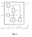
- Fig. 1 very diagrammatically shows a system according to the invention.
- the system 1 comprises a housing 10 with a first image sensor 12, a second image sensor 14 with an adjustable lens 16, a control unit 18, a hair-removing device 20 and an optical coupling 22.
- the separate movable lens 16 as well as the optical coupling 22 are optional, as will be explained further on.
- the housing 10 of the system 1 as shown only comprises parts that are relevant for the present invention. Obviously, additional parts, such as a power unit, an optical window etc, may be present, but are not shown.
- the first image sensor 12 may comprise, e.g., a CCD camera, a CMOS device etc.
- the second image sensor 14 is coupled to an adjustable lens 16, and may comprise a scanning unit.
- Both image sensors 12 and 14 are coupled to a control unit 18, that is constructed and arranged to discern hairs from the image as obtained by the sensors 12 and 14.
- a hair-removing device such as a laser system, an electrical epilating system etc.
- the lens 16 may be moved in the direction of arrow A, to focus at different values of z, in order to scan and produce an image in the z-dimension.
- the adjustable lens 16 may be moved aside in the direction, e.g., perpendicular to arrow A in order to free a field of view of the first image sensor 12.
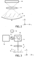
- Fig. 2 very diagrammatically shows a first image sensor as used in the system according to the invention.
- 40 denotes a CCD
- 42 denotes an optical system
- 44 denotes a field of view of the CCD.
- more than one hair is present in the field of view of the CCD, as most CCDs have fields of view of, e.g., one or more cm 2 .
- Such an area of, e.g., a human beard contains several dozens of hairs.
- the resolution, and the range in the perpendicular direction, for example the Z direction as shown in the Figure is very limited and determined by the properties of the optical system 42. Note that a CCD can determine an image in one step, all the pixels being "filled" simultaneously.
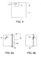
- Fig. 3 very diagrammatically shows a second image sensor that may be used in the system according to the invention.
- 50 denotes a laser source
- 51 denotes a beam splitter
- 52 denotes a beam manipulator with a movable mirror 54 that is movable, e.g., in the direction of arrow B.
- a detector is denoted by means of reference numeral 56, while a lens 58 is movable in the direction of arrow C.
- any other suitable radiation source may be selected, such as a LED with a lens.
- the emitted beam is partly transmitted by beam splitter 51 (which may or may not be polarizing), and partly reflected downwards, e.g., to a beam dump (not shown).
- Beam manipulator 52 is, e.g., controllable by the control unit (not shown), and comprises a movable mirror 54, such as a polygon mirror or any other suitable type of scan mirror.
- the mirror 54 is movable, e.g. rotatable, in the direction of arrow B, in order to scan a beam of radiation across a desired area, in this case a second field -of view.
- the field of view of the second image sensor will have dimensions of about 0.5 mm x 0.5 mm in the x, y directions, and a similar dimension in the z direction.
- the optical system or lens 58 is movable in the direction C.
- the optical system or lens 58 may be adjustable in optical power, i.e. the focal length thereof.
- the detector 56 is optically coupled to the beam manipulator 52 via the beam splitter 51. Radiation that is reflected, Raman-scattered etc., at the skin 30 or hairs 32, is reflected by the mirror 54 towards beam splitter 51, and will be partly reflected towards detector 56.
- the detector 56 may comprise a CCD or CMOS, or any other kind of photodetector or array thereof.
- the detector 56 will also be coupled to the control unit (not shown) in order for the control unit to determine the position and/or orientation of a hair 32 on a skin 30.
- the control unit for this second image sensor, a three-dimensional image will be obtained.
- This type of image sensor may also be referred to as a 3D scanning sensor. As it is known per se in the state of the art, further details will be omitted, but will be apparent to the skilled person.
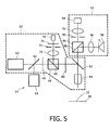
- Fig. 4 diagrammatically indicates fields of view of the first and second image sensor, including one hair on skin.
- the area indicated by I is a square of about 2 x 2 mm. It is about 1/100 th of the surface area of an average field of view of a CCD sensor as suggested by the dashed line III.
- the area I of 2 x 2 mm represents the average surface area per hair 32 of a human beard.
- the hair 32 has been drawn to scale, albeit diagrammatically, having a diameter of about 120 micrometer.
- a surface area denoted by II This denotes an average surface area as may be scanned by a present day 3D scanner sensor. Its dimensions are about 0.5 x 0.5 (x 0.5) mm.
- Fig. 5 diagrammatically shows a hair-removal system according to the present invention in more detail.
- S1 generally denotes a first image sensor
- S2 denotes a second image sensor
- S3 denotes a hair-removal system.
- the second image sensor S2 comprises a detection laser 60, a beam splitter 62, a shutter 66, a first polarizing beam splitter 68 with a first beam splitting surface 69, a first lens 70, a first pinhole 72, a bandpass filter 74 and a detector 76. Furthermore, it comprises a ⁇ /4 plate 80, a mirror 82, and an object lens 84.
- the first image sensor S1 generally comprises a second polarizing beam splitter 86 with a second beam splitting surface 88, a diaphragm 90, a tube lens 92 and a CCD 94, as well as a LED lens 96, and a LED 98.
- the hair-removing device comprises a cutting laser 64.
- the cutting laser 64, as well as the detection laser 60, the detector 76 and the CCD 94 and the object lens 84 may all be connected to a control unit (not shown).
- the detection laser 60 and the cutting laser 64 may also be one and the same laser, especially if this is an adjustable laser.
- various parts are optional, such as, in the latter case, beam splitter 62, shutter 66, polarizing beam splitters 68 and 86, pinholes 72 and 90, ⁇ /4 plate 80 and mirror 82.
- light for the CCD detection method of the first image sensor S1 is emitted by the LED 98 with optional LED lens 96.
- Part of the radiation is reflected by the surface 88, passes the mirror 82 which is transparent to LED radiation but highly reflective to, in this case, e.g., 1064 nm radiation, and strikes the skin 30 with a hair 32.
- An image thereof is reflected and again passes the second polarizing beam splitter 86, the pinhole 90, the tube lens 92, and is detected by the CCD 94.
- the object lens 84 may be movable, and may be moved out of the way.
- light or other radiation such as infrared radiation, may also be supplied directly, i.e. not confocally. For example, a LED might shine directly onto the skin. In such cases, a beam splitter 86 would not be required.
- Figs. 6A and 6B show two steps of a method of determining a hair position and cutting the hair.
- II shows an image of a part of the skin, with one hair 32 present.
- 100 denotes a guiding rail and 102 denotes a movable lens.
- the complete system will be moved across the skin. Since movement is relative, this is shown in Fig. 6A as a hair 32 moving with a velocity v in the direction of the arrow as shown.
- the rough position of the hair 32 in x and y is determined.
- the movable lens 102 is moved along the guiding rail 100 to this x,y position, see Figure 6B , where the z-position is determined by scanning.
- the hair may be removed, by firing a laser, electrical epilating through appropriate positioning of electric needles, etc.
- a numerical example may be as follows. An average velocity when shaving is about 5 cm/s. A useful resolution in x, y is about 20 micrometer. With a common 1000 x 1000 pixel camera, this would result in a total field of 2 cm x 2 cm. This in turn results in a frame rate of the camera of 2.5 kHz, or an acquisition time of 0.4 ms. This can easily be obtained with a CMOS system.
- the movable lens 102 may, for example, be the lens of a DVD sled, which has a typical access time of 15 ms (66 Hz). While a DVD actuator unit has a resolution of about 20 nm, only about 20 ⁇ m resolution is needed.
- the actuator for the movable lens can move the lens along the y,z direction over 1-2 mm with 5-6 kHz (0.16-0.20 ms). Once the movable lens is set to the proper position, the actuator, with the lens, can scan locally in a 3D method as explained earlier. In the correct position, again, the hair may be removed with any suitable technique.
- a limiting time of the above embodiment is the access time of the movable lens, which is approximately 15 ms. For a typical human beard having about 12.000 hairs, this would result in a shaving time of about 3 minutes, which is a normal time for a shave.
- 110 is an image sensor (e.g., CCD/CMOS), a first, second and third movable lens array are denoted by 112, 114, and 122, respectively.
- 116 is a polarizing beam splitter, 118 is a ring light aperture, 120 is a lens.
- 30 denotes skin with a hair 32.
- a first imaging step is depicted.
- the apertures of the third lens array 122 are projected by lens 120 onto the apertures of the second lens array 114, which in turn are projected onto the apertures of the first lens array 112, which in turn are projected on the image sensor 110.
- the image of the object in this case skin 30, is projected on the image sensor 110 such that the individual lens images are not each mirrored. Every lens produces a small part of a larger image of the object.
- this lens 120 projects the light-emitting ring light aperture 118 on the third lens array 122.
- these lens arrays are each subjected to a substantially identical continuous motion in a harmonious fashion, e.g. rotational or vibrational, in the plane of the image sensor 110.
- the whole system is moved laterally over the skin 30 by the user of the system, to perform the shaving action.
- each lens of the three lens arrays that constitute a single facet of the imaging system generates a projection of the region of interest, or field of view, on the image sensor 110 in a repetitive manner.
- every point on the object 30, 32, within the field of view of the third lens array 122 is preferably, but not exclusively, imaged with such a frequency that the lateral displacement from scan to scan due to the user's lateral motion is roughly equivalent to, and not much more than, the intended lateral target resolution of, say, 20 ⁇ m.
- the sensor 110 is undergoing the same lateral displacement as the lens arrays, but not the harmonic motion.
- the image of the object 30, 32, as projected on the sensor 110 moves at the same lateral speed as the lenses of the lens arrays and image sensor combination, while the harmonic (rotating, vibrating,%) motion is only experienced by the lens arrays 112, 114, 122.
- the lens 120 serves to project the apertures of the third lens array 122 onto those of the second lens array 114.
- a considerable amount of space is made available on either side of the lens 120, which space can be used for the second stage of the detection process, to be discussed later, and for coupling in light that is needed for the image formation.
- the polarizing beam splitter 116 For this latter purpose, use is made in this case of the polarizing beam splitter 116.
- the required resolution is 20 ⁇ m, although of course other values may also be taken.
- the speed at which the user moves the system over the skin is taken to be at most 5 cm/s. Again, for other cases, these values may be adapted, causing corresponding changes to the following figures.
- the lens arrays consist of a disc of about 2 cm diameter with a number of 2 mm aperture lenses regularly spaced around the circumference, see Fig. 8 . Although 16 lenses are shown, it is assumed in this numerical example that 25 lenses are present.
- the 2D image is recorded by means of the image sensor 110, such as a CCD or CMOS imaging sensor, preferably at the same refresh rate (2.5 kHz) so that only very minor motional blurring will occur. Furthermore, to ensure that a surface area of 2 x 2 cm will be imaged with a resolution of 20 ⁇ m, at least 1000 x 1000 pixels are required. Both this number and the required refresh rate are easily achievable with today's CCD and CMOS technology. It will be clear that other shapes of and values for the disc, number and aperture of lenses et cetera, are possible, which will require an adaptation of the other figures.
- the above imaging is a first step in the total imaging process according to the invention, in which a 2D image is obtained. Note that a resolution of 20 ⁇ m or similar is not yet required at this stage. A lower resolution may be selected, with a reduced acquisition time, as long as an approximate target position can be obtained. A more exact position, with the desired resolution, may be obtained in the second stage of the imaging, i.e. with the second image sensor.
- the presence of a specific target is either detected at a specific and fixed depth (or z-position), or scanned in order to determine its position and orientation in space.
- a specific target such as a hair
- the first option is selected, e.g., in order to shave hairs off at a certain length .
- the presence of the target at the specified depth is determined, e.g., by means of cross-polarized confocal laser scanning.
- a laser beam is aimed through a selected lens of the third lens array 122. This selected lens will focus the laser beam in a point that is moving parallel to the moving lens, i.e.
- the lens will collimate light that is reflected back from the focal volume.
- a second, neighboring lens will enter the laser beam and perform a new scan.
- the lateral resolution of the detection is dictated by the resolution of the confocal scan, and the distance between consecutive scans is determined by the speed at which the system as a whole moves over the target area of the skin.
- the intensity of the reflection of the orthogonally polarized light that is reflected or scattered back from the target area is confocally detected by means of the polarizing beam splitter 116 and a lens-pinhole combination, not shown here, but cf. Fig. 5 .
- the amount of light captured by the detector may provide information on the presence of various structures in the focal area (field -of view) and thereby ascertain the 3D position and/or orientation thereof.
- the system could function as follows.
- the first imaging sensor detects an image of skin with hair
- the control unit not shown but either on-chip (CMOS) or as a separate module, determines an approximate position of the hair(s) on the skin.
- the accuracy may, e.g., be about 100 or 200 ⁇ m.
- the control unit can aim a detection laser, e.g., by means of a deflection unit (not shown but cf. 52, 54 of Fig.
- a MOEMS micro-optical-electrical mechanical system
- a dichroic mirror between the third rotating lens array 122 and the lens 120, towards the position on the rotating lens array where the hair was approximately found.
- the control unit records the results from the confocal laser scan, and interprets the results, i.e. the second imaging step.
- the detection system enables the cutting laser, which emits continuous or pulsed laser radiation that is coupled into the lens collinearly or at a known angle and thus is focused at the original detection laser focus spot or at a known distance from that focus, respectively. The radiation from the cutting laser then cuts the hair.
- the detection laser beam passes only one lens of the lens array(s) at a time; in other words, the laser beam diameter is preferably smaller than the lens pitch to avoid ambiguous detection results.
- the shape of the disk 130, the number, pitch and size of the lenses 132, their motion etc. may all be varied in the method, as long as required corresponding quantities etc., are also adapted. Even more explicitly, the above-described example only serves to show the applicability of the proposed invention. Furthermore, in all of the above, a preferred method of removing hairs was cutting them with a laser beam.
- the invention provides a system and method to reduce that time by providing a rough pre-imaging step and a second imaging step to find the three dimensions of the position with the required precision.
- the final 3D position may be found by taking the first two coordinates of the first imaging step, and adding a third coordinate in the second imaging step, or all three coordinates may be determined in the second step, after a first rough estimate in the first 2D step, etcetera.
Landscapes
- Physics & Mathematics (AREA)
- Health & Medical Sciences (AREA)
- Surgery (AREA)
- Optics & Photonics (AREA)
- Life Sciences & Earth Sciences (AREA)
- Heart & Thoracic Surgery (AREA)
- General Health & Medical Sciences (AREA)
- Nuclear Medicine, Radiotherapy & Molecular Imaging (AREA)
- Engineering & Computer Science (AREA)
- Biomedical Technology (AREA)
- Electromagnetism (AREA)
- Medical Informatics (AREA)
- Molecular Biology (AREA)
- Animal Behavior & Ethology (AREA)
- Otolaryngology (AREA)
- Public Health (AREA)
- Veterinary Medicine (AREA)
- Measurement Of The Respiration, Hearing Ability, Form, And Blood Characteristics Of Living Organisms (AREA)
- Length Measuring Devices By Optical Means (AREA)
- Image Input (AREA)
- Laser Surgery Devices (AREA)
- Radiation-Therapy Devices (AREA)
- Thermotherapy And Cooling Therapy Devices (AREA)
Claims (14)
- Haarentfernungssystem mit:einer Haarerfassungseinrichtung (S1, S2) sowieeiner Haarentfernungseinrichtung (20; S3), die mit der Haarerfassungseinrichtung betriebsbereit gekoppelt ist,wobei die Haarerfassungseinrichtung umfasst:dadurch gekennzeichnet, dass die Abbildungseinrichtung einen zweiten Bildsensor (14; S2) umfasst, der sich von dem ersten Bildsensor (12; S1) unterscheidet, wobei der zweite Bildsensor (14; S2) so eingerichtet ist, dass er einen ausgewählten Teil des Teils der Haut (30) abbildet, der von dem ersten Bildsensor (12; S1) abgebildet wird, und wobei der zweite Bildsensor imstande ist, in den jeweiligen Abbildungen eine höhere räumliche Informationsdichte als der erste Bildsensor vorzusehen.- eine Abbildungseinrichtung mit einem ersten Bildsensor (12; S1), der so konstruiert und eingerichtet ist, dass er eine Abbildung eines zu behandelnden Teils einer Haut (30) erfasst, wobei die Abbildungseinrichtung einen zweiten Bildsensor (14; S2) umfasst, der sich von dem ersten Bildsensor (12; S1) unterscheidet, und- eine Steuereinheit (18), die so konstruiert und eingerichtet ist, dass sie in der Abbildung ein Haar (32) auf dem Teil der Haut (30) erkennt, und die mit der Haarentfernungseinrichtung (20; S3) zur Steuerung des Betriebs derselben betriebsbereit gekoppelt ist,
- Haarentfernungssystem nach Anspruch 1, wobei der erste Bildsensor (12; S1) so konstruiert ist, dass er eine im Wesentlichen zweidimensionale Abbildung vorsieht.
- Haarentfernungssystem nach Anspruch 1, wobei der erste Bildsensor (12; S1) einen optischen 2D-Bildsensor, vorzugsweise eine ladungsgekoppelte Einrichtung, eine CMOS-Einrichtung oder ein Focal-Plane-Array aus Photodetektoren, umfasst.
- Haarentfernungssystem nach Anspruch 1, wobei der erste Bildsensor (12; S1) so konstruiert ist, dass er eine Abbildung eines Teils der Haut (30) von mindestens 2 mm x 2 mm, vorzugsweise mindestens 1 cm x 1 cm, detektiert.
- Haarentfernungssystem nach Anspruch 1, wobei zumindest ein Teil des zweiten Bildsensors (14; S2) gegenüber dem ersten Bildsensor (12; S1) bewegbar ist.
- Haarentfernungssystem nach Anspruch 1, wobei der zweite Bildsensor (14; S2) in mindestens einer Dimension eine höhere Auflösung als eine Auflösung des ersten Bildsensors (12; S1) in dieser Dimension aufweist.
- Haarentfernungssystem nach Anspruch 2, wobei der zweite Bildsensor (14; S2) so konstruiert ist, dass er einen ausgewählten Teil des zu behandelnden Teils der Haut (30) abtastet, um damit eine Abbildung desselben in einer dritten Dimension außerhalb der zweidimensionalen Abbildung des ersten Bildsensors vorzusehen.
- Haarentfernungssystem nach Anspruch 1, wobei der zweite Bildsensor (14; S2) einen 3D-Bildsensor, insbesondere einen optischen 3D-Bildsensor mit einer einstellbaren Linse (16; 58; 84), umfasst, der vorzugsweise in einer Richtung senkrecht zu dem zu behandelnden Teil der Haut (30) bewegbar ist.
- Haarentfernungssystem nach Anspruch 8, wobei die Linse (16; 58; 84) in einer Richtung bewegbar ist, die im Wesentlichen parallel zu dem zu behandelnden Teil der Haut (30) verläuft.
- Haarentfernungssystem nach Anspruch 1, welches weiterhin eine Lichtquelle (50; 60; 98) umfasst.
- Haarentfernungssystem nach Anspruch 10, wobei es sich bei der Lichtquelle um eine LED (98) oder eine Laserquelle (50; 60) handelt.
- Haarentfernungssystem nach Anspruch 11, wobei die Laserquelle (50; 60) eine einstellbare Laserquelle ist.
- Haarentfernungssystem nach Anspruch 12, wobei die Laserquelle (50; 60) zwischen einem ersten Leistungsniveau, das eine Detektion ohne wesentlichen Schaden an der Haut (30) und/oder dem Haar (32) ermöglicht, und einem zweiten Leistungsniveau, mit dem das Haar (32) für das danach zu entfernende Haar (32) hinreichend beschädigt werden kann, einstellbar ist.
- Haarentfernungssystem nach Anspruch 12, wobei das System Strahlbreitenregelungsmittel (16; 58; 84) umfasst.
Priority Applications (1)
| Application Number | Priority Date | Filing Date | Title |
|---|---|---|---|
| EP06780157A EP1909680B1 (de) | 2005-07-26 | 2006-07-21 | Haarentfernungssystem |
Applications Claiming Priority (3)
| Application Number | Priority Date | Filing Date | Title |
|---|---|---|---|
| EP05106845 | 2005-07-26 | ||
| PCT/IB2006/052500 WO2007013008A1 (en) | 2005-07-26 | 2006-07-21 | Hair removing system |
| EP06780157A EP1909680B1 (de) | 2005-07-26 | 2006-07-21 | Haarentfernungssystem |
Publications (2)
| Publication Number | Publication Date |
|---|---|
| EP1909680A1 EP1909680A1 (de) | 2008-04-16 |
| EP1909680B1 true EP1909680B1 (de) | 2011-03-02 |
Family
ID=37461548
Family Applications (1)
| Application Number | Title | Priority Date | Filing Date |
|---|---|---|---|
| EP06780157A Not-in-force EP1909680B1 (de) | 2005-07-26 | 2006-07-21 | Haarentfernungssystem |
Country Status (8)
| Country | Link |
|---|---|
| US (1) | US9283038B2 (de) |
| EP (1) | EP1909680B1 (de) |
| JP (1) | JP5094719B2 (de) |
| CN (1) | CN101232853B (de) |
| AT (1) | ATE499893T1 (de) |
| DE (1) | DE602006020452D1 (de) |
| ES (1) | ES2362117T3 (de) |
| WO (1) | WO2007013008A1 (de) |
Cited By (1)
| Publication number | Priority date | Publication date | Assignee | Title |
|---|---|---|---|---|
| EP4164534A1 (de) * | 2020-06-12 | 2023-04-19 | Koninklijke Philips N.V. | System und verfahren zur bestimmung des hautkontakts für eine körperpflegevorrichtung |
Families Citing this family (29)
| Publication number | Priority date | Publication date | Assignee | Title |
|---|---|---|---|---|
| AU2003245573A1 (en) | 2002-06-19 | 2004-01-06 | Palomar Medical Technologies, Inc. | Method and apparatus for treatment of cutaneous and subcutaneous conditions |
| US7856985B2 (en) | 2005-04-22 | 2010-12-28 | Cynosure, Inc. | Method of treatment body tissue using a non-uniform laser beam |
| US7586957B2 (en) | 2006-08-02 | 2009-09-08 | Cynosure, Inc | Picosecond laser apparatus and methods for its operation and use |
| EP2106823A4 (de) * | 2007-01-26 | 2010-10-27 | Panasonic Elec Works Co Ltd | Vorrichtung zur regulierung des sichtbaren körperhaarwachstums |
| US20080262484A1 (en) * | 2007-04-23 | 2008-10-23 | Nlight Photonics Corporation | Motion-controlled laser surface treatment apparatus |
| RU2497478C2 (ru) * | 2008-03-21 | 2013-11-10 | Конинклейке Филипс Электроникс Н.В. | Система и способ для удаления волос |
| US20100186234A1 (en) | 2009-01-28 | 2010-07-29 | Yehuda Binder | Electric shaver with imaging capability |
| WO2010143108A2 (en) * | 2009-06-11 | 2010-12-16 | Koninklijke Philips Electronics N.V. | Optical scanner |
| US20110194762A1 (en) * | 2010-02-04 | 2011-08-11 | Samsung Electronics Co., Ltd. | Method for detecting hair region |
| RU2559306C2 (ru) * | 2010-04-01 | 2015-08-10 | Конинклейке Филипс Электроникс Н.В. | Лазерная сканирующая система, устройство для стрижки волос и соответствующий способ |
| CN103619209B (zh) * | 2011-06-22 | 2016-05-18 | 莱蒂恩思公司 | 毛发去除和再生抑制装置 |
| RU2620317C2 (ru) * | 2011-12-27 | 2017-05-24 | Конинклейке Филипс Н.В. | Электробритва |
| WO2013158299A1 (en) | 2012-04-18 | 2013-10-24 | Cynosure, Inc. | Picosecond laser apparatus and methods for treating target tissues with same |
| BR112014028805A2 (pt) * | 2012-05-22 | 2017-06-27 | Koninklijke Philips Nv | cabeça de corte para um dispositivo de corte de pelos, dispositivo para corte de pelos e método para controlar um dispositivo de corte de pelos |
| US9676059B2 (en) * | 2012-07-31 | 2017-06-13 | Koninklijke Philips N.V. | Laser hair cutter |
| US20140074133A1 (en) * | 2012-09-10 | 2014-03-13 | Palomar Medical Technologies, Inc. | Combination of shaver and opto-thermal modification of hair |
| EP2973894A2 (de) | 2013-03-15 | 2016-01-20 | Cynosure, Inc. | Optische picosekunden-strahlungssysteme und verfahren zur verwendung |
| EP3013213B1 (de) * | 2013-06-25 | 2020-09-23 | Koninklijke Philips N.V. | Messungsvorrichtung für hauteigenschaften und nicht-invasive behandlungsvorrichtung |
| KR101426539B1 (ko) * | 2014-04-22 | 2014-08-13 | (주)하배런메디엔뷰티 | 작동 안전성이 향상된 제모기 |
| JP6684726B2 (ja) * | 2014-07-25 | 2020-04-22 | コーニンクレッカ フィリップス エヌ ヴェKoninklijke Philips N.V. | 毛を切断するための装置 |
| CN106572885B (zh) * | 2014-07-25 | 2019-09-03 | 皇家飞利浦有限公司 | 用于切割毛发的装置 |
| EP3232856B1 (de) * | 2014-12-18 | 2018-06-06 | Koninklijke Philips N.V. | Haarentfernungsvorrichtung |
| MX2018005143A (es) * | 2015-10-30 | 2018-06-06 | Unilever Nv | Medicion de rizo del cabello. |
| WO2017215609A1 (en) * | 2016-06-15 | 2017-12-21 | Hong Kong Health And Beauty Limited | Devices and methods to remove hair |
| CN106175928A (zh) * | 2016-07-14 | 2016-12-07 | 华北电力大学 | 一种激光精确定位的医疗系统及定位方法 |
| US20180360527A1 (en) * | 2017-06-15 | 2018-12-20 | Sciton, Inc. | Methods and systems for hair treatment |
| CN207689764U (zh) * | 2018-01-29 | 2018-08-03 | 李明 | 激光剃须装置 |
| CN112042066A (zh) | 2018-02-26 | 2020-12-04 | 赛诺秀股份有限公司 | 调q倾腔亚纳秒激光器 |
| CN121370364B (zh) * | 2025-12-24 | 2026-03-31 | 苏州芙迈蕾医疗科技有限公司 | 强脉冲光治疗手具的出光控制方法、装置及存储介质 |
Family Cites Families (13)
| Publication number | Priority date | Publication date | Assignee | Title |
|---|---|---|---|---|
| JPH06223277A (ja) * | 1993-01-21 | 1994-08-12 | Ibiden Co Ltd | セキュリティシステム |
| EG20471A (en) | 1993-07-12 | 1999-05-31 | Thermotrex Corp | Hair removal device and method |
| JPH0850696A (ja) * | 1994-08-05 | 1996-02-20 | Nippondenso Co Ltd | 走行車両のナンバー認識装置 |
| US6149645A (en) * | 1998-04-03 | 2000-11-21 | Tobinick; Edward L. | Apparatus and method employing lasers for removal of hair |
| CN1213097A (zh) * | 1998-10-29 | 1999-04-07 | 厦门大学 | 制作医学影像诊断用的断层组合三维全息显示装置 |
| JP3921306B2 (ja) * | 1999-02-26 | 2007-05-30 | 株式会社ニデック | レーザ治療装置 |
| DE60023236T2 (de) | 1999-04-14 | 2007-01-11 | Koninklijke Philips Electronics N.V. | Einrichtung zur haarentfernung mit einer steuerbaren laserquelle |
| JP2002000745A (ja) | 2000-06-16 | 2002-01-08 | Nidek Co Ltd | レーザ治療装置 |
| EP1372486A2 (de) | 2001-03-09 | 2004-01-02 | Lucid, Inc. | System und verfahren für die makroskopische und konfokale bilddarstellung von gewebe |
| US7217266B2 (en) | 2001-05-30 | 2007-05-15 | Anderson R Rox | Apparatus and method for laser treatment with spectroscopic feedback |
| WO2003074967A1 (fr) * | 2002-03-07 | 2003-09-12 | Takaoka Electric Mfg.Co., Ltd. | Detecteur a synchronisation de photo-reception bidimensionnelle du type a detection d'angle de polarisation, et dispositif de mesure de forme superficielle l'utilisant |
| US7627363B2 (en) | 2003-03-18 | 2009-12-01 | The General Hospital Corporation | Polarized light imaging devices and methods |
| ES2375609T3 (es) | 2003-08-04 | 2012-03-02 | Koninklijke Philips Electronics N.V. | Dispositivo para acortar cabellos por medio de efectos de ruptura óptica inducida por l�?ser. |
-
2006
- 2006-07-21 ES ES06780157T patent/ES2362117T3/es active Active
- 2006-07-21 DE DE602006020452T patent/DE602006020452D1/de active Active
- 2006-07-21 JP JP2008523507A patent/JP5094719B2/ja not_active Expired - Fee Related
- 2006-07-21 CN CN200680027289XA patent/CN101232853B/zh not_active Expired - Fee Related
- 2006-07-21 EP EP06780157A patent/EP1909680B1/de not_active Not-in-force
- 2006-07-21 US US11/996,318 patent/US9283038B2/en not_active Expired - Fee Related
- 2006-07-21 AT AT06780157T patent/ATE499893T1/de not_active IP Right Cessation
- 2006-07-21 WO PCT/IB2006/052500 patent/WO2007013008A1/en not_active Ceased
Cited By (1)
| Publication number | Priority date | Publication date | Assignee | Title |
|---|---|---|---|---|
| EP4164534A1 (de) * | 2020-06-12 | 2023-04-19 | Koninklijke Philips N.V. | System und verfahren zur bestimmung des hautkontakts für eine körperpflegevorrichtung |
Also Published As
| Publication number | Publication date |
|---|---|
| ES2362117T3 (es) | 2011-06-28 |
| CN101232853B (zh) | 2010-09-29 |
| CN101232853A (zh) | 2008-07-30 |
| US9283038B2 (en) | 2016-03-15 |
| EP1909680A1 (de) | 2008-04-16 |
| ATE499893T1 (de) | 2011-03-15 |
| JP5094719B2 (ja) | 2012-12-12 |
| DE602006020452D1 (de) | 2011-04-14 |
| JP2009502295A (ja) | 2009-01-29 |
| WO2007013008A1 (en) | 2007-02-01 |
| US20080215038A1 (en) | 2008-09-04 |
Similar Documents
| Publication | Publication Date | Title |
|---|---|---|
| EP1909680B1 (de) | Haarentfernungssystem | |
| US8784407B2 (en) | Hair removal system and method | |
| JP4672260B2 (ja) | 画像装置 | |
| US12105271B2 (en) | Microscope and method for microscopic image recording with variable illumination | |
| JP5897563B2 (ja) | ライン走査式顕微鏡における同期用システム | |
| JP6914241B2 (ja) | 3次元イメージングのためのシステムおよび方法 | |
| US7101365B1 (en) | Laser for skin treatment | |
| JP4202136B2 (ja) | 組成分析 | |
| CN102928970B (zh) | 一种大样本快速三维显微成像的方法和系统 | |
| WO2010126790A1 (en) | A novel multi-point scan architecture | |
| JP2008272489A (ja) | 眼底カメラ | |
| JP2021089430A (ja) | 操作された励起放射線によって複数の試料を撮像する方法および装置 | |
| JP5131552B2 (ja) | 顕微鏡装置 | |
| US20060256194A1 (en) | Parallel confocal laser microscopy system based on vcsel technology | |
| CN115813546A (zh) | 一种激光出射装置及激光美容仪 | |
| CN109978932B (zh) | 利用结构光获取检测对象的深度信息的系统和方法 | |
| US12619057B2 (en) | Light-field microscopy image capturing method and light-field microscope | |
| US20230324661A1 (en) | Light-field microscopy image capturing method and light-field microscope | |
| JP2006087839A (ja) | 光脱毛装置 | |
| CN119309511A (zh) | 一种三维扫描激光作用装置及系统 | |
| WO2015114631A1 (en) | Detecting and treating skin surface features |
Legal Events
| Date | Code | Title | Description |
|---|---|---|---|
| PUAI | Public reference made under article 153(3) epc to a published international application that has entered the european phase |
Free format text: ORIGINAL CODE: 0009012 |
|
| 17P | Request for examination filed |
Effective date: 20080226 |
|
| AK | Designated contracting states |
Kind code of ref document: A1 Designated state(s): AT BE BG CH CY CZ DE DK EE ES FI FR GB GR HU IE IS IT LI LT LU LV MC NL PL PT RO SE SI SK TR |
|
| 17Q | First examination report despatched |
Effective date: 20100126 |
|
| GRAP | Despatch of communication of intention to grant a patent |
Free format text: ORIGINAL CODE: EPIDOSNIGR1 |
|
| DAX | Request for extension of the european patent (deleted) | ||
| GRAS | Grant fee paid |
Free format text: ORIGINAL CODE: EPIDOSNIGR3 |
|
| GRAA | (expected) grant |
Free format text: ORIGINAL CODE: 0009210 |
|
| AK | Designated contracting states |
Kind code of ref document: B1 Designated state(s): AT BE BG CH CY CZ DE DK EE ES FI FR GB GR HU IE IS IT LI LT LU LV MC NL PL PT RO SE SI SK TR |
|
| REG | Reference to a national code |
Ref country code: GB Ref legal event code: FG4D |
|
| REG | Reference to a national code |
Ref country code: CH Ref legal event code: EP |
|
| REG | Reference to a national code |
Ref country code: IE Ref legal event code: FG4D |
|
| REF | Corresponds to: |
Ref document number: 602006020452 Country of ref document: DE Date of ref document: 20110414 Kind code of ref document: P |
|
| REG | Reference to a national code |
Ref country code: DE Ref legal event code: R096 Ref document number: 602006020452 Country of ref document: DE Effective date: 20110414 |
|
| REG | Reference to a national code |
Ref country code: NL Ref legal event code: T3 |
|
| REG | Reference to a national code |
Ref country code: SE Ref legal event code: TRGR |
|
| REG | Reference to a national code |
Ref country code: ES Ref legal event code: FG2A Ref document number: 2362117 Country of ref document: ES Kind code of ref document: T3 Effective date: 20110628 |
|
| PG25 | Lapsed in a contracting state [announced via postgrant information from national office to epo] |
Ref country code: GR Free format text: LAPSE BECAUSE OF FAILURE TO SUBMIT A TRANSLATION OF THE DESCRIPTION OR TO PAY THE FEE WITHIN THE PRESCRIBED TIME-LIMIT Effective date: 20110603 Ref country code: LT Free format text: LAPSE BECAUSE OF FAILURE TO SUBMIT A TRANSLATION OF THE DESCRIPTION OR TO PAY THE FEE WITHIN THE PRESCRIBED TIME-LIMIT Effective date: 20110302 Ref country code: LV Free format text: LAPSE BECAUSE OF FAILURE TO SUBMIT A TRANSLATION OF THE DESCRIPTION OR TO PAY THE FEE WITHIN THE PRESCRIBED TIME-LIMIT Effective date: 20110302 |
|
| LTIE | Lt: invalidation of european patent or patent extension |
Effective date: 20110302 |
|
| PG25 | Lapsed in a contracting state [announced via postgrant information from national office to epo] |
Ref country code: FI Free format text: LAPSE BECAUSE OF FAILURE TO SUBMIT A TRANSLATION OF THE DESCRIPTION OR TO PAY THE FEE WITHIN THE PRESCRIBED TIME-LIMIT Effective date: 20110302 Ref country code: BG Free format text: LAPSE BECAUSE OF FAILURE TO SUBMIT A TRANSLATION OF THE DESCRIPTION OR TO PAY THE FEE WITHIN THE PRESCRIBED TIME-LIMIT Effective date: 20110602 Ref country code: SI Free format text: LAPSE BECAUSE OF FAILURE TO SUBMIT A TRANSLATION OF THE DESCRIPTION OR TO PAY THE FEE WITHIN THE PRESCRIBED TIME-LIMIT Effective date: 20110302 Ref country code: CY Free format text: LAPSE BECAUSE OF FAILURE TO SUBMIT A TRANSLATION OF THE DESCRIPTION OR TO PAY THE FEE WITHIN THE PRESCRIBED TIME-LIMIT Effective date: 20110302 Ref country code: AT Free format text: LAPSE BECAUSE OF FAILURE TO SUBMIT A TRANSLATION OF THE DESCRIPTION OR TO PAY THE FEE WITHIN THE PRESCRIBED TIME-LIMIT Effective date: 20110302 |
|
| PG25 | Lapsed in a contracting state [announced via postgrant information from national office to epo] |
Ref country code: BE Free format text: LAPSE BECAUSE OF FAILURE TO SUBMIT A TRANSLATION OF THE DESCRIPTION OR TO PAY THE FEE WITHIN THE PRESCRIBED TIME-LIMIT Effective date: 20110302 |
|
| PG25 | Lapsed in a contracting state [announced via postgrant information from national office to epo] |
Ref country code: EE Free format text: LAPSE BECAUSE OF FAILURE TO SUBMIT A TRANSLATION OF THE DESCRIPTION OR TO PAY THE FEE WITHIN THE PRESCRIBED TIME-LIMIT Effective date: 20110302 Ref country code: PT Free format text: LAPSE BECAUSE OF FAILURE TO SUBMIT A TRANSLATION OF THE DESCRIPTION OR TO PAY THE FEE WITHIN THE PRESCRIBED TIME-LIMIT Effective date: 20110704 |
|
| PG25 | Lapsed in a contracting state [announced via postgrant information from national office to epo] |
Ref country code: CZ Free format text: LAPSE BECAUSE OF FAILURE TO SUBMIT A TRANSLATION OF THE DESCRIPTION OR TO PAY THE FEE WITHIN THE PRESCRIBED TIME-LIMIT Effective date: 20110302 Ref country code: SK Free format text: LAPSE BECAUSE OF FAILURE TO SUBMIT A TRANSLATION OF THE DESCRIPTION OR TO PAY THE FEE WITHIN THE PRESCRIBED TIME-LIMIT Effective date: 20110302 Ref country code: IS Free format text: LAPSE BECAUSE OF FAILURE TO SUBMIT A TRANSLATION OF THE DESCRIPTION OR TO PAY THE FEE WITHIN THE PRESCRIBED TIME-LIMIT Effective date: 20110702 Ref country code: RO Free format text: LAPSE BECAUSE OF FAILURE TO SUBMIT A TRANSLATION OF THE DESCRIPTION OR TO PAY THE FEE WITHIN THE PRESCRIBED TIME-LIMIT Effective date: 20110302 |
|
| PLBE | No opposition filed within time limit |
Free format text: ORIGINAL CODE: 0009261 |
|
| STAA | Information on the status of an ep patent application or granted ep patent |
Free format text: STATUS: NO OPPOSITION FILED WITHIN TIME LIMIT |
|
| 26N | No opposition filed |
Effective date: 20111205 |
|
| PG25 | Lapsed in a contracting state [announced via postgrant information from national office to epo] |
Ref country code: DK Free format text: LAPSE BECAUSE OF FAILURE TO SUBMIT A TRANSLATION OF THE DESCRIPTION OR TO PAY THE FEE WITHIN THE PRESCRIBED TIME-LIMIT Effective date: 20110302 Ref country code: PL Free format text: LAPSE BECAUSE OF FAILURE TO SUBMIT A TRANSLATION OF THE DESCRIPTION OR TO PAY THE FEE WITHIN THE PRESCRIBED TIME-LIMIT Effective date: 20110302 Ref country code: MC Free format text: LAPSE BECAUSE OF NON-PAYMENT OF DUE FEES Effective date: 20110731 |
|
| REG | Reference to a national code |
Ref country code: CH Ref legal event code: PL |
|
| REG | Reference to a national code |
Ref country code: DE Ref legal event code: R097 Ref document number: 602006020452 Country of ref document: DE Effective date: 20111205 |
|
| REG | Reference to a national code |
Ref country code: IE Ref legal event code: MM4A |
|
| PG25 | Lapsed in a contracting state [announced via postgrant information from national office to epo] |
Ref country code: LI Free format text: LAPSE BECAUSE OF NON-PAYMENT OF DUE FEES Effective date: 20110731 Ref country code: CH Free format text: LAPSE BECAUSE OF NON-PAYMENT OF DUE FEES Effective date: 20110731 |
|
| PG25 | Lapsed in a contracting state [announced via postgrant information from national office to epo] |
Ref country code: IE Free format text: LAPSE BECAUSE OF NON-PAYMENT OF DUE FEES Effective date: 20110721 |
|
| PG25 | Lapsed in a contracting state [announced via postgrant information from national office to epo] |
Ref country code: LU Free format text: LAPSE BECAUSE OF NON-PAYMENT OF DUE FEES Effective date: 20110721 |
|
| PG25 | Lapsed in a contracting state [announced via postgrant information from national office to epo] |
Ref country code: TR Free format text: LAPSE BECAUSE OF FAILURE TO SUBMIT A TRANSLATION OF THE DESCRIPTION OR TO PAY THE FEE WITHIN THE PRESCRIBED TIME-LIMIT Effective date: 20110302 |
|
| PG25 | Lapsed in a contracting state [announced via postgrant information from national office to epo] |
Ref country code: HU Free format text: LAPSE BECAUSE OF FAILURE TO SUBMIT A TRANSLATION OF THE DESCRIPTION OR TO PAY THE FEE WITHIN THE PRESCRIBED TIME-LIMIT Effective date: 20110302 |
|
| REG | Reference to a national code |
Ref country code: ES Ref legal event code: PC2A Owner name: KONINKLIJKE PHILIPS N.V. Effective date: 20140221 |
|
| REG | Reference to a national code |
Ref country code: DE Ref legal event code: R082 Ref document number: 602006020452 Country of ref document: DE Representative=s name: MEISSNER, BOLTE & PARTNER GBR, DE |
|
| REG | Reference to a national code |
Ref country code: DE Ref legal event code: R082 Ref document number: 602006020452 Country of ref document: DE Representative=s name: MEISSNER BOLTE PATENTANWAELTE RECHTSANWAELTE P, DE Effective date: 20140328 Ref country code: DE Ref legal event code: R081 Ref document number: 602006020452 Country of ref document: DE Owner name: KONINKLIJKE PHILIPS N.V., NL Free format text: FORMER OWNER: KONINKLIJKE PHILIPS ELECTRONICS N.V., EINDHOVEN, NL Effective date: 20140328 Ref country code: DE Ref legal event code: R082 Ref document number: 602006020452 Country of ref document: DE Representative=s name: MEISSNER, BOLTE & PARTNER GBR, DE Effective date: 20140328 |
|
| REG | Reference to a national code |
Ref country code: FR Ref legal event code: CD Owner name: KONINKLIJKE PHILIPS ELECTRONICS N.V., NL Effective date: 20141126 Ref country code: FR Ref legal event code: CA Effective date: 20141126 |
|
| REG | Reference to a national code |
Ref country code: FR Ref legal event code: PLFP Year of fee payment: 11 |
|
| PGFP | Annual fee paid to national office [announced via postgrant information from national office to epo] |
Ref country code: IT Payment date: 20160721 Year of fee payment: 11 |
|
| PGFP | Annual fee paid to national office [announced via postgrant information from national office to epo] |
Ref country code: SE Payment date: 20160726 Year of fee payment: 11 |
|
| PGFP | Annual fee paid to national office [announced via postgrant information from national office to epo] |
Ref country code: ES Payment date: 20160829 Year of fee payment: 11 |
|
| REG | Reference to a national code |
Ref country code: FR Ref legal event code: PLFP Year of fee payment: 12 |
|
| PGFP | Annual fee paid to national office [announced via postgrant information from national office to epo] |
Ref country code: NL Payment date: 20170725 Year of fee payment: 12 |
|
| PGFP | Annual fee paid to national office [announced via postgrant information from national office to epo] |
Ref country code: GB Payment date: 20170728 Year of fee payment: 12 Ref country code: FR Payment date: 20170727 Year of fee payment: 12 |
|
| PGFP | Annual fee paid to national office [announced via postgrant information from national office to epo] |
Ref country code: DE Payment date: 20170929 Year of fee payment: 12 |
|
| REG | Reference to a national code |
Ref country code: SE Ref legal event code: EUG |
|
| PG25 | Lapsed in a contracting state [announced via postgrant information from national office to epo] |
Ref country code: SE Free format text: LAPSE BECAUSE OF NON-PAYMENT OF DUE FEES Effective date: 20170722 |
|
| PG25 | Lapsed in a contracting state [announced via postgrant information from national office to epo] |
Ref country code: IT Free format text: LAPSE BECAUSE OF NON-PAYMENT OF DUE FEES Effective date: 20170721 |
|
| REG | Reference to a national code |
Ref country code: ES Ref legal event code: FD2A Effective date: 20181105 |
|
| REG | Reference to a national code |
Ref country code: DE Ref legal event code: R119 Ref document number: 602006020452 Country of ref document: DE |
|
| PG25 | Lapsed in a contracting state [announced via postgrant information from national office to epo] |
Ref country code: ES Free format text: LAPSE BECAUSE OF NON-PAYMENT OF DUE FEES Effective date: 20170722 |
|
| REG | Reference to a national code |
Ref country code: NL Ref legal event code: MM Effective date: 20180801 |
|
| GBPC | Gb: european patent ceased through non-payment of renewal fee |
Effective date: 20180721 |
|
| PG25 | Lapsed in a contracting state [announced via postgrant information from national office to epo] |
Ref country code: FR Free format text: LAPSE BECAUSE OF NON-PAYMENT OF DUE FEES Effective date: 20180731 Ref country code: DE Free format text: LAPSE BECAUSE OF NON-PAYMENT OF DUE FEES Effective date: 20190201 Ref country code: GB Free format text: LAPSE BECAUSE OF NON-PAYMENT OF DUE FEES Effective date: 20180721 |
|
| PG25 | Lapsed in a contracting state [announced via postgrant information from national office to epo] |
Ref country code: NL Free format text: LAPSE BECAUSE OF NON-PAYMENT OF DUE FEES Effective date: 20180801 |