EP1910035B1 - Werkzeug zur verbindung von leitungen mittels verbindungsmuffen - Google Patents
Werkzeug zur verbindung von leitungen mittels verbindungsmuffen Download PDFInfo
- Publication number
- EP1910035B1 EP1910035B1 EP06765539A EP06765539A EP1910035B1 EP 1910035 B1 EP1910035 B1 EP 1910035B1 EP 06765539 A EP06765539 A EP 06765539A EP 06765539 A EP06765539 A EP 06765539A EP 1910035 B1 EP1910035 B1 EP 1910035B1
- Authority
- EP
- European Patent Office
- Prior art keywords
- tool according
- ring
- support half
- inner support
- jaws
- Prior art date
- Legal status (The legal status is an assumption and is not a legal conclusion. Google has not performed a legal analysis and makes no representation as to the accuracy of the status listed.)
- Active
Links
Images


Classifications
-
- B—PERFORMING OPERATIONS; TRANSPORTING
- B25—HAND TOOLS; PORTABLE POWER-DRIVEN TOOLS; MANIPULATORS
- B25B—TOOLS OR BENCH DEVICES NOT OTHERWISE PROVIDED FOR, FOR FASTENING, CONNECTING, DISENGAGING OR HOLDING
- B25B27/00—Hand tools, specially adapted for fitting together or separating parts or objects whether or not involving some deformation, not otherwise provided for
- B25B27/14—Hand tools, specially adapted for fitting together or separating parts or objects whether or not involving some deformation, not otherwise provided for for assembling objects other than by press fit or detaching same
- B25B27/146—Clip clamping hand tools
-
- B—PERFORMING OPERATIONS; TRANSPORTING
- B21—MECHANICAL METAL-WORKING WITHOUT ESSENTIALLY REMOVING MATERIAL; PUNCHING METAL
- B21D—WORKING OR PROCESSING OF SHEET METAL OR METAL TUBES, RODS OR PROFILES WITHOUT ESSENTIALLY REMOVING MATERIAL; PUNCHING METAL
- B21D39/00—Application of procedures in order to connect objects or parts, e.g. coating with sheet metal otherwise than by plating; Tube expanders
- B21D39/04—Application of procedures in order to connect objects or parts, e.g. coating with sheet metal otherwise than by plating; Tube expanders of tubes with tubes; of tubes with rods
- B21D39/048—Application of procedures in order to connect objects or parts, e.g. coating with sheet metal otherwise than by plating; Tube expanders of tubes with tubes; of tubes with rods using presses for radially crimping tubular elements
-
- F—MECHANICAL ENGINEERING; LIGHTING; HEATING; WEAPONS; BLASTING
- F04—POSITIVE - DISPLACEMENT MACHINES FOR LIQUIDS; PUMPS FOR LIQUIDS OR ELASTIC FLUIDS
- F04B—POSITIVE-DISPLACEMENT MACHINES FOR LIQUIDS; PUMPS
- F04B17/00—Pumps characterised by combination with, or adaptation to, specific driving engines or motors
-
- F—MECHANICAL ENGINEERING; LIGHTING; HEATING; WEAPONS; BLASTING
- F04—POSITIVE - DISPLACEMENT MACHINES FOR LIQUIDS; PUMPS FOR LIQUIDS OR ELASTIC FLUIDS
- F04B—POSITIVE-DISPLACEMENT MACHINES FOR LIQUIDS; PUMPS
- F04B23/00—Pumping installations or systems
- F04B23/02—Pumping installations or systems having reservoirs
-
- Y—GENERAL TAGGING OF NEW TECHNOLOGICAL DEVELOPMENTS; GENERAL TAGGING OF CROSS-SECTIONAL TECHNOLOGIES SPANNING OVER SEVERAL SECTIONS OF THE IPC; TECHNICAL SUBJECTS COVERED BY FORMER USPC CROSS-REFERENCE ART COLLECTIONS [XRACs] AND DIGESTS
- Y10—TECHNICAL SUBJECTS COVERED BY FORMER USPC
- Y10T—TECHNICAL SUBJECTS COVERED BY FORMER US CLASSIFICATION
- Y10T29/00—Metal working
- Y10T29/53—Means to assemble or disassemble
- Y10T29/53657—Means to assemble or disassemble to apply or remove a resilient article [e.g., tube, sleeve, etc.]
-
- Y—GENERAL TAGGING OF NEW TECHNOLOGICAL DEVELOPMENTS; GENERAL TAGGING OF CROSS-SECTIONAL TECHNOLOGIES SPANNING OVER SEVERAL SECTIONS OF THE IPC; TECHNICAL SUBJECTS COVERED BY FORMER USPC CROSS-REFERENCE ART COLLECTIONS [XRACs] AND DIGESTS
- Y10—TECHNICAL SUBJECTS COVERED BY FORMER USPC
- Y10T—TECHNICAL SUBJECTS COVERED BY FORMER US CLASSIFICATION
- Y10T29/00—Metal working
- Y10T29/53—Means to assemble or disassemble
- Y10T29/5367—Coupling to conduit
-
- Y—GENERAL TAGGING OF NEW TECHNOLOGICAL DEVELOPMENTS; GENERAL TAGGING OF CROSS-SECTIONAL TECHNOLOGIES SPANNING OVER SEVERAL SECTIONS OF THE IPC; TECHNICAL SUBJECTS COVERED BY FORMER USPC CROSS-REFERENCE ART COLLECTIONS [XRACs] AND DIGESTS
- Y10—TECHNICAL SUBJECTS COVERED BY FORMER USPC
- Y10T—TECHNICAL SUBJECTS COVERED BY FORMER US CLASSIFICATION
- Y10T29/00—Metal working
- Y10T29/53—Means to assemble or disassemble
- Y10T29/53678—Compressing parts together face to face
-
- Y—GENERAL TAGGING OF NEW TECHNOLOGICAL DEVELOPMENTS; GENERAL TAGGING OF CROSS-SECTIONAL TECHNOLOGIES SPANNING OVER SEVERAL SECTIONS OF THE IPC; TECHNICAL SUBJECTS COVERED BY FORMER USPC CROSS-REFERENCE ART COLLECTIONS [XRACs] AND DIGESTS
- Y10—TECHNICAL SUBJECTS COVERED BY FORMER USPC
- Y10T—TECHNICAL SUBJECTS COVERED BY FORMER US CLASSIFICATION
- Y10T29/00—Metal working
- Y10T29/53—Means to assemble or disassemble
- Y10T29/53796—Puller or pusher means, contained force multiplying operator
- Y10T29/5383—Puller or pusher means, contained force multiplying operator having fluid operator
-
- Y—GENERAL TAGGING OF NEW TECHNOLOGICAL DEVELOPMENTS; GENERAL TAGGING OF CROSS-SECTIONAL TECHNOLOGIES SPANNING OVER SEVERAL SECTIONS OF THE IPC; TECHNICAL SUBJECTS COVERED BY FORMER USPC CROSS-REFERENCE ART COLLECTIONS [XRACs] AND DIGESTS
- Y10—TECHNICAL SUBJECTS COVERED BY FORMER USPC
- Y10T—TECHNICAL SUBJECTS COVERED BY FORMER US CLASSIFICATION
- Y10T29/00—Metal working
- Y10T29/53—Means to assemble or disassemble
- Y10T29/53987—Tube, sleeve or ferrule
Definitions
- the present invention refers to a tool for the connection of tubes by means of connection sleeves in plastically deformable, typically metallic material.
- the present invention refers to a tool for the connection of tubes for fluids under pressure, intended for example for making the conveying ducts of the refrigerating fluid in the conditioning systems of motor vehicles.
- said conveying ducts are generally situated inside the engine compartment of the motor vehicles, where they extend in a winding progression so to not interfere with the other devices contained therein.
- the conveying ducts are generally composed of a succession of substantially rectilinear rubber tubes, which are connected with each other, watertight, by means of appropriate connection elements made of typically metallic, plastically deformable material which can be bent to make the elbows of the duct.
- connection elements generally comprise an intermediate tube and two lateral connection sleeves, which are inserted on the end section of a respective rubber tube, and are subsequently plastically deformed so to be fixed to the same tube.
- the conveying duct is made to axially slide inside said support structure, so to position each time the connection sleeves in an operating position, wherein they are surrounded by said radial punches.
- said punches are simultaneously operated and pressed on the connection sleeve, so to make overall a series of circumferential crimps on the sleeve which are pressed against the rubber tube, which firmly fix it to the latter.
- Said portable tools are of clamp type, and comprise two jaws which are generally lunette-shaped and have facing concavities, which are mutually movable along a rectilinear direction, with mutual approaching and moving away motion between an open rest position and a closed work position.
- Every single jaw bears a set of punches arranged radially with respect to the axis of the respective lunette, such that during the mutual approaching movement between the jaws - generally driven by a jack - said punches are pressed on the connection sleeve, realising the abovementioned circumferential crimps.
- Said jaws are mutually connected by means of two lateral guide stems which define, with the same jaws, an encircling structure which surrounds the connection sleeve even when the tool is in rest position.
- connection sleeve must necessarily be axially inserted inside said encircling structure; this requires that the conveying duct is removed beforehand from the related system, considerably increasing the work times and the operating difficulties.
- the punches are pressed on the connection sleeve with a deforming force whose radial component depends on the tilt of every single punch with respect to the aforesaid direction.
- EP 0 451 417 discloses a crimping apparatus assembly including a pair of normally spaced body members and an actuator member, the assembly being adapted to be placed between the rams of a press or clamp for actuating same, and having an adjustable wedge device for uniformly actuating a plurality of crimping dies.
- the portable work tools commonly comprise movable operating members, which are connected by means of an appropriate kinematic system which permits them to be mutually moved, so to carry out the operation for which the related tool is assigned.
- movable operating members which are connected by means of an appropriate kinematic system which permits them to be mutually moved, so to carry out the operation for which the related tool is assigned.
- One such example is provided by the already mentioned clinching tools which are normally employed for realising a connection between two flexible tubes.
- said clinching tools generally comprise a plurality of punches adapted to be arranged around a connection boss placed at the end of said tubes, and a kinematic system adapted to press said punches on the connection boss itself, to deform it and firmly fix it to the tubes.
- the kinematic system which connects the operating members of the known clinching tools is normally operated by a hydraulic jack, whose operating fluid, typically oil, is contained within a small tank which is firmly associated with the body of the jack itself; the oil is pushed in the compression chamber between the cylinder and piston by a manual volumetric pump.
- a hydraulic jack whose operating fluid, typically oil, is contained within a small tank which is firmly associated with the body of the jack itself; the oil is pushed in the compression chamber between the cylinder and piston by a manual volumetric pump.
- Said volumetric pump commonly comprises a plunger sliding with alternating motion inside a cavity made in the jack body, so to define a work chamber communicating with the suction with the tank and with the delivery with the compression chamber.
- the plunger projects outside the jack body, and is mechanically coupled with a manual driving lever which permits an operator to movably engage it.
- a first object of the present invention is that of making available a clinching tool which permits overcoming the mentioned drawbacks of the known clinching tools.
- the first object is achieved by the invention by means of a tool for the connection of tubes by means of connection sleeves, according to the combination of features of indepedent claim 1.
- each punch is pressed on the connection sleeve substantially with the same radial force. Therefore, it is possible to both make optimal circumferential crimps and equip the tool with an overall number of punches sufficient to ensure the watertight seal of the connection between the connection sleeve and the rubber tube, i.e. at least equal to eight punches.
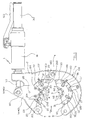
- FIGS 1-9 illustrate a portable clinching tool 1 which serves to connect rubber tubes T, typically for fluids under pressure, by means of appropriate connection elements G, of the type of that shown in figure 10 , i.e. comprising an intermediate tube I and two generally metallic connection sleeves C, within which the ends of the rubber tubes T to be connected are inserted.
- connection elements G of the type of that shown in figure 10 , i.e. comprising an intermediate tube I and two generally metallic connection sleeves C, within which the ends of the rubber tubes T to be connected are inserted.
- the tool 1 is adapted to plastically deform each connection sleeve C to make a series of circumferential crimps P on it, which, pressed against the respective rubber tube T, fix the sleeve to the tube.
- the tool 1 comprises a fixed jaw 2 and a movable jaw 3, which are mutually connected by means of a kinematic system which permits them to be mutually moved between an open rest position and a closed work position.
- Each of said jaws, 2 and 3 comprise a lunette-shaped outer body, 20 and 30, whose concavity houses an activated inner band 21 and 31, substantially shaped as a circular half-crown, which bears a set of angularly equidistant radial punches 6 arranged around their curvature axis, A and B.
- the outer bodies 20 and 30 have two respective ends which are mutually connected by means of a hinged joint 4 which permits the jaws 2 and 3 to rotate with respect to each other, along a rotation axis orthogonal to the common position plane.
- said outer bodies 20 and 30 are provided with locking means adapted to constrain the jaws 2 and 3 in the closed work position; said locking means comprise two respective through openings 5 and 5' adapted to be coaxially arranged so to receive a bolt 100 in engagement.
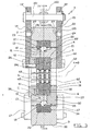
- every single activated inner band 21 and 31 comprises two respective concentric half-rings, including an inner support half-ring 22 and 32 and an outer driving half-ring 23 and 33.
- each driving half-ring 23 and 33 is partially received inside an entirely curved groove 24 and 34 made in the concave surface of the corresponding outer body 20 and 30, and is firmly fixed to the latter by means of a respective transverse elastic/cylindrical pin 102 (see fig. 7 ).
- each driving half-ring 23 and 33 projects from said curved groove 24 and 34 with a projecting section which is in turn received in an entirely curved slot 25 and 35 made in the outer surface of the corresponding support half-ring 22 and 32, so to realise a prismatic coupling which permits the support half-rings 22 and 32 to oscillate around their curvature axis, A and B (see fig. 3 ).
- each of the aforesaid curved slots 25 and 35 is provided on the bottom with a series of transverse rollers 103 integral with it, which are adapted to roll in contact with the inner surface of the corresponding driving half-rings 23 and 33 (see fig. 6 ).
- transverse rollers 103 may nevertheless not be necessary if the surfaces in contact with the driving half-rings 23, 33 and support half-rings 22, 32 are subjected to appropriate surface working and/or treatments directed towards improving the mutual sliding.
- Each support half-ring 22 and 32 is adapted to act as a seat for the radial punches 6, and comprises a series of identical, angularly equidistant prismatic engagement recesses 9 which extend radially and are adapted to slidably house a respective radial punch 6.
- a closure plate in the form of a circular half-crown 26 and 36 is fixed to each support half-ring 22 and 32, which is adapted to close said engagement recesses 9 to hold the radial punches 6 inside them, and which can be removed to permit a quick and easy substitution of the punches 6 (see figs. 1 , 2 , and 3 ).
- closure plate 36 this is composed of a single body which is fixed to the corresponding support half-ring 32 by means of two locking brackets 101. Said locking brackets 101 are fixed on the side of the support half-ring 32 and extend inward, so to surmount the closure plate 36 with a curved section 101' which is engaged in a corresponding impression, made in the closure plate 36 itself (see fig. 7 ).
- closure plate 26 is composed of a composite body, which is formed by three distinct portions, respectively 260, 261 and 262, shaped as circular sections and mutually fit with each other.
- the lateral portions 260 and 262 are fixed to the corresponding support half-ring 32 by means of a respective locking bracket 101, entirely analogous to that previously described (see figs. 1 and 2 ); while the intermediate portion 261 is screwed by the inner part of an advancing bracket 14, which will be described in greater detail below (see fig. 3 ).
- every single engagement recess 9 of each support half-ring 22 and 32 opens to the outer surface of the same by means of a housing hole 10 for a thrust section 11.
- the inner surface of each driving half-ring 23 and 33 bears, at each single thrust section 11, a shaped profile 12, against which a rolling element 13 abuts - in the example this element 13 is a sphere - and facing said thrust section 11; said rolling element 13 being received in a rolling race made in the inner surface of the corresponding driving half-ring, 23 and 33 (see fig. 3 ).
- every rolling element 13 is constantly maintained in contact with the shaped profile 12 by means of a check system comprising a first permanent magnet 60 fixed on a side of the corresponding punch 6, and a second permanent magnet 61, opposite said first magnet 60 and fixed to the closure plate 26 and 36, which faces it (see fig. 3 ).
- Said advancing brackets 14 and 15 are driven by a jack 16, firmly fixed to the outer body 20 of the fixed jaw 2, which comprises a sliding stem 160 adapted to be moved with alternating motion along a rectilinear direction orthogonal to the curvature axis A of the support half-ring 22.
- the free end of said sliding stem 160 bears a transverse pin 161, which is inserted in two mutually facing openings 14' and 15' which are respectively made in the advancing brackets 14 and 15.
- the aforesaid actuation can only occur with the jaws 2 and 3 in the closed work position, i.e. when the support half-rings 22 and 32 are in mutual contact, so that the movement imposed on the support half-ring 22 is also transmitted to the support half-ring 32.
- the support half-rings 22 and 32 are mutually spaced and can freely rotate around their own curvature axes A and B, independent from each other.
- the invention foresees constraining means.
- the support half-ring 22 is constrained by the outer body 20 of the fixed jaw 2 by means of two elastic stops 105, each borne by a respective advancing bracket 14 and 15; said elastic stops 105 being each composed of a sphere 106 which is pushed by a spring (not shown) on the respective side of the outer body 20, and which is adapted to be engaged in an impression 27 made on the outer body 20 (see fig. 3 ).
- the support half-ring 32 is constrained by the outer body 30 of the jaw 3 by means of two elastic stops 105 of the same type of those described above, which are borne by two drive brackets 17 fixed on opposite sides of the outer body 30, and whose spheres 106 are adapted to be engaged in corresponding impressions 37 made on the sides of the support half-ring 32 (see also fig. 1 ).
- the portable tool 1 is finally completed by a handgrip 162, associated with the jack 16, which is adapted to permit its handling by an operator, and by a driving lever 163 of the jack 16 itself, placed at said handgrip 162.
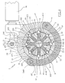
- said radial punches 6 are simultaneously pressed against the outer surface of said connection sleeve C, so to make on the sleeve C the desired circumferential crimps P.
- each radial punch 6 bears at least one tooth 62 which projects from its face turned towards the centre of the reception seat 7 and which is adapted to impress on the connection sleeve C a corresponding impression M (see fig. 10 ).
- the impressions M made by all radial punches 6 during a pressing operation result aligned along a perimeter circumference of the connection sleeve C and thus define a circumferential crimp P.
- each radial punch 6 bears three distinct, mutually spaced teeth 62 which are aligned in the axial direction, which permit making with a single pressing operation the same number of impressions M, and therefore the same number of circumferential crimps P.
- connection sleeve C due to the fact that the punches 6 are engaged in a radial direction movement, each of these is pressed on the connection sleeve C with substantially the same force.
- impressions M which they make are all substantially equal, and permit making an optimal circumferential crimp P.
- Figures 11 and 12 show an alternative and preferred embodiment of the clinching tool 1 described above.
- a first difference consists of the fact that the support half-rings 22, 32 are not free from each other, but are mutually connected by means of a hinged device 140, which is adapted to connect their ends placed in proximity to the joint 4 of the jaws 2 and 3.
- said hinged device 140 allows the support half-rings 22, 32 to rotate, separating from each other when the jaws 2, 3 are brought into open configuration, while it constrains them to stay perfectly in contact during the clinching step, when the jaws 2, 3 are in closed work position and they are engaged to rotate.
- said hinged device 140 comprises at least one generally flat connector 141, whose opposite ends are each joined to the end of a respective support half-ring 22, 32; this occurs by means of a related pivot 142 which defines a rotation axis orthogonal to the position plane of the jaws 2 and 3.
- both pivots 142 cross through the entire thickness of the support half-rings 22, 32, so to be engaged with a further connector 141 (not shown) situated on the opposite side of the support half-rings 22, 32 themselves.
- the two connectors 141 and the two through pivots 142 define overall a hinged device 140 which is substantially shaped as a chain link.
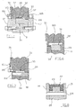
- a further difference consists in the fact that only one thrust section 110 is interposed between each punch 6 and the related shaped profile 12.
- Said thrust section 110 has a generally cylindrical shape, with a first flat end adapted to be in contact with the related punch 6, and a second end shaped as a half-sphere adapted to be in contact with the related shaped profile 12.
- the thrust section 110 moreover comprises an annular section 111 of greater diameter, which is slidably and perfectly received in a corresponding enlarged section 112 of the respective housing hole 10; said enlarged section 112 being made in the terminal part of said housing hole 10 facing the related cam profile 12.
- the number of structural components of the clinching tool 1 is advantageously reduced with respect to the first embodiment; moreover, the thrust sections 110 are always constrained by the related support half-rings 22, 32, even when the punches 6 are extracted and disassembled from the tool 1.
- closure plates 26 and 36 which are adapted to laterally close the engagement recesses 9 of the support half-rings 22 and 32 to hold the punches 6 at their interior.
- said closure plates 26, 36 are not fixed by means of the described locking brackets 101, but through related fixing screws 107 which are engaged in corresponding threaded holes made in the support half-rings 22, 32.
- Such extraction is carried out with the aid of a small tool (not shown) which is equipped with a magnet adapted to be fixed on the projecting end of a punch 6, and a handgrip for the manual movement of said magnet.
- the punch 6 is radially extracted and brought inside the annular seat 7 of the tool 1, from which it is removed by moving it parallel to the direction of the curvature axes A and B.
- a further difference consists of the fact that it foresees means adapted to indicate the rotation angle achieved by the support half-rings 22 and 32 with respect to the related outer bodies 20 and 30 during the clinching step of a connection sleeve C.
- said indicating means comprise a graduated angular scale 150 fixed to the support half-ring 32, and an indicator 151 fixed to the outer body 30.
- said graduated scale 150 is composed of a series of marks made directly on the support half-ring 32, and said indicator 151 is composed of a single mark made on the outer body 30 and adapted to be always facing the graduated scale 150.
- Figures 13-16 show an actuation device 70 not forming part of the present invention, which is applied to a portable clinching tool 1 in accordance with the first above described embodiment.
- actuation device 70 is not only associable with said tool 1, but can effectively be applied to any other type of work tool with fluid dynamic actuation.
- the actuation device 70 comprises a hydraulic jack 71 composed of an outer body 72, firmly fixed to the outer body of the tool 1, and a movable plunger 73 adapted to engage in rotation the advancing brackets 14, 15.
- the free end of the plunger 73 bears the transverse pivot 161, which is received in the facing openings 14', 15' which are made in said advancing brackets 14, 15, so to make the rotary movements of the latter compatible with the linear movement of the plunger 73.
- the plunger 73 is slidably received within a cylindrical cavity of the outer body 72, to which it is coupled by means of a plate 74.
- said cylindrical cavity is closed on the outer side by a ring nut 75 with a central hole to allow the plunger 73 to project outward; the ring nut 75 is provided with a threaded shank 76 adapted to stably connect the outer body 72 of the hydraulic jack 71 with the outer body 20 of the tool 1.
- the plate 74 defines at the inside of the cylindrical cavity a compression chamber 77, within which oil under pressure is pushed to cause the movement of the plunger 73, opposing the action of a spring 78 compressed between the plate 74 and the ring nut 75.
- the outer body 72 is provided with a reception seat 79 adapted to be coupled, by means of the interposition of seal means, with a tubular cylindrical body 80 whose outer lateral surface makes a handgrip available for the clinching tool 1 (see fig. 13 ).
- Said cylindrical body 80 is closed on the outer side by a bottom cap 81, and receives a slidable slider 82 which subdivides its inner volume into two distinct chambers, including a tank chamber 83 for the containment of the oil intended for the actuation of the hydraulic jack 71, and a vent chamber 84 placed in communication with the outside by a central hole 85 in the bottom cap 81.
- a volumetric pump indicated in its entirety with 86, is firmly associated with the hydraulic jack 71; the pump 86 is adapted to suck the oil contained in the tank chamber 83 and drive it under pressure in the compression chamber 77, so to move the plunger 73 in the direction wherein it engages the punches 6 to press against the connection sleeve C.
- Said volumetric pump 86 comprises a piston-cylinder group which is realised by a tight cylindrical cavity made in the outer body 72 of the jack 71, within which a plunger 87 is slidable received which defines, inside said cavity, a work chamber 88 communicating with the tank chamber 83 by means of a suction duct 89, and with the compression chamber 77 by means of a delivery duct 90.
- Both suction ducts 89 and delivery ducts 90 are equipped with a respective automatic valve 91 and 92, which is composed of a spherical shutter 93 movable between a closed position and an open position of the related duct, and a spring 94 adapted to push said spherical shutter 93 towards the closed position.
- the actuation device 70 comprises a kinematic group, indicated in its entirety with 120, adapted to engage the plunger 87 to move with alternating motion to drive the volumetric pump 86.
- Said kinematic group 120 is firmly associated with the hydraulic jack 71, contained inside a support box 121 fixed to the outer body 72 by means of a clamp device, and is mechanically connectable to a separate motorisation device 170 adapted to place it in operation (see fig. 13 ).
- the kinematic group 120 comprises a transmission shaft 122 rotatably coupled to the support box 121 by means of a pair of bearings 123, so to be adapted to rotate around its own central axis S, and a cam 124 keyed to said transmission shaft.
- the plunger 87 of the volumetric pump 86 projects from the outer body 72 of the jack 71 and is inserted inside a hole made in the support box 121, so that its end is in contact with the cam 124, which by rotating engages the plunger 87 to move with alternating motion.
- the invention foresees constraining means adapted to keep the plunger 87 constantly in contact with the profile of the cam 124, such means being composed in the example of a return spring 125 placed inside the work chamber 88, and adapted to push the plunger 87 against the cam 124.
- the cam 124 is preferably made from discoid body keyed on an eccentric intermediate section of the transmission shaft 122, and in the illustrated embodiment, is composed of a radial bearing, so to effectively reduce the contact friction with the plunger 87.
- the transmission shaft 122 has an overhanging section 126, projecting from the support box 121, which is adapted to act as a connection shank for the mentioned separate motorisation device 170.
- Said motorisation device 170 can be any one tool equipped with a rotating mandrel adapted to be coupled, in a removable manner, to said connection shank 126; preferable a normal drill.
- the cam 124 engages the plunger 87 to slide back and forth, sucking a certain amount of oil from the tank chamber 83 and pushing it inside the compression chamber 77, where the gradual increase of the pressure moves the plunger 73 of the hydraulic jack 71 in the direction wherein it engages the punches 6 to press against the connection sleeve C.
- the pressure inside the compression chamber 77 is connected to the tank chamber 83 also by a discharge circuit 130 (see fig. 15 ), which comprises a return duct 131 made in the outer body 72 of the hydraulic jack 71, and a maximum pressure valve 132 which intercepts said return duct 131.
- the maximum pressure valve 132 comprises a spherical shutter 133 movable between an open position and a closed position of the return duct 131, which is pushed in the closed position by a thrust stem 134.
- Said thrust stem 134 is slidably received inside a valve body 135 screwed into the outer body 72 of the jack 71, and is in turn pressed against the spherical shutter 133 by a spring 136 compressed by a threaded calibration screw 137.
- connection sleeve C When the deformation step of the connection sleeve C is completed and the volumetric pump 86 is stopped, the pressure in the compression chamber 77 prevents the plunger 73 from spontaneously withdrawing to free the connection boss from the vice of the punches 6.
- the transmission shaft 122 of the kinematic group 120 can be oriented with respect to the hydraulic jack 71 in any manner deemed appropriate.
- it is parallel to the longitudinal extension of the jack 71, while in the alternative embodiment of figure 16 it is transverse to it.
Landscapes
- Engineering & Computer Science (AREA)
- Mechanical Engineering (AREA)
- General Engineering & Computer Science (AREA)
- Automatic Assembly (AREA)
- Punching Or Piercing (AREA)
- Branch Pipes, Bends, And The Like (AREA)
- Non-Disconnectible Joints And Screw-Threaded Joints (AREA)
Claims (27)
- Werkzeug zur Verbindung von Rohren (T) mit Hilfe von Verbindungsmuffen (C), umfassend zwei Klemmbacken (2, 3), die sich zwischen einer offenen Ruheposition und einer geschlossenen Arbeitsposition beidseitig bewegen lassen, wobei sie einen ringförmigen Aufnahmesitz (7) der Verbindungsmuffe (C) definieren, und wobei sie eine umlaufende Reihe von strahlenförmig angeordneten Stempeln (6) zur Muffe (C) schwenken, wobei die Klemmbacken (2, 3) jeweils mindestens einen Stempel (6) umfassen, der mit Hilfe einer Antriebsgruppe zur Mitte des Aufnahmesitzes (7) gleitet, und wobei die Klemmbacken durch ein kinematisches System aneinander befestigt sind, mit dessen Hilfe sie bei Vorliegen in der offenen Ruheposition dem Aufnahmesitz (7) eine im Allgemeinen offene Ringform verleihen können, durch dessen seitliche Öffnung (8) die Verbindungsmuffe (C) durch Seitwärtsbewegung eingelassen und herausgezogen werden kann, und wobei die Reihe der strahlenförmig angeordneten Stempel (6) aus zwei bestimmten Abfolgen von Stempeln (6) besteht, wobei jede einzelne Abfolge mit einem aktivierten inneren Bereich (21, 31) einer entsprechenden Klemmbacke (2, 3) verbunden ist, und wobei jeder einzelne Stempel (6) jeder Abfolge so an den aktivierten inneren Bereich (21, 31) gekoppelt ist, dass er aufgrund einer auf der Rückseite befindlichen Antriebsgruppe (11, 13, 110, 60, 61) zum radialen Zurück- und Vorwärtsgleiten geeignet ist, wobei jeder einzelne aktivierte innere Bereich (21, 31) zwei konzentrische Halbringe (22, 23, 32, 33) umfasst, die zum gemeinsamen Pendeln an der gemeinsamen Krümmungsachse (A, B) entlang geeignet sind, einschließlich eines inneren Stütz-Halbrings (22, 32), der mit einer Anzahl von strahlenförmig angeordneten Eingriff-Vertiefungen (9) ausgestattet ist, die zum Aufnehmen eines entsprechenden Stempels (6) geeignet sind und ihn gleitend antreiben, und eines äußeren Antriebs-Halbrings (23, 33), der zum Antreiben der Antriebsgruppe (11, 13, 110, 60, 61) aufgrund einer ähnlichen Pendelbewegung entlang seiner eigenen Krümmungsachse (A, B) in Bezug auf den inneren Stütz-Halbring (22, 32) geeignet ist, dadurch gekennzeichnet, dass der äußere Antriebs-Halbring (23, 33) fest an der ihm zugehörigen Klemmbackenstruktur (2, 3) befestigt ist und dass der innere Stütz-Halbring (22, 32) in Bezug auf die Klemmbacke (2, 3) beweglich ist, so dass er längs seiner eigenen Krümmungsachse (A, B) pendelt.
- Werkzeug nach Anspruch 1, dadurch gekennzeichnet, dass das kinematische System ein Scharniergelenk (4) umfasst, das zwei Enden der Klemmbacken (2, 3) so verbindet, dass die letzteren dazu geeignet sind, dass sie zueinander rotieren.
- Werkzeug nach Anspruch 2, dadurch gekennzeichnet, dass die Klemmbacken (2, 3) an gegenüberliegenden Enden in Bezug auf das Scharniergelenk (4) Verschlusseinrichtungen (5, 5', 100) umfassen, die dazu geeignet sind, sie in der geschlossenen Arbeitsposition zu arretieren.
- Werkzeug nach Anspruch 3, dadurch gekennzeichnet, dass die Verschlusseinrichtungen zwei durchgehende Öffnungen (5, 5') umfassen, die so zur koaxialen Anordnung geeignet sind, dass sie eine Schraube (100) im Eingriff aufnehmen, wenn die Klemmbacken (2, 3) in der geschlossenen Arbeitsposition sind.
- Werkzeug nach Anspruch 1, dadurch gekennzeichnet, dass es Einrichtungen (150, 151) zum Markieren der mit den inneren Stütz-Halbringen (22, 32) einhergehenden Rotation in Bezug auf die äußeren Antriebs-Halbringe (23, 33) umfasst.
- Werkzeug nach Anspruch 1, dadurch gekennzeichnet, dass die inneren Stütz-Halbringe (22, 32) zwei entsprechende Enden besitzen, die mit einer Klappvorrichtung (140) verbunden sind.
- Werkzeug nach Anspruch 1, dadurch gekennzeichnet, dass der aktivierte Bereich (21, 31) eine Verschlussplatte (26, 36) umfasst, die abnehmbar an dem inneren Stütz-Halbring (22, 32) befestigt ist, der dazu geeignet ist, dass er auf einer Seite der Eingriffvertiefungen (9) für die Stempel (6) schließt.
- Werkzeug nach Anspruch 1, dadurch gekennzeichnet, dass die Innenoberfläche des äußeren Antriebs-Halbrings (23, 33) für jeden einzelnen Stempel (6) ein Formprofil (12) trägt, das als Nocke wirkt, und die Antriebsgruppe Nockenstößeleinrichtungen (11, 13, 110) umfasst, die zwischen dem Formprofil (12) und dem zugehörigen Stempel (6) eingeschoben sind.
- Werkzeug nach Anspruch 8, dadurch gekennzeichnet, dass die Nockenstößeleinrichtungen einen Wälzkörper (13), der in einem in der inneren Oberfläche des äußeren Antriebs-Halbrings (23, 33) gebildeten Wälz-Laufring aufgenommen wird, und einen Schubabschnitt (11), der in einem in dem inneren Stütz-Halbring (23, 32) gebildeten Gehäusesitz (10) aufgenommen wird, und der zwischen dem Wälzkörper (13) und dem Stempel (6) eingeschoben ist, umfassen.
- Werkzeug nach Anspruch 8, dadurch gekennzeichnet, dass die Nockenstößeleinrichtungen einen Schubabschnitt (110) umfassen, der in einem in dem inneren Stütz-Halbring (22, 32) gebildeten Gehäusesitz (10) aufgenommen wird, und der ein abgerundetes Ende aufweist, das dazu geeignet ist, dass es mit der inneren Oberfläche des äußeren Antriebs-Halbrings (23, 33) in Kontakt steht.
- Werkzeug nach Anspruch 8, dadurch gekennzeichnet, dass die Antriebsgruppe für jeden einzelnen Stempel (6) Hemmeinrichtungen (60, 61) umfasst, die dazu geeignet sind, den Stempel (6) sehr nahe an den entsprechenden Nockenstößeleinrichtungen (11, 13, 110) und dem Formprofil (12) zu halten.
- Werkzeug nach Anspruch 11, dadurch gekennzeichnet, dass die Hemmeinrichtungen einen ersten Dauermagnet (60), der einstückig mit dem Stempel (6) ist, und einen zweiten Dauermagnet (61), der einstückig mit dem Stütz-Halbring (22, 32) ist, die derart positioniert sind, dass sie konstant eine gegenseitige Anziehungskraft ausüben, die den Stempel (6) gegen die entsprechenden Nockenstößeleinrichtungen (11, 13, 110) und diese gegen das Formprofil (12) drückt, umfassen.
- Werkzeug nach Anspruch 1, dadurch gekennzeichnet, dass es Antriebseinrichtungen umfasst, die dazu geeignet sind, die inneren Stütz-Halbringe (22, 32) so zu greifen, dass sie an ihrer eigenen Krümmungsachse (A, B) entlang pendeln, wenn die Klemmbacken (2, 3) in der geschlossenen Arbeitsposition sind.
- Werkzeug nach Anspruch 13, dadurch gekennzeichnet, dass die Enden der inneren Stütz-Halbringe (22, 32) bei Vorliegen der Klemmbacken (2, 3) in der geschlossenen Arbeitsposition miteinander in Kontakt stehen, und die Antriebseinrichtungen dazu geeignet sind, nur den ersten (22) der inneren Stütz-Halbringe (22, 32) in Pendelbewegung zu erfassen, wobei der zweite innere Stütz-Halbring (32) durch den ersten inneren Stütz-Halbring (22) in Pendelbewegung erfasst wird.
- Werkzeug nach Anspruch 14, dadurch gekennzeichnet, dass die Antriebseinrichtungen zwei Vortriebsbacken (14, 15) umfassen, die an dem ersten inneren Stütz-Halbring (22) befestigt sind, welche durch einen Heber (16) bewegt werden, der fest an der Struktur der Klemmbacke (2) befestigt ist, zu der der gleiche innere Stütz-Halbring (22) gehört.
- Werkzeug nach Anspruch 15, dadurch gekennzeichnet, dass der Heber (16) einen in gradliniger Richtung beweglichen Gleitstamm (160) umfasst, der mit Hilfe eines Scharniers (161), das in zwei gegenüberliegenden Öffnungen festgehalten wird, die jeweils in einer entsprechenden Vortriebsbacke (14, 15) gebildet sind, an den Vortriebsbacken (14, 15) befestigt ist.
- Werkzeug nach Anspruch 1, dadurch gekennzeichnet, dass es mindestens acht strahlenförmig angeordnete Stempel (6) umfasst.
- Werkzeug nach Anspruch 13, dadurch gekennzeichnet, dass die Antriebseinrichtungen einen hydraulischen Heber (71), mit dem eine volumetrische Pumpe (86) fest verbunden ist und der dazu geeignet ist, eine Arbeitsflüssigkeit unter Druck im Inneren des hydraulischen Hebers (71) selbst vorzudrücken, und eine kinematische Gruppe (120) zur Betätigung der volumetrischen Pumpe (86), die fest mit dem hydraulischen Heber (71) verbunden ist und die sich mechanisch mit einer gesonderten Motorisierungsvorrichtung (170) verbinden lässt, umfassen.
- Werkzeug nach Anspruch 18, dadurch gekennzeichnet, dass die volumetrische Pumpe (86) mindestens eine Kolben-Zylinder-Gruppe umfasst, und die kinematische Gruppe (120) eine um eine festgelegte Rotationsachse (S) rotierende Nocke (124) umfasst, die dazu geeignet ist, den Stößel (87) der Kolben-Zylinder-Gruppe in abwechselnder Bewegung zu greifen.
- Werkzeug nach Anspruch 19, dadurch gekennzeichnet, dass die kinematische Gruppe (120) eine Begrenzungseinrichtung (125) umfasst, die dazu geeignet ist, den Stößel (87) in kinematischer Verbindung mit der Nocke (124) zu halten.
- Werkzeug nach Anspruch 20, dadurch gekennzeichnet, dass die Begrenzungseinrichtung eine Rückholfeder (125) umfasst, die dazu geeignet ist, den Stößel (87) in Kontakt mit dem Profil der Nocke (124) zu pressen.
- Werkzeug nach Anspruch 19, dadurch gekennzeichnet, dass die Nocke (124) durch einen scheibenförmigen Körper verwirklicht wird, der durch eine zugehörige Antriebswelle (122) in eine exzentrische Position gebracht wird.
- Werkzeug nach Anspruch 22, dadurch gekennzeichnet, dass der scheibenförmige Körper ein radiales Lager ist.
- Werkzeug nach Anspruch 19, dadurch gekennzeichnet, dass die Nocke (124) von einer Antriebswelle (122) gehalten wird, die einen Zapfen (126) zur Verbindung mit der Motorisierungsvorrichtung (170) umfasst.
- Werkzeug nach Anspruch 24, dadurch gekennzeichnet, dass die Antriebswelle (122) frei im Inneren eines Stützgehäuses (121) befestigt ist, das dazu geeignet ist, auf abnehmbare Weise am äußeren Körper (72) des hydraulischen Hebers (71) befestigt zu werden.
- Werkzeug nach Anspruch 24, dadurch gekennzeichnet, dass die Motorisierungsvorrichtung (170) ein Werkzeug ist, das einen rotierenden Dorn umfasst, der dazu geeignet ist, auf abnehmbare Weise an dem Verbindungszapfen (126) der Antriebswelle (122) befestigt zu werden.
- Werkzeug nach Anspruch 26, dadurch gekennzeichnet, dass die Motorisierungsvorrichtung (170) ein Bohrer ist.
Applications Claiming Priority (3)
| Application Number | Priority Date | Filing Date | Title |
|---|---|---|---|
| ITRE20050087 ITRE20050087A1 (it) | 2005-07-19 | 2005-07-19 | Utensile per il collegamento di tubi mediante cannotti di raccordo |
| ITRE20050106 ITRE20050106A1 (it) | 2005-09-27 | 2005-09-27 | Dispositivo per l'azionamento di utensili da lavoro |
| PCT/IB2006/001625 WO2007010339A2 (en) | 2005-07-19 | 2006-06-02 | Tool for the connection of tubes by means of connection sleeves |
Publications (2)
| Publication Number | Publication Date |
|---|---|
| EP1910035A2 EP1910035A2 (de) | 2008-04-16 |
| EP1910035B1 true EP1910035B1 (de) | 2011-10-19 |
Family
ID=37215985
Family Applications (1)
| Application Number | Title | Priority Date | Filing Date |
|---|---|---|---|
| EP06765539A Active EP1910035B1 (de) | 2005-07-19 | 2006-06-02 | Werkzeug zur verbindung von leitungen mittels verbindungsmuffen |
Country Status (4)
| Country | Link |
|---|---|
| US (1) | US8336177B2 (de) |
| EP (1) | EP1910035B1 (de) |
| AT (1) | ATE529224T1 (de) |
| WO (1) | WO2007010339A2 (de) |
Families Citing this family (23)
| Publication number | Priority date | Publication date | Assignee | Title |
|---|---|---|---|---|
| DE102006050427A1 (de) | 2006-08-22 | 2008-02-28 | Gustav Klauke Gmbh | Verfahren zum Verpressen eines Pressfittings sowie Presswerkzeug hierzu |
| DE202009009456U1 (de) * | 2009-07-15 | 2010-11-25 | Novopress Gmbh Pressen Und Presswerkzeuge & Co. Kommanditgesellschaft | Presswerkzeug zum Verbinden von insbesondere rohrförmigen Werkstücken |
| US8245789B2 (en) * | 2010-06-23 | 2012-08-21 | Halliburton Energy Service, Inc. | Apparatus and method for fluidically coupling tubular sections and tubular system formed thereby |
| DE102011052852A1 (de) | 2011-08-19 | 2013-02-21 | Gustav Klauke Gmbh | Pressvorrichtung |
| US8671536B2 (en) * | 2012-03-08 | 2014-03-18 | General Electric Company | Apparatus for installing a turbine case |
| US9463556B2 (en) | 2012-03-13 | 2016-10-11 | Hubbell Incorporated | Crimp tool force monitoring device |
| US9085023B2 (en) * | 2012-07-19 | 2015-07-21 | Dmc Power, Inc. | Swinging head swage tool |
| US9737982B2 (en) * | 2013-02-25 | 2017-08-22 | Dmc Power, Inc. | Pinned head swage tool |
| US9821363B2 (en) * | 2015-09-30 | 2017-11-21 | Ed Goff | Radial compression device with constrained dies |
| JP6774712B2 (ja) * | 2016-01-27 | 2020-10-28 | ニッタ株式会社 | 加締め用ダイおよび加締め治具、並びにそれらを用いた加締め継手の製造方法 |
| US9440280B1 (en) * | 2016-03-29 | 2016-09-13 | Peter W. Utecht | Portable hydraulic house member crimping device |
| CN106583569B (zh) * | 2017-01-23 | 2018-02-23 | 湖南金峰金属构件有限公司 | 一种多单元组合冷挤压机 |
| CN108188291A (zh) * | 2018-01-29 | 2018-06-22 | 重庆埃力森金属制品有限公司 | 管材连接用卡压装置 |
| CN109570421B (zh) * | 2018-12-15 | 2023-11-28 | 浙江雅晶电子有限公司 | 一种to管座自动打扁机 |
| CN111941346B (zh) * | 2020-07-13 | 2021-06-01 | 珠海格力电器股份有限公司 | 一种柔性螺纹件装配机构、系统、机器人及其控制方法 |
| US11090708B1 (en) * | 2020-10-02 | 2021-08-17 | Trinity Bay Equipment Holdings, LLC | Swage machine hinge systems and methods |
| US11185911B1 (en) * | 2021-03-05 | 2021-11-30 | Trinity Bay Equipment Holdings, LLC | Swage machine modular grab adapter systems and methods |
| CN113211008B (zh) * | 2021-04-10 | 2022-11-01 | 海洋石油工程(青岛)有限公司 | 一种主桩式导管架皇冠板的预制工艺 |
| CN113369859B (zh) * | 2021-06-18 | 2024-05-17 | 中国烟草总公司河南省公司 | 一种滴灌带接头的装配装置 |
| US12049765B2 (en) * | 2021-07-20 | 2024-07-30 | Life Coded, Llc | Portable hot swaged coupling device for connecting articles |
| CN113458309A (zh) * | 2021-07-29 | 2021-10-01 | 郭小当 | 一种具有自动夹持功能的生铁锻造用防形变装置 |
| CN114381830B (zh) * | 2022-01-14 | 2023-01-17 | 江南大学 | 简易式长丝喂入装置 |
| DE102022212148A1 (de) * | 2022-11-15 | 2024-05-16 | Mahle International Gmbh | Crimp-Werkzeug und damit hergestellter Wärmeübertrager |
Family Cites Families (30)
| Publication number | Priority date | Publication date | Assignee | Title |
|---|---|---|---|---|
| US1890016A (en) * | 1931-03-02 | 1932-12-06 | Frank H Smith | Cable compacting press |
| FR1173617A (fr) * | 1957-04-23 | 1959-02-27 | Souriau & Cie | Perfectionnements apportés aux moyens pour fixer un fil ou câble à l'intérieur d'un support creux ou douille |
| US3049951A (en) * | 1960-10-25 | 1962-08-21 | Amphenol Borg Electronics Corp | Portable crimping tool |
| NL269711A (de) * | 1961-06-08 | |||
| US3662450A (en) * | 1970-04-24 | 1972-05-16 | Dresser Ind | Hand-portable press for swagable pipe coupling |
| US3805580A (en) * | 1972-08-07 | 1974-04-23 | Imp Eastman Corp | Apparatus for crimping turned fittings |
| CA1037238A (en) * | 1976-08-06 | 1978-08-29 | Jackson A. Smith | Fluid-actuated, cable-type sleeve crimper |
| GB2081144B (en) * | 1980-08-01 | 1983-10-12 | Sigma Koncern | An arrangement for the radial forming of bodies |
| DE3331721C2 (de) * | 1983-09-02 | 1986-06-05 | Peter 6000 Frankfurt Schröck | Radialpresse für Werkstücke mit zylindrischer Außenfläche |
| US6044686A (en) * | 1990-04-12 | 2000-04-04 | Dischler; Helmut | Compression tool for compression molding die |
| US4989443A (en) * | 1990-04-13 | 1991-02-05 | Btm Corporation | Crimping apparatus |
| DE4240427C1 (de) * | 1992-12-02 | 1994-01-20 | Novopress Gmbh | Preßwerkzeug |
| US5353623A (en) * | 1994-04-15 | 1994-10-11 | Bobenhausen Larry F | Portable elastomeric hose crimping tool |
| DE19516830A1 (de) * | 1995-05-08 | 1996-11-14 | Veritas Gummiwerke Ag | Preßwerkzeuge und Verfahren zum Verbinden von rohrförmigen Elementen |
| US5722702A (en) * | 1996-04-12 | 1998-03-03 | Arnco Corporation | Plastic pipe compression coupler |
| US5715723A (en) * | 1996-08-14 | 1998-02-10 | Owens; Carl H. | Hose crimping apparatus |
| DE19649932A1 (de) * | 1996-12-02 | 1998-06-04 | Klauke Gmbh Gustav | Hydraulisches Handgerät |
| EP0904168A1 (de) * | 1997-03-11 | 1999-03-31 | Gustav Klauke GmbH | Presswerkzeug |
| IT1295321B1 (it) * | 1997-10-13 | 1999-05-04 | Cbc Spa | Dispositivo strozzatubi a trasmissione idraulica |
| JPH11325362A (ja) * | 1998-05-13 | 1999-11-26 | Smc Corp | 管継手 |
| EP1092487A3 (de) * | 1999-10-15 | 2004-08-25 | Gustav Klauke GmbH | Verpressgerät mit Pressbacken |
| US6324884B1 (en) * | 2000-06-30 | 2001-12-04 | Mastercool, Inc. | Hand-held portable crimping tool |
| AUPQ886200A0 (en) * | 2000-07-19 | 2000-08-10 | Betaswage Pty Ltd | Hydraulic swage press |
| DE10107579B4 (de) * | 2000-10-19 | 2012-04-26 | Gustav Klauke Gmbh | Presswerkzeug zum Verpressen von Rohrenden sowie Presseinsatz für eine Pressbacke eines Presswerkzeuges |
| US6484552B1 (en) * | 2000-12-16 | 2002-11-26 | Eaton Aeroquip, Inc. | Hinged die cage assembly |
| EP1455969B1 (de) * | 2001-12-08 | 2006-02-15 | Gustav Klauke GmbH | Pressvorrichtung |
| JP3977155B2 (ja) * | 2002-06-14 | 2007-09-19 | 株式会社オグラ | 油圧作動装置 |
| US6783394B1 (en) * | 2003-03-18 | 2004-08-31 | Randall A. Holliday | Universal multi-stage compression connector |
| JP4245989B2 (ja) * | 2003-06-20 | 2009-04-02 | 日本発條株式会社 | リング圧縮装置およびリング圧縮方法 |
| FR2870315B1 (fr) * | 2004-05-14 | 2006-06-23 | Itt Mfg Enterprises Inc | Agencement pour le racordement d'un tube rigide avec un tube souple |
-
2006
- 2006-06-02 EP EP06765539A patent/EP1910035B1/de active Active
- 2006-06-02 AT AT06765539T patent/ATE529224T1/de not_active IP Right Cessation
- 2006-06-02 US US11/995,922 patent/US8336177B2/en not_active Expired - Fee Related
- 2006-06-02 WO PCT/IB2006/001625 patent/WO2007010339A2/en not_active Ceased
Also Published As
| Publication number | Publication date |
|---|---|
| WO2007010339A2 (en) | 2007-01-25 |
| ATE529224T1 (de) | 2011-11-15 |
| WO2007010339A3 (en) | 2007-04-26 |
| US20100107393A1 (en) | 2010-05-06 |
| US8336177B2 (en) | 2012-12-25 |
| EP1910035A2 (de) | 2008-04-16 |
Similar Documents
| Publication | Publication Date | Title |
|---|---|---|
| EP1910035B1 (de) | Werkzeug zur verbindung von leitungen mittels verbindungsmuffen | |
| US9573263B2 (en) | Work tools having interchangeable work heads | |
| US5715723A (en) | Hose crimping apparatus | |
| CN105264723B (zh) | 具有可互换工作头的作业工具 | |
| CN101607390B (zh) | 电动压接工具设备 | |
| TWI579115B (zh) | 用於彎管鉗之可替換式匣 | |
| EP1750907B1 (de) | Tragbares hydraulisches Montagewerkzeug | |
| WO2015061425A1 (en) | Hydraulic power tool | |
| US20090000295A1 (en) | Press-driven tool actuation system | |
| US7155790B2 (en) | Axial swage tool | |
| US12085065B2 (en) | Pump comprising balls for displacement of fluid | |
| CN113967689B (zh) | 冲孔工具系统 | |
| CN111497262A (zh) | 使模具轴向对齐的系统和方法 | |
| US8087280B2 (en) | Spreading pliers | |
| JP2019537518A (ja) | 軸のカシメ工具 | |
| CN116917083A (zh) | 按压工具 | |
| WO2015033128A1 (en) | A hand held pipe coupling apparatus | |
| CN213436669U (zh) | 一种环压模具及管道压接工具 | |
| CN220373131U (zh) | 一种油缸装配工装 | |
| CN213381374U (zh) | 一种前端储油结构及电动液压工具 | |
| CN210178671U (zh) | 一种旋转活塞杆油缸 | |
| JP2555830Y2 (ja) | 工具交換式油圧加工装置,押圧型工具ユニット,および駆動方向変換装置 | |
| WO2023034350A1 (en) | Installation tool | |
| JPH09103911A (ja) | 手持ち式油圧加工機 | |
| KR20030020588A (ko) | 파이프 비드 성형장치 |
Legal Events
| Date | Code | Title | Description |
|---|---|---|---|
| PUAI | Public reference made under article 153(3) epc to a published international application that has entered the european phase |
Free format text: ORIGINAL CODE: 0009012 |
|
| 17P | Request for examination filed |
Effective date: 20071009 |
|
| AK | Designated contracting states |
Kind code of ref document: A2 Designated state(s): AT BE BG CH CY CZ DE DK EE ES FI FR GB GR HU IE IS IT LI LT LU LV MC NL PL PT RO SE SI SK TR |
|
| RAP1 | Party data changed (applicant data changed or rights of an application transferred) |
Owner name: AUTOCONDIZIONATORI ZANI S.R.L. |
|
| 17Q | First examination report despatched |
Effective date: 20101125 |
|
| GRAP | Despatch of communication of intention to grant a patent |
Free format text: ORIGINAL CODE: EPIDOSNIGR1 |
|
| DAX | Request for extension of the european patent (deleted) | ||
| GRAS | Grant fee paid |
Free format text: ORIGINAL CODE: EPIDOSNIGR3 |
|
| GRAA | (expected) grant |
Free format text: ORIGINAL CODE: 0009210 |
|
| AK | Designated contracting states |
Kind code of ref document: B1 Designated state(s): AT BE BG CH CY CZ DE DK EE ES FI FR GB GR HU IE IS IT LI LT LU LV MC NL PL PT RO SE SI SK TR |
|
| REG | Reference to a national code |
Ref country code: GB Ref legal event code: FG4D |
|
| REG | Reference to a national code |
Ref country code: CH Ref legal event code: EP |
|
| REG | Reference to a national code |
Ref country code: IE Ref legal event code: FG4D |
|
| REG | Reference to a national code |
Ref country code: DE Ref legal event code: R096 Ref document number: 602006025243 Country of ref document: DE Effective date: 20120126 |
|
| REG | Reference to a national code |
Ref country code: NL Ref legal event code: VDEP Effective date: 20111019 |
|
| LTIE | Lt: invalidation of european patent or patent extension |
Effective date: 20111019 |
|
| REG | Reference to a national code |
Ref country code: AT Ref legal event code: MK05 Ref document number: 529224 Country of ref document: AT Kind code of ref document: T Effective date: 20111019 |
|
| PG25 | Lapsed in a contracting state [announced via postgrant information from national office to epo] |
Ref country code: LT Free format text: LAPSE BECAUSE OF FAILURE TO SUBMIT A TRANSLATION OF THE DESCRIPTION OR TO PAY THE FEE WITHIN THE PRESCRIBED TIME-LIMIT Effective date: 20111019 Ref country code: BE Free format text: LAPSE BECAUSE OF FAILURE TO SUBMIT A TRANSLATION OF THE DESCRIPTION OR TO PAY THE FEE WITHIN THE PRESCRIBED TIME-LIMIT Effective date: 20111019 Ref country code: IS Free format text: LAPSE BECAUSE OF FAILURE TO SUBMIT A TRANSLATION OF THE DESCRIPTION OR TO PAY THE FEE WITHIN THE PRESCRIBED TIME-LIMIT Effective date: 20120219 |
|
| PG25 | Lapsed in a contracting state [announced via postgrant information from national office to epo] |
Ref country code: SE Free format text: LAPSE BECAUSE OF FAILURE TO SUBMIT A TRANSLATION OF THE DESCRIPTION OR TO PAY THE FEE WITHIN THE PRESCRIBED TIME-LIMIT Effective date: 20111019 Ref country code: PT Free format text: LAPSE BECAUSE OF FAILURE TO SUBMIT A TRANSLATION OF THE DESCRIPTION OR TO PAY THE FEE WITHIN THE PRESCRIBED TIME-LIMIT Effective date: 20120220 Ref country code: SI Free format text: LAPSE BECAUSE OF FAILURE TO SUBMIT A TRANSLATION OF THE DESCRIPTION OR TO PAY THE FEE WITHIN THE PRESCRIBED TIME-LIMIT Effective date: 20111019 Ref country code: GR Free format text: LAPSE BECAUSE OF FAILURE TO SUBMIT A TRANSLATION OF THE DESCRIPTION OR TO PAY THE FEE WITHIN THE PRESCRIBED TIME-LIMIT Effective date: 20120120 Ref country code: LV Free format text: LAPSE BECAUSE OF FAILURE TO SUBMIT A TRANSLATION OF THE DESCRIPTION OR TO PAY THE FEE WITHIN THE PRESCRIBED TIME-LIMIT Effective date: 20111019 Ref country code: NL Free format text: LAPSE BECAUSE OF FAILURE TO SUBMIT A TRANSLATION OF THE DESCRIPTION OR TO PAY THE FEE WITHIN THE PRESCRIBED TIME-LIMIT Effective date: 20111019 |
|
| PG25 | Lapsed in a contracting state [announced via postgrant information from national office to epo] |
Ref country code: CY Free format text: LAPSE BECAUSE OF FAILURE TO SUBMIT A TRANSLATION OF THE DESCRIPTION OR TO PAY THE FEE WITHIN THE PRESCRIBED TIME-LIMIT Effective date: 20111019 |
|
| PG25 | Lapsed in a contracting state [announced via postgrant information from national office to epo] |
Ref country code: BG Free format text: LAPSE BECAUSE OF FAILURE TO SUBMIT A TRANSLATION OF THE DESCRIPTION OR TO PAY THE FEE WITHIN THE PRESCRIBED TIME-LIMIT Effective date: 20120119 Ref country code: DK Free format text: LAPSE BECAUSE OF FAILURE TO SUBMIT A TRANSLATION OF THE DESCRIPTION OR TO PAY THE FEE WITHIN THE PRESCRIBED TIME-LIMIT Effective date: 20111019 Ref country code: CZ Free format text: LAPSE BECAUSE OF FAILURE TO SUBMIT A TRANSLATION OF THE DESCRIPTION OR TO PAY THE FEE WITHIN THE PRESCRIBED TIME-LIMIT Effective date: 20111019 Ref country code: SK Free format text: LAPSE BECAUSE OF FAILURE TO SUBMIT A TRANSLATION OF THE DESCRIPTION OR TO PAY THE FEE WITHIN THE PRESCRIBED TIME-LIMIT Effective date: 20111019 Ref country code: EE Free format text: LAPSE BECAUSE OF FAILURE TO SUBMIT A TRANSLATION OF THE DESCRIPTION OR TO PAY THE FEE WITHIN THE PRESCRIBED TIME-LIMIT Effective date: 20111019 |
|
| PLBE | No opposition filed within time limit |
Free format text: ORIGINAL CODE: 0009261 |
|
| STAA | Information on the status of an ep patent application or granted ep patent |
Free format text: STATUS: NO OPPOSITION FILED WITHIN TIME LIMIT |
|
| PG25 | Lapsed in a contracting state [announced via postgrant information from national office to epo] |
Ref country code: PL Free format text: LAPSE BECAUSE OF FAILURE TO SUBMIT A TRANSLATION OF THE DESCRIPTION OR TO PAY THE FEE WITHIN THE PRESCRIBED TIME-LIMIT Effective date: 20111019 Ref country code: RO Free format text: LAPSE BECAUSE OF FAILURE TO SUBMIT A TRANSLATION OF THE DESCRIPTION OR TO PAY THE FEE WITHIN THE PRESCRIBED TIME-LIMIT Effective date: 20111019 |
|
| 26N | No opposition filed |
Effective date: 20120720 |
|
| REG | Reference to a national code |
Ref country code: DE Ref legal event code: R097 Ref document number: 602006025243 Country of ref document: DE Effective date: 20120720 |
|
| PG25 | Lapsed in a contracting state [announced via postgrant information from national office to epo] |
Ref country code: AT Free format text: LAPSE BECAUSE OF FAILURE TO SUBMIT A TRANSLATION OF THE DESCRIPTION OR TO PAY THE FEE WITHIN THE PRESCRIBED TIME-LIMIT Effective date: 20111019 Ref country code: MC Free format text: LAPSE BECAUSE OF NON-PAYMENT OF DUE FEES Effective date: 20120630 |
|
| REG | Reference to a national code |
Ref country code: CH Ref legal event code: PL |
|
| REG | Reference to a national code |
Ref country code: CH Ref legal event code: PL |
|
| REG | Reference to a national code |
Ref country code: IE Ref legal event code: MM4A |
|
| PG25 | Lapsed in a contracting state [announced via postgrant information from national office to epo] |
Ref country code: LI Free format text: LAPSE BECAUSE OF NON-PAYMENT OF DUE FEES Effective date: 20120630 Ref country code: IE Free format text: LAPSE BECAUSE OF NON-PAYMENT OF DUE FEES Effective date: 20120602 Ref country code: CH Free format text: LAPSE BECAUSE OF NON-PAYMENT OF DUE FEES Effective date: 20120630 Ref country code: ES Free format text: LAPSE BECAUSE OF FAILURE TO SUBMIT A TRANSLATION OF THE DESCRIPTION OR TO PAY THE FEE WITHIN THE PRESCRIBED TIME-LIMIT Effective date: 20120130 |
|
| PG25 | Lapsed in a contracting state [announced via postgrant information from national office to epo] |
Ref country code: FI Free format text: LAPSE BECAUSE OF FAILURE TO SUBMIT A TRANSLATION OF THE DESCRIPTION OR TO PAY THE FEE WITHIN THE PRESCRIBED TIME-LIMIT Effective date: 20111019 |
|
| PG25 | Lapsed in a contracting state [announced via postgrant information from national office to epo] |
Ref country code: TR Free format text: LAPSE BECAUSE OF FAILURE TO SUBMIT A TRANSLATION OF THE DESCRIPTION OR TO PAY THE FEE WITHIN THE PRESCRIBED TIME-LIMIT Effective date: 20111019 |
|
| PG25 | Lapsed in a contracting state [announced via postgrant information from national office to epo] |
Ref country code: LU Free format text: LAPSE BECAUSE OF NON-PAYMENT OF DUE FEES Effective date: 20120602 |
|
| PG25 | Lapsed in a contracting state [announced via postgrant information from national office to epo] |
Ref country code: HU Free format text: LAPSE BECAUSE OF FAILURE TO SUBMIT A TRANSLATION OF THE DESCRIPTION OR TO PAY THE FEE WITHIN THE PRESCRIBED TIME-LIMIT Effective date: 20060602 |
|
| REG | Reference to a national code |
Ref country code: FR Ref legal event code: PLFP Year of fee payment: 11 |
|
| REG | Reference to a national code |
Ref country code: FR Ref legal event code: PLFP Year of fee payment: 12 |
|
| PGFP | Annual fee paid to national office [announced via postgrant information from national office to epo] |
Ref country code: GB Payment date: 20170627 Year of fee payment: 12 |
|
| REG | Reference to a national code |
Ref country code: FR Ref legal event code: PLFP Year of fee payment: 13 |
|
| PGFP | Annual fee paid to national office [announced via postgrant information from national office to epo] |
Ref country code: DE Payment date: 20180627 Year of fee payment: 13 |
|
| GBPC | Gb: european patent ceased through non-payment of renewal fee |
Effective date: 20180602 |
|
| PG25 | Lapsed in a contracting state [announced via postgrant information from national office to epo] |
Ref country code: GB Free format text: LAPSE BECAUSE OF NON-PAYMENT OF DUE FEES Effective date: 20180602 |
|
| REG | Reference to a national code |
Ref country code: DE Ref legal event code: R119 Ref document number: 602006025243 Country of ref document: DE |
|
| PG25 | Lapsed in a contracting state [announced via postgrant information from national office to epo] |
Ref country code: DE Free format text: LAPSE BECAUSE OF NON-PAYMENT OF DUE FEES Effective date: 20200101 |
|
| PGFP | Annual fee paid to national office [announced via postgrant information from national office to epo] |
Ref country code: IT Payment date: 20250326 Year of fee payment: 20 |
|
| PGFP | Annual fee paid to national office [announced via postgrant information from national office to epo] |
Ref country code: FR Payment date: 20250625 Year of fee payment: 20 |