EP1910042B1 - Tete de coupe destinee a un rasoir electrique - Google Patents
Tete de coupe destinee a un rasoir electrique Download PDFInfo
- Publication number
- EP1910042B1 EP1910042B1 EP06762771A EP06762771A EP1910042B1 EP 1910042 B1 EP1910042 B1 EP 1910042B1 EP 06762771 A EP06762771 A EP 06762771A EP 06762771 A EP06762771 A EP 06762771A EP 1910042 B1 EP1910042 B1 EP 1910042B1
- Authority
- EP
- European Patent Office
- Prior art keywords
- blade
- shaving head
- head according
- cutting edge
- edge
- Prior art date
- Legal status (The legal status is an assumption and is not a legal conclusion. Google has not performed a legal analysis and makes no representation as to the accuracy of the status listed.)
- Active
Links
Images


Classifications
-
- B—PERFORMING OPERATIONS; TRANSPORTING
- B26—HAND CUTTING TOOLS; CUTTING; SEVERING
- B26B—HAND-HELD CUTTING TOOLS NOT OTHERWISE PROVIDED FOR
- B26B19/00—Clippers or shavers operating with a plurality of cutting edges, e.g. hair clippers, dry shavers
- B26B19/02—Clippers or shavers operating with a plurality of cutting edges, e.g. hair clippers, dry shavers of the reciprocating-cutter type
- B26B19/04—Cutting heads therefor; Cutters therefor; Securing equipment thereof
- B26B19/044—Manufacture and assembly of cutter blocks
-
- B—PERFORMING OPERATIONS; TRANSPORTING
- B26—HAND CUTTING TOOLS; CUTTING; SEVERING
- B26B—HAND-HELD CUTTING TOOLS NOT OTHERWISE PROVIDED FOR
- B26B19/00—Clippers or shavers operating with a plurality of cutting edges, e.g. hair clippers, dry shavers
- B26B19/02—Clippers or shavers operating with a plurality of cutting edges, e.g. hair clippers, dry shavers of the reciprocating-cutter type
- B26B19/04—Cutting heads therefor; Cutters therefor; Securing equipment thereof
Definitions
- the invention relates to a shaving head for an electric shaver, comprising a lower blade, the at least one in at least one direction of movement relative to an at least partially surrounding upper blade linearly oscillating driven blade, which is provided with at least one pointing in the direction of movement cutting edge.
- Such formed from a combination with a lower and a top blade shaving head is for example from the EP-B-0 743 144 known.
- the upper blade of this shaving head is designed as a perforated foil and cooperates with a lower blade formed from a plurality of blades, in which the cutting edges of the individual blades have a cutting angle of less than 90 °.
- From the DE-C-44 23 503 is known a bottom blade for such a shaving head, in which the blades have a cutting edge angle of 90 °.
- the object of the present invention is to obtain the advantages of the sharp-edged lower blades in relation to the low cutting forces, while still avoiding skin irritations by shaving and to obtain the superior skin care of the cutting systems with right-angled cutting edge.
- This object is achieved in that the blade having a relation to the cutting edge raised, pointing in the direction of the upper blade, outer boundary portion which increases from the cutting edge to the upper blade out.
- a razor is known, the shaving foil (upper blade) is arcuately curved, and the inner cutting body (lower blade) along these arcuate edges of the shaving foil is reciprocated.
- the shaving head according to the invention can be used in a wide variety of types of electric shavers, it being particularly advantageous if the lower blade has a plurality of blades.
- the at least one blade has two mutually opposite cutting edges.
- the edge angle of the cutting edge which is formed by the inner and outer legs of the edge angle, is less than or equal to 90 °, it has been found that optimum shaving performance can be achieved with edge angles between 20 ° and 90 °, preferably about 45 °.
- the lower cutting forces also reduce the risk of vibration dips due to high load in oscillating shear systems.
- the shaving results are very much influenced by the radius of the cutting edge, with excellent shaving results with edge radii less than or equal to 2 microns, preferably less than or equal to 1 micron, can be achieved.
- the height difference between the outermost point of the raised boundary section and the cutting edge is between 1 ⁇ m and 20 ⁇ m. It should be noted that too large gaps between the lower and the upper blade can cause a possibility for pulling the hair to be shaved between the two parts shaving, which can lead to a painful Zupf bin that is to be avoided.
- a preferred embodiment of the invention provides that the angle of attack, ie the angle between the direction of movement of the lower blade and the outer leg of the edge angle, between 20 ° and 1 °, preferably between 2 ° and 5 °.
- the angle of attack ie the angle between the direction of movement of the lower blade and the outer leg of the edge angle, between 20 ° and 1 °, preferably between 2 ° and 5 °.
- the outer boundary line ie the course between the cutting edge and the raised area, can be linear or else at least partially spherical. It is important that the contour of the outer limiting section 17 be continuous, i. without a jump, in particular without a jump, runs.
- a particularly cost-producible embodiment provides that the lower blade is formed from a molded sheet metal part, wherein preferably the lower blade or at least the cutting edge are made on etching path. It is particularly favorable with regard to the service life of the shearing part when the blade is at least partially provided with a wear protection layer.
- the in Fig. 1 shown dry shaver consists of a housing 1, which serves among other things, the inclusion of an electric motor and optionally accumulators for energy storage and is provided with an on / off switch 2. At the upper end an oscillating driven drive element 3 is led out of the housing 1.
- the lower blade 4, which consists in particular of the shear elements 5, has a coupling pin 6, which can be locked to the drive element 3. In this way, the two mutually parallel shearing elements 5 can then be driven in an oscillating manner along its longitudinal extension (double arrow 16).
- the lower blade 4 is at least partially surrounded by an upper blade 7, which is composed of a removable frame, which can be latched to the housing 1, and made of shear plates 9 attached to the removable frame 8.
- the shaving foils 9 are perforated flat with passage openings which can be embodied as holes and / or slits, and through which the hair to be shaved enters the shaving head during the shaving process. Due to the cutting edges formed on both the film passage holes and the shear elements 5 of the lower blade 4 and the movement of the lower blade 4 relative to the upper blade 7, hairs entering the shaving head are sheared between the respective cutting edges.
- Fig. 2 shows in enlarged scale a shear element 5 of the lower blade 4, in which a plurality of blades 10 - in this case, parallel to each other - is arranged.
- the blades 10 of the lower blade 4 are U-shaped, wherein at the free edges of the strip-shaped, bent into a U blades 10 and the cutting edges 11 each arcuately rotate and are remote from each other.
- the aligned along the direction of movement of the lower blade 4 strip-shaped portion 12 serves to attach the shear element 5 to a coupling piece by means of which a connection to the drive is made.
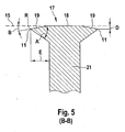
- Fig. 4 shows the interaction between lower, upper blade and the skin to be shaved 13.
- a portion of the skin 13 is pressed through an opening 14 of the shaving foil 9 in the shaving head.
- only one blade 10 is shown, on the outer contour of which the foil 9 is supported, whereby the contact plane 15 is formed in this area.
- This blade can optionally be used to increase the mechanical stability.
- the outer limiting portion 17 of the blade 10, which extends between the two opposing cutting edges 11, has a central raised portion 18 which is planar and extends along the contact plane 15. These are followed by the outer slopes 19, which, starting from the cutting edges 11 to the central raised portion 18 with the angle of attack B outside, i. rise in the drawing upwards.
- This angle of attack B is in terms of amount between 22 ° and 1 °, preferably 2 ° to 5 °.
- the edge radius R of the cutting edges 11 is 2 ⁇ m or less, preferably even less than 1 ⁇ m.
- the edge angle A of the wedge-shaped cutting edges 11 is 90 ° or less, as the preferred angular amount has been found to be 45 ° ⁇ 10 °.
- the height difference D between the raised portion 18 and the cutting edge 11 is selected in terms of amount between 1 micron and 20 microns. If he were chosen too large, there would be the risk of pulling hair between the foil and the bottom knife, which would not cut this hair, but only clamped or torn.
- edge angle A of about 45 ° is a compromise between required stability of the cutting edge and still the lowest possible cutting forces. While too large edge angle hair is not optimally separated, too low wedge angle lead to stability problems, such as edge breakouts or local Kantenumbiegonne.
- the edge projection E of the cutting edge 11, ie the extension of the cutting wedge along the direction of movement 16, should be more than 50 ⁇ m, if possible even 100 ⁇ m or more. This ensures that the wedge of the cutting edge 11 completely penetrate into the hair and it can cut through it.
- the transition from the cutting edge 11 to the central raised portion 18 of the outer boundary portion does not necessarily have to be made with straight contours in cross-section contours, but it is also a spherical design of the outer boundary portion possible, in which the transition 19 is not is formed as an oblique, but as a convex curved contour. However, it must be ensured that this convex contour extends substantially within the specified edge angle A.
Landscapes
- Engineering & Computer Science (AREA)
- Life Sciences & Earth Sciences (AREA)
- Forests & Forestry (AREA)
- Mechanical Engineering (AREA)
- Manufacturing & Machinery (AREA)
- Dry Shavers And Clippers (AREA)
- Nonmetal Cutting Devices (AREA)
Claims (12)
- Tête de coupe pour un appareil de rasage électrique, comprenant un couteau inférieur (4) qui présente au moins une lame (10) entraînée de manière oscillante et linéaire dans au moins une direction de déplacement (16) par rapport à un couteau supérieur (7) qui l'entoure au moins partiellement et munie respectivement d'au moins une arête de coupe (11) orientée dans la direction de déplacement,
caractérisée en ce que,
la lame (10) présente une section de délimitation (17) extérieure surélevée par rapport à l'arête de coupe (11) et orientée en direction du couteau supérieur (7), qui surplombe l'arête de coupe (11) vers le couteau supérieur (7). - Tête de coupe selon la revendication 1,
caractérisée en ce que,
le couteau inférieur (7) présente une pluralité de lames (10). - Tête de coupe selon l'une des revendications précédentes,
caractérisée en ce que,
la au moins une lame (10) présente deux arêtes de coupe (11) situées vis-à-vis l'une de l'autre. - Tête de coupe selon l'une des revendications précédentes,
caractérisée en ce que,
l'angle d'arête (A) de l'arête de coupe (11) est inférieur ou égal à 90°. - Tête de coupe selon la revendication 4,
caractérisée en ce que,
l'angle d'arête (A) est compris entre 20° et 90°, et est de préférence de 45°. - Tête de coupe selon l'une des revendications précédentes,
caractérisée en ce que,
le rayon d'arête (R) de l'arête de coupe (11) est inférieur ou égal à 2 µm, de préférence inférieur ou égal à 1 µm. - Tête de coupe selon l'une des revendications précédentes,
caractérisée en ce que,
la différence de hauteur (D) entre le point le plus extérieur de la section de délimitation (18) surélevée et l'arête de coupe (11) est comprise entre 1 µm et 20 µm. - Tête de coupe selon l'une des revendications précédentes,
caractérisée en ce que,
l'angle (B) entre la direction de déplacement du couteau inférieur (4) et le côté extérieur de l'angle d'arête (A) est compris entre 22° et 1 °, de préférence entre 2° et 5°. - Tête de coupe selon l'une des revendications précédentes,
caractérisée en ce que,
la ligne de délimitation (17) extérieure de la lame (10) est réalisée de manière au moins partiellement bombée. - Tête de coupe selon l'une des revendications précédentes,
caractérisée en ce que,
le couteau inférieur (4) est constitué d'une pièce en tôle profilée. - Tête de coupe selon l'une des revendications précédentes,
caractérisée en ce que,
le couteau inférieur (4) ou au moins l'arête de coupe (11) est fabriqué par voie de gravure. - Tête de coupe selon l'une des revendications précédentes,
caractérisée en ce que,
la lame (10) est munie au moins partiellement d'une couche de protection contre l'usure.
Applications Claiming Priority (2)
| Application Number | Priority Date | Filing Date | Title |
|---|---|---|---|
| DE102005036383A DE102005036383A1 (de) | 2005-07-29 | 2005-07-29 | Scherkopf für einen elektrischen Rasierapparat |
| PCT/EP2006/007231 WO2007014660A1 (fr) | 2005-07-29 | 2006-07-22 | Tete de coupe destinee a un rasoir electrique |
Publications (2)
| Publication Number | Publication Date |
|---|---|
| EP1910042A1 EP1910042A1 (fr) | 2008-04-16 |
| EP1910042B1 true EP1910042B1 (fr) | 2010-01-20 |
Family
ID=37111745
Family Applications (1)
| Application Number | Title | Priority Date | Filing Date |
|---|---|---|---|
| EP06762771A Active EP1910042B1 (fr) | 2005-07-29 | 2006-07-22 | Tete de coupe destinee a un rasoir electrique |
Country Status (8)
| Country | Link |
|---|---|
| US (1) | US8082670B2 (fr) |
| EP (1) | EP1910042B1 (fr) |
| JP (1) | JP5026419B2 (fr) |
| CN (1) | CN101232981B (fr) |
| AT (1) | ATE455627T1 (fr) |
| DE (2) | DE102005036383A1 (fr) |
| RU (1) | RU2401192C2 (fr) |
| WO (1) | WO2007014660A1 (fr) |
Families Citing this family (5)
| Publication number | Priority date | Publication date | Assignee | Title |
|---|---|---|---|---|
| DE102008027224A1 (de) * | 2008-06-06 | 2009-12-10 | Braun Gmbh | Untermesser für den Scherkopf eines Trockenrasierapparates |
| USD676602S1 (en) * | 2011-01-12 | 2013-02-19 | Braun Gmbh | Cleaning center for a shaver |
| US20140311306A1 (en) * | 2011-11-08 | 2014-10-23 | Koninklijke Philips N.V. | Hair cutting device with improved cutting member |
| WO2014091719A1 (fr) | 2012-12-13 | 2014-06-19 | パナソニック 株式会社 | Rasoir électrique |
| USD983455S1 (en) * | 2020-10-15 | 2023-04-11 | Skull Shaver, Llc | Electric shaver foil head |
Family Cites Families (28)
| Publication number | Priority date | Publication date | Assignee | Title |
|---|---|---|---|---|
| US2206551A (en) * | 1936-09-21 | 1940-07-02 | Gillette Safety Razor Co | Shaving implement |
| US2824367A (en) * | 1955-06-22 | 1958-02-25 | Arthur C Mcwilliams | Dry shaver having combination suction and adjustable cutting means |
| US3002276A (en) * | 1957-12-04 | 1961-10-03 | Kobler Paul | Knives in mechanical shavers |
| US3064348A (en) * | 1960-02-15 | 1962-11-20 | Wahl Clipper Corp | Blade for a dry shaver |
| JPS4115385Y1 (fr) * | 1964-09-22 | 1966-07-19 | ||
| GB1469556A (en) * | 1974-07-23 | 1977-04-06 | Gillette Co | Dry shavers |
| JPS5116151A (en) | 1974-07-29 | 1976-02-09 | Hamasawa Kogyo Kk | Denkikamisorino uchiba |
| US4343089A (en) * | 1979-10-03 | 1982-08-10 | Matsushita Electric Works, Ltd. | Outer blade of electric shavers |
| SU885004A1 (ru) * | 1979-12-05 | 1981-11-30 | Харьковское Производственное Объединение "Электробытприбор" | Режуща головка электробритвы |
| JPS57156787A (en) * | 1981-03-20 | 1982-09-28 | Hitachi Maxell | Inner edge for reciprocating type electric razor |
| JPS58169859U (ja) * | 1982-05-11 | 1983-11-12 | 東芝テック株式会社 | 電気カミソリ器 |
| JP3427213B2 (ja) * | 1992-11-25 | 2003-07-14 | 松下電工株式会社 | 往復式電気かみそりの内刃 |
| US5473818A (en) * | 1992-11-25 | 1995-12-12 | Matsushita Electric Works, Ltd. | Reciprocatory dry shaver |
| RU2113981C1 (ru) * | 1993-02-02 | 1998-06-27 | Уфимское приборостроительное производственное объединение | Режущая головка электробритвы |
| JPH07148361A (ja) | 1993-11-29 | 1995-06-13 | Sanyo Electric Co Ltd | 電気かみそりの内刃とその製造方法 |
| DE4413352C1 (de) * | 1994-04-18 | 1995-05-04 | Braun Ag | Verfahren zur Herstellung eines Messers für eine Schneideinrichtung eines elektrischen Rasierapparates oder Bartschneiders |
| DE4423503C1 (de) * | 1994-07-05 | 1995-04-20 | Braun Ag | Untermesser für einen Trockenrasierapparat |
| EP0743144B1 (fr) | 1995-05-19 | 2000-10-11 | Matsushita Electric Works, Ltd. | Assemblage coupant pour rasoir électrique |
| US6769179B2 (en) * | 2000-07-06 | 2004-08-03 | Teizoh Satoh | Shaver |
| JP2002058887A (ja) * | 2000-08-22 | 2002-02-26 | Matsushita Electric Works Ltd | 電気かみそりの刃 |
| JPWO2003016000A1 (ja) * | 2001-08-10 | 2004-12-02 | 松下電工株式会社 | 電気かみそり用の内刃 |
| JP4338422B2 (ja) * | 2002-04-18 | 2009-10-07 | 株式会社泉精器製作所 | 回転式電気かみそりの内刃ユニット |
| JP4261284B2 (ja) | 2003-08-18 | 2009-04-30 | 九州日立マクセル株式会社 | 電気かみそり |
| JP2005168631A (ja) | 2003-12-09 | 2005-06-30 | Izumi Products Co | 往復式電気かみそり |
| JP2005198795A (ja) * | 2004-01-15 | 2005-07-28 | Izumi Products Co | 往復式電気かみそりの内刃製造方法および内刃 |
| US20060143924A1 (en) * | 2004-12-30 | 2006-07-06 | Rovcal, Inc. | Electric shaver |
| DE102006023774A1 (de) * | 2006-05-20 | 2007-11-22 | Braun Gmbh | Untermesser für einen Trockenrasiererscherkopf |
| DE102008027224A1 (de) * | 2008-06-06 | 2009-12-10 | Braun Gmbh | Untermesser für den Scherkopf eines Trockenrasierapparates |
-
2005
- 2005-07-29 DE DE102005036383A patent/DE102005036383A1/de not_active Withdrawn
-
2006
- 2006-07-22 US US11/996,575 patent/US8082670B2/en active Active
- 2006-07-22 DE DE502006005984T patent/DE502006005984D1/de active Active
- 2006-07-22 CN CN2006800279136A patent/CN101232981B/zh active Active
- 2006-07-22 AT AT06762771T patent/ATE455627T1/de active
- 2006-07-22 EP EP06762771A patent/EP1910042B1/fr active Active
- 2006-07-22 WO PCT/EP2006/007231 patent/WO2007014660A1/fr not_active Ceased
- 2006-07-22 RU RU2008107730/02A patent/RU2401192C2/ru not_active IP Right Cessation
- 2006-07-22 JP JP2008523202A patent/JP5026419B2/ja active Active
Also Published As
| Publication number | Publication date |
|---|---|
| CN101232981B (zh) | 2010-12-08 |
| DE502006005984D1 (de) | 2010-03-11 |
| WO2007014660A1 (fr) | 2007-02-08 |
| US8082670B2 (en) | 2011-12-27 |
| JP2009502278A (ja) | 2009-01-29 |
| RU2008107730A (ru) | 2009-09-10 |
| ATE455627T1 (de) | 2010-02-15 |
| JP5026419B2 (ja) | 2012-09-12 |
| US20090133265A1 (en) | 2009-05-28 |
| RU2401192C2 (ru) | 2010-10-10 |
| CN101232981A (zh) | 2008-07-30 |
| DE102005036383A1 (de) | 2007-02-01 |
| EP1910042A1 (fr) | 2008-04-16 |
Similar Documents
| Publication | Publication Date | Title |
|---|---|---|
| EP1667822B1 (fr) | Systeme de coupe pour un appareil electrique d'elimination de poils | |
| EP2146827B1 (fr) | Dispositif de coupe pour la coupe des poils | |
| EP2346651B1 (fr) | Tête coupante pour un rasoir | |
| EP2035194B1 (fr) | Unité de cisaillement pour rasoir électrique | |
| DE69321246T2 (de) | Einschubige reinigungsvorrichtung für eine flexibele nassrasiereinheit | |
| EP1827777B1 (fr) | Appareil pour raser et couper les cheveux | |
| EP2303524B1 (fr) | Couteau inférieur pour la tête de coupe d'un rasoir électrique | |
| EP1910042B1 (fr) | Tete de coupe destinee a un rasoir electrique | |
| DE102009035232A1 (de) | Schneidsatz für Haarschneidemaschinen | |
| DE2937432C2 (fr) | ||
| EP1370397B1 (fr) | Systeme de rasage pour un rasoir electrique | |
| DE1927032A1 (de) | Elektrischer Trockenrasierer | |
| EP2021153B1 (fr) | Couteau inférieur pour une tête de coupe d'un rasoir à sec | |
| EP1838502B1 (fr) | Tondeuse electrique pour les cheveux | |
| DE202008002467U1 (de) | Schneidsatz für elektrische Haarschneidemaschinen | |
| EP0086536B1 (fr) | Assemblage des lames coupantes à mouvement de va-et-vient pour rasoir à sec | |
| DE69800963T2 (de) | Sicherheitsrasierer | |
| EP3974127B1 (fr) | Rasoir mécanique | |
| DE2850800C2 (fr) | ||
| EP3784453B1 (fr) | Tête de coupe | |
| DE102008048725A1 (de) | Haarentfernungsgerät mit Vorrichtung zur Vorbereitung der Haut | |
| DE102009031626A1 (de) | Schereinheit für einen Trockenrasierer mit Hautprotektoren | |
| DE102009031627A1 (de) | Untermesser-Baugruppe für Trockenrasierer |
Legal Events
| Date | Code | Title | Description |
|---|---|---|---|
| PUAI | Public reference made under article 153(3) epc to a published international application that has entered the european phase |
Free format text: ORIGINAL CODE: 0009012 |
|
| 17P | Request for examination filed |
Effective date: 20071214 |
|
| AK | Designated contracting states |
Kind code of ref document: A1 Designated state(s): AT BE BG CH CY CZ DE DK EE ES FI FR GB GR HU IE IS IT LI LT LU LV MC NL PL PT RO SE SI SK TR |
|
| 17Q | First examination report despatched |
Effective date: 20080804 |
|
| GRAP | Despatch of communication of intention to grant a patent |
Free format text: ORIGINAL CODE: EPIDOSNIGR1 |
|
| DAX | Request for extension of the european patent (deleted) | ||
| GRAS | Grant fee paid |
Free format text: ORIGINAL CODE: EPIDOSNIGR3 |
|
| GRAA | (expected) grant |
Free format text: ORIGINAL CODE: 0009210 |
|
| AK | Designated contracting states |
Kind code of ref document: B1 Designated state(s): AT BE BG CH CY CZ DE DK EE ES FI FR GB GR HU IE IS IT LI LT LU LV MC NL PL PT RO SE SI SK TR |
|
| REG | Reference to a national code |
Ref country code: GB Ref legal event code: FG4D Free format text: NOT ENGLISH |
|
| REG | Reference to a national code |
Ref country code: CH Ref legal event code: EP |
|
| REG | Reference to a national code |
Ref country code: IE Ref legal event code: FG4D |
|
| REF | Corresponds to: |
Ref document number: 502006005984 Country of ref document: DE Date of ref document: 20100311 Kind code of ref document: P |
|
| REG | Reference to a national code |
Ref country code: CH Ref legal event code: NV Representative=s name: BOHEST AG |
|
| REG | Reference to a national code |
Ref country code: NL Ref legal event code: VDEP Effective date: 20100120 |
|
| LTIE | Lt: invalidation of european patent or patent extension |
Effective date: 20100120 |
|
| PG25 | Lapsed in a contracting state [announced via postgrant information from national office to epo] |
Ref country code: ES Free format text: LAPSE BECAUSE OF FAILURE TO SUBMIT A TRANSLATION OF THE DESCRIPTION OR TO PAY THE FEE WITHIN THE PRESCRIBED TIME-LIMIT Effective date: 20100501 Ref country code: IS Free format text: LAPSE BECAUSE OF FAILURE TO SUBMIT A TRANSLATION OF THE DESCRIPTION OR TO PAY THE FEE WITHIN THE PRESCRIBED TIME-LIMIT Effective date: 20100520 Ref country code: PT Free format text: LAPSE BECAUSE OF FAILURE TO SUBMIT A TRANSLATION OF THE DESCRIPTION OR TO PAY THE FEE WITHIN THE PRESCRIBED TIME-LIMIT Effective date: 20100520 Ref country code: NL Free format text: LAPSE BECAUSE OF FAILURE TO SUBMIT A TRANSLATION OF THE DESCRIPTION OR TO PAY THE FEE WITHIN THE PRESCRIBED TIME-LIMIT Effective date: 20100120 Ref country code: LT Free format text: LAPSE BECAUSE OF FAILURE TO SUBMIT A TRANSLATION OF THE DESCRIPTION OR TO PAY THE FEE WITHIN THE PRESCRIBED TIME-LIMIT Effective date: 20100120 |
|
| REG | Reference to a national code |
Ref country code: IE Ref legal event code: FD4D |
|
| PG25 | Lapsed in a contracting state [announced via postgrant information from national office to epo] |
Ref country code: SI Free format text: LAPSE BECAUSE OF FAILURE TO SUBMIT A TRANSLATION OF THE DESCRIPTION OR TO PAY THE FEE WITHIN THE PRESCRIBED TIME-LIMIT Effective date: 20100120 Ref country code: PL Free format text: LAPSE BECAUSE OF FAILURE TO SUBMIT A TRANSLATION OF THE DESCRIPTION OR TO PAY THE FEE WITHIN THE PRESCRIBED TIME-LIMIT Effective date: 20100120 Ref country code: FI Free format text: LAPSE BECAUSE OF FAILURE TO SUBMIT A TRANSLATION OF THE DESCRIPTION OR TO PAY THE FEE WITHIN THE PRESCRIBED TIME-LIMIT Effective date: 20100120 Ref country code: LV Free format text: LAPSE BECAUSE OF FAILURE TO SUBMIT A TRANSLATION OF THE DESCRIPTION OR TO PAY THE FEE WITHIN THE PRESCRIBED TIME-LIMIT Effective date: 20100120 |
|
| PG25 | Lapsed in a contracting state [announced via postgrant information from national office to epo] |
Ref country code: CY Free format text: LAPSE BECAUSE OF FAILURE TO SUBMIT A TRANSLATION OF THE DESCRIPTION OR TO PAY THE FEE WITHIN THE PRESCRIBED TIME-LIMIT Effective date: 20100120 Ref country code: EE Free format text: LAPSE BECAUSE OF FAILURE TO SUBMIT A TRANSLATION OF THE DESCRIPTION OR TO PAY THE FEE WITHIN THE PRESCRIBED TIME-LIMIT Effective date: 20100120 Ref country code: GR Free format text: LAPSE BECAUSE OF FAILURE TO SUBMIT A TRANSLATION OF THE DESCRIPTION OR TO PAY THE FEE WITHIN THE PRESCRIBED TIME-LIMIT Effective date: 20100421 Ref country code: IE Free format text: LAPSE BECAUSE OF FAILURE TO SUBMIT A TRANSLATION OF THE DESCRIPTION OR TO PAY THE FEE WITHIN THE PRESCRIBED TIME-LIMIT Effective date: 20100120 Ref country code: RO Free format text: LAPSE BECAUSE OF FAILURE TO SUBMIT A TRANSLATION OF THE DESCRIPTION OR TO PAY THE FEE WITHIN THE PRESCRIBED TIME-LIMIT Effective date: 20100120 Ref country code: SE Free format text: LAPSE BECAUSE OF FAILURE TO SUBMIT A TRANSLATION OF THE DESCRIPTION OR TO PAY THE FEE WITHIN THE PRESCRIBED TIME-LIMIT Effective date: 20100120 |
|
| PLBE | No opposition filed within time limit |
Free format text: ORIGINAL CODE: 0009261 |
|
| STAA | Information on the status of an ep patent application or granted ep patent |
Free format text: STATUS: NO OPPOSITION FILED WITHIN TIME LIMIT |
|
| PG25 | Lapsed in a contracting state [announced via postgrant information from national office to epo] |
Ref country code: CZ Free format text: LAPSE BECAUSE OF FAILURE TO SUBMIT A TRANSLATION OF THE DESCRIPTION OR TO PAY THE FEE WITHIN THE PRESCRIBED TIME-LIMIT Effective date: 20100120 Ref country code: SK Free format text: LAPSE BECAUSE OF FAILURE TO SUBMIT A TRANSLATION OF THE DESCRIPTION OR TO PAY THE FEE WITHIN THE PRESCRIBED TIME-LIMIT Effective date: 20100120 Ref country code: BG Free format text: LAPSE BECAUSE OF FAILURE TO SUBMIT A TRANSLATION OF THE DESCRIPTION OR TO PAY THE FEE WITHIN THE PRESCRIBED TIME-LIMIT Effective date: 20100420 |
|
| 26N | No opposition filed |
Effective date: 20101021 |
|
| PG25 | Lapsed in a contracting state [announced via postgrant information from national office to epo] |
Ref country code: DK Free format text: LAPSE BECAUSE OF FAILURE TO SUBMIT A TRANSLATION OF THE DESCRIPTION OR TO PAY THE FEE WITHIN THE PRESCRIBED TIME-LIMIT Effective date: 20100120 |
|
| PG25 | Lapsed in a contracting state [announced via postgrant information from national office to epo] |
Ref country code: MC Free format text: LAPSE BECAUSE OF NON-PAYMENT OF DUE FEES Effective date: 20100731 |
|
| PG25 | Lapsed in a contracting state [announced via postgrant information from national office to epo] |
Ref country code: IT Free format text: LAPSE BECAUSE OF FAILURE TO SUBMIT A TRANSLATION OF THE DESCRIPTION OR TO PAY THE FEE WITHIN THE PRESCRIBED TIME-LIMIT Effective date: 20100120 |
|
| PG25 | Lapsed in a contracting state [announced via postgrant information from national office to epo] |
Ref country code: HU Free format text: LAPSE BECAUSE OF FAILURE TO SUBMIT A TRANSLATION OF THE DESCRIPTION OR TO PAY THE FEE WITHIN THE PRESCRIBED TIME-LIMIT Effective date: 20100721 Ref country code: LU Free format text: LAPSE BECAUSE OF NON-PAYMENT OF DUE FEES Effective date: 20100722 |
|
| PG25 | Lapsed in a contracting state [announced via postgrant information from national office to epo] |
Ref country code: TR Free format text: LAPSE BECAUSE OF FAILURE TO SUBMIT A TRANSLATION OF THE DESCRIPTION OR TO PAY THE FEE WITHIN THE PRESCRIBED TIME-LIMIT Effective date: 20100120 |
|
| REG | Reference to a national code |
Ref country code: FR Ref legal event code: PLFP Year of fee payment: 11 |
|
| REG | Reference to a national code |
Ref country code: FR Ref legal event code: PLFP Year of fee payment: 12 |
|
| REG | Reference to a national code |
Ref country code: FR Ref legal event code: PLFP Year of fee payment: 13 |
|
| PGFP | Annual fee paid to national office [announced via postgrant information from national office to epo] |
Ref country code: IT Payment date: 20180531 Year of fee payment: 4 |
|
| PGFP | Annual fee paid to national office [announced via postgrant information from national office to epo] |
Ref country code: CH Payment date: 20180713 Year of fee payment: 13 |
|
| REG | Reference to a national code |
Ref country code: CH Ref legal event code: PL |
|
| REG | Reference to a national code |
Ref country code: AT Ref legal event code: MM01 Ref document number: 455627 Country of ref document: AT Kind code of ref document: T Effective date: 20190722 |
|
| REG | Reference to a national code |
Ref country code: BE Ref legal event code: MM Effective date: 20190731 |
|
| PG25 | Lapsed in a contracting state [announced via postgrant information from national office to epo] |
Ref country code: AT Free format text: LAPSE BECAUSE OF NON-PAYMENT OF DUE FEES Effective date: 20190722 |
|
| PG25 | Lapsed in a contracting state [announced via postgrant information from national office to epo] |
Ref country code: CH Free format text: LAPSE BECAUSE OF NON-PAYMENT OF DUE FEES Effective date: 20190731 Ref country code: LI Free format text: LAPSE BECAUSE OF NON-PAYMENT OF DUE FEES Effective date: 20190731 Ref country code: BE Free format text: LAPSE BECAUSE OF NON-PAYMENT OF DUE FEES Effective date: 20190731 |
|
| P01 | Opt-out of the competence of the unified patent court (upc) registered |
Effective date: 20230430 |
|
| PGFP | Annual fee paid to national office [announced via postgrant information from national office to epo] |
Ref country code: GB Payment date: 20250529 Year of fee payment: 20 |
|
| PGFP | Annual fee paid to national office [announced via postgrant information from national office to epo] |
Ref country code: FR Payment date: 20250610 Year of fee payment: 20 |
|
| PGFP | Annual fee paid to national office [announced via postgrant information from national office to epo] |
Ref country code: DE Payment date: 20250604 Year of fee payment: 20 |