EP1912002A2 - Soupape de purge d'air pour le réservoir de carburant d'un véhicule automobile - Google Patents
Soupape de purge d'air pour le réservoir de carburant d'un véhicule automobile Download PDFInfo
- Publication number
- EP1912002A2 EP1912002A2 EP20070019827 EP07019827A EP1912002A2 EP 1912002 A2 EP1912002 A2 EP 1912002A2 EP 20070019827 EP20070019827 EP 20070019827 EP 07019827 A EP07019827 A EP 07019827A EP 1912002 A2 EP1912002 A2 EP 1912002A2
- Authority
- EP
- European Patent Office
- Prior art keywords
- carrier
- float
- sealing element
- longitudinal axis
- opening
- Prior art date
- Legal status (The legal status is an assumption and is not a legal conclusion. Google has not performed a legal analysis and makes no representation as to the accuracy of the status listed.)
- Granted
Links
Images




Classifications
-
- F—MECHANICAL ENGINEERING; LIGHTING; HEATING; WEAPONS; BLASTING
- F16—ENGINEERING ELEMENTS AND UNITS; GENERAL MEASURES FOR PRODUCING AND MAINTAINING EFFECTIVE FUNCTIONING OF MACHINES OR INSTALLATIONS; THERMAL INSULATION IN GENERAL
- F16K—VALVES; TAPS; COCKS; ACTUATING-FLOATS; DEVICES FOR VENTING OR AERATING
- F16K24/00—Devices, e.g. valves, for venting or aerating enclosures
- F16K24/04—Devices, e.g. valves, for venting or aerating enclosures for venting only
- F16K24/042—Devices, e.g. valves, for venting or aerating enclosures for venting only actuated by a float
- F16K24/044—Devices, e.g. valves, for venting or aerating enclosures for venting only actuated by a float the float being rigidly connected to the valve element, the assembly of float and valve element following a substantially translational movement when actuated, e.g. also for actuating a pilot valve
-
- B—PERFORMING OPERATIONS; TRANSPORTING
- B60—VEHICLES IN GENERAL
- B60K—ARRANGEMENT OR MOUNTING OF PROPULSION UNITS OR OF TRANSMISSIONS IN VEHICLES; ARRANGEMENT OR MOUNTING OF PLURAL DIVERSE PRIME-MOVERS IN VEHICLES; AUXILIARY DRIVES FOR VEHICLES; INSTRUMENTATION OR DASHBOARDS FOR VEHICLES; ARRANGEMENTS IN CONNECTION WITH COOLING, AIR INTAKE, GAS EXHAUST OR FUEL SUPPLY OF PROPULSION UNITS IN VEHICLES
- B60K15/00—Arrangement in connection with fuel supply of combustion engines or other fuel consuming energy converters, e.g. fuel cells; Mounting or construction of fuel tanks
- B60K15/03—Fuel tanks
- B60K15/035—Fuel tanks characterised by venting means
- B60K15/03519—Valve arrangements in the vent line
-
- Y—GENERAL TAGGING OF NEW TECHNOLOGICAL DEVELOPMENTS; GENERAL TAGGING OF CROSS-SECTIONAL TECHNOLOGIES SPANNING OVER SEVERAL SECTIONS OF THE IPC; TECHNICAL SUBJECTS COVERED BY FORMER USPC CROSS-REFERENCE ART COLLECTIONS [XRACs] AND DIGESTS
- Y10—TECHNICAL SUBJECTS COVERED BY FORMER USPC
- Y10T—TECHNICAL SUBJECTS COVERED BY FORMER US CLASSIFICATION
- Y10T137/00—Fluid handling
- Y10T137/2931—Diverse fluid containing pressure systems
- Y10T137/3003—Fluid separating traps or vents
- Y10T137/3084—Discriminating outlet for gas
- Y10T137/309—Fluid sensing valve
- Y10T137/3099—Float responsive
-
- Y—GENERAL TAGGING OF NEW TECHNOLOGICAL DEVELOPMENTS; GENERAL TAGGING OF CROSS-SECTIONAL TECHNOLOGIES SPANNING OVER SEVERAL SECTIONS OF THE IPC; TECHNICAL SUBJECTS COVERED BY FORMER USPC CROSS-REFERENCE ART COLLECTIONS [XRACs] AND DIGESTS
- Y10—TECHNICAL SUBJECTS COVERED BY FORMER USPC
- Y10T—TECHNICAL SUBJECTS COVERED BY FORMER US CLASSIFICATION
- Y10T137/00—Fluid handling
- Y10T137/8593—Systems
- Y10T137/86292—System with plural openings, one a gas vent or access opening
- Y10T137/86324—Tank with gas vent and inlet or outlet
Definitions
- the invention relates to a vent valve for the fuel tank of a motor vehicle.
- a vent valve for the fuel tank of a motor vehicle.
- Such a valve serves, for example, during vehicle operation to ensure ventilation of the tank or to limit the fuel level during refueling.
- Valves for the latter application are also referred to as fill limit valves (FLVV). They have a float which is directly or indirectly connected to a sealing device which closes a ventilation opening of the valve housing in communication with the environment, for example when the fuel level has reached a predetermined level during refueling.
- FLVV fill limit valves
- the problem with such valves is that the float during vehicle operation can be raised by combinschwappenden fuel and the vent of the valve can be closed.
- an internal pressure can build up, for example, by evaporating fuel, which exerts a force on the sealing device, in the simplest case a disk of elastomeric material, which exceeds the weight of the float, so that the ventilation opening remains closed at least for a certain duration.
- evaporating fuel which exerts a force on the sealing device
- a disk of elastomeric material which exceeds the weight of the float, so that the ventilation opening remains closed at least for a certain duration.
- two-stage valves are used.
- a sealing device is present in which initially a smaller opening cross-section is released, which due to the smaller area on the the internal pressure can act, requires less effort.
- the internal pressure can then degrade until finally the weight of the float is sufficient to remove the sealing device from a second, larger opening cross-section which, for example, corresponds approximately to the cross-sectional area of the ventilation opening. Since the first opening cross-section can not be too large to allow the opening of the first stage even at higher internal pressures, it takes a relatively long time until the internal pressure has decreased to a value permitting the opening of the second valve stage.
- the object of the invention is to propose a vent valve, which is improved in terms of its Bachö Stamms s after a caused by an internal tank pressure closure of the ventilation opening.
- a vent valve of the type mentioned above in that it comprises an at least three-stage sealing device. This generally allows a faster reopening.
- a first stage can be provided with a relatively small opening cross-section, which opens even at high internal tank pressures.
- the next stage is opened after only a short time, so that the pressure reduction due to the respective larger opening cross-section is further accelerated.
- the carriers are each movable in the direction of the central longitudinal axis of the valve housing relative to each other and relative to the float by a predetermined distance between a closed position and an open position. In this way, it is ensured that the carrier and its sealing elements in succession successively away from each other (open position) and - can be approximated again with upwardly rising float and finally pressed against each other, the top support closes the vent (closed position).
- the upper-side sealing element bears against the lower-side sealing element of an adjacent carrier and, in the case of the uppermost carrier closest to the ventilation opening, its upper-side sealing element bears against a counter-sealing element, this being a lower-side sealing element of a carrier or a sealing element encompassing the ventilation opening.
- two mutually associated sealing elements define an opening cross-section. The size of the successive respective opening cross sections, which ultimately represent the individual stages of the valve decreases towards the float, wherein the gradation of the individual opening cross-sections allows a large margin in terms of the opening characteristic of the valve.
- Mutually cooperating sealing elements can basically be configured as desired.
- a sealing element is a flat or even in the form of an annular projection formed sealing seat, and that a cooperating sealing element is an annular sealing lip or a flat sealing surface exhibiting sealing ring.
- the decisive factor is that a pair of sealing elements cooperates so that an opening cross-section is sealingly bounded.
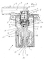
- An inventive venting valve referred to here briefly with valve 1, comprises an example cylindrical housing 2, on the underside of a bottom 3 is formed and which is closed at its top with a cover 4.
- the lid 4 has at an approximately central position a nozzle 5, which defines a ventilation opening 6.
- the housing 2 projects through a tank opening into the interior of the tank.
- the flange 7 has a connection 8, with which a ventilation line can be connected.
- the connection 8 is penetrated by a ventilation channel 9 which communicates with the ventilation opening 6.
- a gas-tight seal between the nozzle 5 of the lid 4 and the flange 7 is achieved via an O-ring 10, which rests in a circumferential groove 11 of the nozzle 5.
- an approximately cylindrical peripheral wall (12a) exhibiting cage 12 is formed, which is open on the underside and receives a sealing device 13 (or 70 in the case of FIGS. 8-11) axially movable.
- the sealing device 13 (also 70) is connected to a float 14, which is movable in the direction of the central longitudinal axis 15 of the housing 2.
- the float 14 is hollow inside and has a central, extending to about its lower end pin 16 which is held axially movable in a guide sleeve 17.
- the guide sleeve 17 is integrally formed on the bottom 3, wherein its interior communicates via an opening 18 in the bottom with the tank interior.
- a helical compression spring 20 is arranged, which acts on the float 14 with an upward, ie directed to the vent opening 6 towards force.
- the float 14 has an upper longitudinal section 22 of reduced diameter.
- a radially outwardly projecting flange 23 is formed, the underside of which has an approximately in a radial plane (radially with respect to the central longitudinal axis 15) extending stop surface 24.
- a central recess 25 In the end face 26 of the longitudinal section 22 there is a central recess 25, from the bottom of which a pin 27 arranged coaxially to the central longitudinal axis 15 extends away in the axial direction.
- the pin 25 ends with axial distance in front of the end face 26 of the longitudinal section 22.
- the recess 25 is due to the presence of the pin 27 in cross section and in plan view from above seen annular.
- a sealing element 28 is arranged in the recess 25, a sealing element 28 is arranged.
- This is formed by an example circular disk-shaped plate 29 and a plurality of webs 30.
- the webs 30 are arranged on the underside or on the side facing away from the ventilation opening 6 of the plate 29 and are distributed uniformly over the circumference thereof.
- the webs 30 are radially widened and project beyond the edge 31 of the plate 29 to some extent.
- the webs 30 are arranged in the annular recess 25.
- the plate 29 rests with the underside on the pin 27.
- the webs 30 project into a respective window 32 (FIG. 4) in the longitudinal section 22.
- the windows 32 extend in the direction the central longitudinal axis 15, whereby a certain axial mobility of the sealing element 28 is given.
- the webs 30 have an approximately in a radial plane extending abutment surface 33 which cooperates with the upper edge region 34 (Fig. 4) of a window 32 together.
- the sealing element 28 is further guided in the recess 25 with a certain radial clearance, so that the plate 29 with respect to the central longitudinal axis 15 can easily tilt or obliquely.
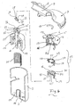
- the above-mentioned sealing device 13 which has a substantially circular outline, essentially consists of a lower carrier 36 and an upper carrier 37.
- the carriers 36, 37 are arranged one behind the other along the central longitudinal axis 15 and are in each case penetrated by a through-channel 35 or 48 extending coaxially to the central longitudinal axis 15.
- a coaxial with the central longitudinal axis 15 sealing element 45, 51, 57, 55 is arranged in each case.
- the carriers 36, 37 are each movable in the direction of the central longitudinal axis 15 of the valve housing 2 relative to each other and relative to the float by a predetermined distance between a closed position and an open position.
- the upper side designed as a planar sealing seat sealing member 51 on the lower side, in the form of a ring lip projecting sealing member 57 of the upper support 37 at.
- its upper-side sealing element 55 which is an annular lip protruding from the upper side of the support 37, cooperates with a sealing element 56 (FIG. 1) surrounding the ventilation opening 6 and designed as a flat sealing seat.
- the lower-side seal member 45 of the lower bracket 36 which has a protruding one Ring lip is cooperates with the present on the float 14 sealing element 28.
- Each two associated sealing elements 55/56, 51/57, 45/28 define an opening cross-section 61,62,63, wherein the size of the successive opening cross sections to the float 14 decreases towards.
- the opening cross section 62 (sealing element pair 55/56) is thus smaller than the opening cross section 61 (sealing element pair 51/57) and larger than the opening cross section 63 (sealing element pair 45/28).
- Said sealing element pairings 55/56, 51/57, 45/28 form the three stages of the valve.
- the lower support 36 is essentially formed by a circular disk 38 and a plurality of arms 39 distributed over its circumference and extending downwards from its edge 31 in the direction of the central longitudinal axis 15, shaped like circular arcuate wall sections. At the free ends of the arms 39 radially inwardly projecting projections 40 are integrally formed. For fixing the lower carrier 36, this is placed on the longitudinal portion 22 of the float 14, wherein the projections 40 with inclined surfaces 42 impinge on the flange 23 and are thereby moved radially outward. After the projections 40 have passed the flange 23, they move radially inward again. The projections 40 then cooperate with the stop surface 24 of the flange 23 in the sense of an axially effective undercut, whereby the carrier 36 is fixed with axial play on the longitudinal section 22.
- the total of three arms 39 are separated from each other in the circumferential direction by recesses 43 and evenly distributed in the circumferential direction.
- the circular disc 38 is penetrated centrally by a coaxial to the central longitudinal axis 15 extending through passage 35.
- An inner to the passageway 35th Adjacent region 44 (FIG. 2) of the circular disc 38 is made of elastomeric material. This protrudes on the underside of the circular disc 38 in the form of the funnel-shaped opening sealing element 45.
- the cross-sectional area of the passageway 35 is substantially smaller than the cross-sectional area of the venting aperture 6.
- the axial length of the arms 39 and the axial position of the projections 40 thereon are selected such that the lower support 36 is axially movable on the float or longitudinal portion 22 thereof is held.
- the sealing element 28 can be removed from the sealing element 45 of the carrier 36, whereby the opening cross-section 63 is released.
- a substantially pipe-section-shaped part 46 is inserted into the circular disk 38, which delimits the upper longitudinal section of the through-channel 35 and on the upper end side of which a radially extending flange 47 is formed, which rests on the upper side of the circular disk 38.
- the upper side of the flange 47 forms the sealing element 51 which cooperates with the sealing element 57 of the upper support 37.
- the upper carrier 37 is essentially formed by a circular ring 49, on the underside of which the arms 50, which extend axially or in the direction of the central longitudinal axis 15 and which are likewise designed in the manner of circular arcuate wall sections, are formed.
- the arms 50 are distributed uniformly over the circumference of the circular ring 49.
- projections 52 are formed, which protrude radially inwards. The projections 52 engage behind a stop surface 64 pointing towards the float 14 (FIG. 2) on the underside of the lower carrier 36.
- a region 65 of a carrier which carries a stop surface 64 or is set back from a projection is advantageous for a region 65 of a carrier which carries a stop surface 64 or is set back from a projection to be set back radially inwards at least by an amount corresponding to the thickness of an arm.
- this is accomplished by providing upwardly opening windows 53 in the arms 39 of the lower support 36, in each of which an arm 50 of the upper support 37 can be pushed at least partially into it.
- the length of the arms 50 and the axial position of the projections 52 are dimensioned in the axial direction so that the second carrier 37 is fixed axially movably on the first carrier 36.
- the annulus 49 carries an elastomeric element 54 which is substantially formed as a funnel opening to the vent opening 6, wherein the upper, axially beyond the circular ring 49 protruding edge forms the sealing element 55, which cooperates with the ventilation opening 6 bounding sealing element 56.
- the lower edge of the elastomer element 54, which forms the sealing element 57, also widens in a funnel shape and projects out of the underside of the carrier 37.
- the fixation of the sealing device 13 in the cage 12 with axial mobility is accomplished by engaging on the first support radially outwardly projecting locking projections 58 in windows 59, which are present in the cage 12, and in each case with the lower edge 66 (FIG Window 59 interact.
- the latching projections 58 are arranged on wall regions 60 of the first carrier 36, which connect two circumferentially adjacent arms 39 together.
- the valve described above or its sealing device 13 is designed in 3 stages. There are, of course, more than 3 stages, about 4, 5 or more conceivable, which are realized for example in the manner described above. By increasing the number of stages, a continuous opening of the ventilation opening can be achieved, i. the pressure differentials between the individual stages are the lower the more stages there are.
- the ventilation opening 6 is closed when the float 14 moves upwards, for instance due to an increasing fuel level.
- the weight of the float 14 is sufficient to move the sealing device 13 axially downward overall, whereby the ventilation opening 6 is released.
- an internal tank pressure builds up during the closure of the ventilation opening 6, the multiple stages of the sealing device 13 or of the valve 1 come into play.
- the float 14 rests with its flange 23 on the projections 40 of the lower support 36, so that it is loaded with the weight of the float.
- the force exerted by the weight of the float 14 on the lower support 36 is sufficient to move it axially downward, whereby the opening cross-section 62 is released. Now, a much larger gas flow leave the tank interior via the passage 48 and the vent opening 6.
- FIGS. 8 to 11 show a sealing device 70 which can be inserted in a valve of the type described above.
- the sealing device 70 is four-stage, it comprises a total of three carriers, namely an upper support 71, a central support 72 arranged therebelow and finally a lower support 73 arranged thereunder.
- the upper support 71 has a configuration that of that of the upper support 37 corresponds to the embodiment described above.
- the existing on the arms 50 projections 52 engage behind an underside of the central support 72 existing abutment surface 67. Accordingly, the same or equivalent parts are provided with the same reference numerals.
- the central carrier 72 is designed approximately disc-shaped and is penetrated by a central, coaxial with the central longitudinal axis 15 of the valve 1 and the sealing device 70 extending through passage 74.
- the diameter of the through-channel 74 is smaller than the smallest diameter of the through-channel 48 of the upper carrier 71.
- the middle carrier 72 comprises marginal, ie a radial distance to the central longitudinal axis 15 and a distance in the circumferential direction, formed approximately in the manner of circular arc-shaped wall segments arms 75 at whose free ends in each case a radially inwardly projecting projection 76 is present, which engages behind an underside of the lower carrier 73 existing abutment surface 77 (FIG.
- the arms 75 have an upwardly opening window 78, therefore, as the side view acc. Fig. 9 and 10 can be removed, U-shaped.
- the lower carrier 73 is designed similar to the middle carrier 72. Its three circumferentially uniformly distributed arms 79 are provided at their free ends with a radially inwardly projecting projection 80 which engages behind the flange 23 of the float 14 in the assembled state. In the arms 79 are upwardly opening window 82 available. On the outside, a projection 82 bridging the window 82 is integrally formed on the arms 79, which protrudes in the assembled state into a window 59 present in the cage 12 and cooperates with the lower edge 66 (FIG. 4, 7) of this window in the sense of a stop.
- the extent to which the areas 85, 86 are offset radially inwards corresponds approximately to The advantage of this embodiment is that the sealing device 70 as well as the sealing device 13 described above has a small width or a small outer circumference and accordingly requires a small installation space.
- the upper-side sealing element 86 of the middle carrier 72 cooperating with the lower-side sealing element 57 of the upper carrier 71 is formed by a region of the upper side of the carrier 72 which bounds the through-channel 74 or its upper-side mouth opening.
- an elastomer element 87 is arranged, which has a downwardly projecting, the passageway 74 and its lower side mouth opening bounding edge which forms a sealing element 88.
- the sealing element 88 cooperates with an upper-side sealing element 89 of the lower carrier 73.
- the sealing element 89 is formed by a surface region which delimits the central through-passage 90 of the lower support 73 or its upper-side orifice.
- the cooperating sealing elements 55/56, 57/86, 88/89 and 93/28 respectively include opening sections 61 and 94 to 96, the size of which decreases in the direction of the float 14.
- the operation of a valve equipped with the sealing device 70 corresponds to that of the three-stage valve described above, except that it is optimized due to the additional stage, in particular with regard to a rapid reopening after occurrence of an internal tank pressure.
Landscapes
- Engineering & Computer Science (AREA)
- General Engineering & Computer Science (AREA)
- Mechanical Engineering (AREA)
- Life Sciences & Earth Sciences (AREA)
- Sustainable Development (AREA)
- Sustainable Energy (AREA)
- Chemical & Material Sciences (AREA)
- Combustion & Propulsion (AREA)
- Transportation (AREA)
- Self-Closing Valves And Venting Or Aerating Valves (AREA)
Applications Claiming Priority (1)
| Application Number | Priority Date | Filing Date | Title |
|---|---|---|---|
| DE102006048183 | 2006-10-10 |
Publications (3)
| Publication Number | Publication Date |
|---|---|
| EP1912002A2 true EP1912002A2 (fr) | 2008-04-16 |
| EP1912002A3 EP1912002A3 (fr) | 2010-01-20 |
| EP1912002B1 EP1912002B1 (fr) | 2011-01-19 |
Family
ID=38925523
Family Applications (1)
| Application Number | Title | Priority Date | Filing Date |
|---|---|---|---|
| EP20070019827 Ceased EP1912002B1 (fr) | 2006-10-10 | 2007-10-10 | Soupape de purge d'air pour le réservoir de carburant d'un véhicule automobile |
Country Status (3)
| Country | Link |
|---|---|
| US (1) | US8001991B2 (fr) |
| EP (1) | EP1912002B1 (fr) |
| DE (1) | DE502007006294D1 (fr) |
Families Citing this family (10)
| Publication number | Priority date | Publication date | Assignee | Title |
|---|---|---|---|---|
| KR20140051133A (ko) * | 2011-01-21 | 2014-04-30 | 이턴 코포레이션 | 고압 적용을 위한 통합 플로트 밸브를 갖춘 차폐 밸브 |
| US9365107B2 (en) * | 2012-08-31 | 2016-06-14 | Stant Usa Corp. | Fuel tank vent apparatus |
| US9784381B2 (en) | 2013-05-24 | 2017-10-10 | Eaton Corporation | Balanced poppet float vent valve |
| KR101784622B1 (ko) * | 2016-08-18 | 2017-10-11 | 주식회사 니프코코리아 | 연료탱크용 과충전 방지 도출밸브 |
| JP2020050174A (ja) * | 2018-09-27 | 2020-04-02 | 京三電機株式会社 | 燃料タンク通気弁 |
| US10962131B2 (en) * | 2019-08-27 | 2021-03-30 | Toyoda Gosei Co., Ltd. | Fill limit vent valve |
| JP7198796B2 (ja) * | 2020-09-23 | 2023-01-04 | 本田技研工業株式会社 | 燃料ポンプユニットカバー及びその取付方法 |
| EP4253807A4 (fr) * | 2020-11-26 | 2024-10-09 | Yingzhi Aiyi Intelligent Automotive Technologies (Jiaxing) Co., Ltd. | Structure d'étanchéité de corps de soupape, soupape et soupape cflvv |
| US20230025882A1 (en) * | 2021-07-23 | 2023-01-26 | Toyoda Gosei Co., Ltd. | Fluid limit vent valve with splash prevention |
| CN113700917B (zh) * | 2021-08-18 | 2025-07-22 | 盈智皑壹智能汽车科技(嘉兴)有限公司 | 一种油箱排气阀 |
Family Cites Families (5)
| Publication number | Priority date | Publication date | Assignee | Title |
|---|---|---|---|---|
| US5511577A (en) * | 1994-03-02 | 1996-04-30 | Mulric Hydro Projects (Proprietary) Limited | Air release valve |
| US5590697A (en) | 1994-08-24 | 1997-01-07 | G. T. Products, Inc. | Onboard vapor recovery system with two-stage shutoff valve |
| US5605175A (en) * | 1995-05-24 | 1997-02-25 | Bergsma; Rudolph | Fluid responsive vent control valve with peel-away opening action |
| US6918405B2 (en) | 2003-12-04 | 2005-07-19 | Alfmeier Corporation | Fill limit vent valve |
| US7147017B2 (en) * | 2004-06-28 | 2006-12-12 | Alfmeier Corporation | Fill limit vent valve assembly |
-
2007
- 2007-10-10 DE DE200750006294 patent/DE502007006294D1/de active Active
- 2007-10-10 US US11/869,846 patent/US8001991B2/en not_active Expired - Fee Related
- 2007-10-10 EP EP20070019827 patent/EP1912002B1/fr not_active Ceased
Non-Patent Citations (1)
| Title |
|---|
| None |
Also Published As
| Publication number | Publication date |
|---|---|
| EP1912002A3 (fr) | 2010-01-20 |
| US8001991B2 (en) | 2011-08-23 |
| EP1912002B1 (fr) | 2011-01-19 |
| US20080092962A1 (en) | 2008-04-24 |
| DE502007006294D1 (de) | 2011-03-03 |
Similar Documents
| Publication | Publication Date | Title |
|---|---|---|
| EP1912002B1 (fr) | Soupape de purge d'air pour le réservoir de carburant d'un véhicule automobile | |
| EP1485309B1 (fr) | Soupape | |
| DE69636974T2 (de) | Ventileinheit zum einlass und auslass von flüssigkeiten | |
| DE102008019224B4 (de) | Ventilanordnung für einen unter Druck stehenden Fluidbehälter | |
| EP1291563B1 (fr) | Soupape non-retour et vanne avec une telle soupape non-retour | |
| DE60310346T2 (de) | Verschlussstopfen für eine Öffnung in einem Bauteil | |
| EP2028131A2 (fr) | Soupape en matière solide | |
| EP1555154A1 (fr) | Tubulure de remplissage pour le remplissage de combustible dans un réservoir d'un véhicule | |
| EP1207969A1 (fr) | Dispositif de purge dans le cas du piston d'une cartouche | |
| DE2234248A1 (de) | Wasserspender fuer tiere | |
| DE102007026543A1 (de) | Entwässerungsstopfen | |
| DE69807273T2 (de) | Überdruckventil | |
| WO2016066599A1 (fr) | Couvercle de canal de refroidissement et piston pourvu d'un couvercle de canal de refroidissement | |
| DE202015103420U1 (de) | Getriebesteuervorrichtung | |
| DE102013010598A1 (de) | Verschlussstopfen für eine Öffnung in einer Karosseriestruktur eines Automobils | |
| EP3748207B1 (fr) | Cartouche de soupape pour une armature sanitaire | |
| DE2349772C2 (de) | Absperrorgan | |
| DE7414600U (de) | Elektrisches differentialventil zur fluessigkeitssteuerung | |
| WO2018086831A1 (fr) | Tête de distribution à auto-fermeture | |
| DE10308669A1 (de) | Entwässerungsanordnung für einen Karosseriehohlraum | |
| DE102007026544A1 (de) | Verschlussstopfen | |
| DE102009040832B4 (de) | Vorrichtung zum Öffnen und Verschließen eines Getränkebehälters, bei welcher der Deckel mit einer Deckelbasis und einem Ventilschieber verbunden ist | |
| DE2639571A1 (de) | Freigabeventil | |
| EP1887267B1 (fr) | Cartouche de mélangeur | |
| DE3232178A1 (de) | Verschlussdeckel |
Legal Events
| Date | Code | Title | Description |
|---|---|---|---|
| PUAI | Public reference made under article 153(3) epc to a published international application that has entered the european phase |
Free format text: ORIGINAL CODE: 0009012 |
|
| AK | Designated contracting states |
Kind code of ref document: A2 Designated state(s): AT BE BG CH CY CZ DE DK EE ES FI FR GB GR HU IE IS IT LI LT LU LV MC MT NL PL PT RO SE SI SK TR |
|
| AX | Request for extension of the european patent |
Extension state: AL BA HR MK RS |
|
| PUAL | Search report despatched |
Free format text: ORIGINAL CODE: 0009013 |
|
| AK | Designated contracting states |
Kind code of ref document: A3 Designated state(s): AT BE BG CH CY CZ DE DK EE ES FI FR GB GR HU IE IS IT LI LT LU LV MC MT NL PL PT RO SE SI SK TR |
|
| AX | Request for extension of the european patent |
Extension state: AL BA HR MK RS |
|
| RIC1 | Information provided on ipc code assigned before grant |
Ipc: B60K 15/035 20060101ALI20091215BHEP Ipc: F16K 24/04 20060101AFI20080122BHEP |
|
| 17P | Request for examination filed |
Effective date: 20100219 |
|
| GRAP | Despatch of communication of intention to grant a patent |
Free format text: ORIGINAL CODE: EPIDOSNIGR1 |
|
| AKX | Designation fees paid |
Designated state(s): DE FR |
|
| GRAS | Grant fee paid |
Free format text: ORIGINAL CODE: EPIDOSNIGR3 |
|
| GRAA | (expected) grant |
Free format text: ORIGINAL CODE: 0009210 |
|
| AK | Designated contracting states |
Kind code of ref document: B1 Designated state(s): DE FR |
|
| REF | Corresponds to: |
Ref document number: 502007006294 Country of ref document: DE Date of ref document: 20110303 Kind code of ref document: P |
|
| REG | Reference to a national code |
Ref country code: DE Ref legal event code: R096 Ref document number: 502007006294 Country of ref document: DE Effective date: 20110303 |
|
| PLBE | No opposition filed within time limit |
Free format text: ORIGINAL CODE: 0009261 |
|
| STAA | Information on the status of an ep patent application or granted ep patent |
Free format text: STATUS: NO OPPOSITION FILED WITHIN TIME LIMIT |
|
| 26N | No opposition filed |
Effective date: 20111020 |
|
| REG | Reference to a national code |
Ref country code: DE Ref legal event code: R097 Ref document number: 502007006294 Country of ref document: DE Effective date: 20111020 |
|
| REG | Reference to a national code |
Ref country code: DE Ref legal event code: R082 Ref document number: 502007006294 Country of ref document: DE Representative=s name: MEISSNER BOLTE & PARTNER GBR, DE Ref country code: DE Ref legal event code: R082 Ref document number: 502007006294 Country of ref document: DE Representative=s name: MEISSNER BOLTE PATENTANWAELTE RECHTSANWAELTE P, DE |
|
| REG | Reference to a national code |
Ref country code: FR Ref legal event code: PLFP Year of fee payment: 9 |
|
| REG | Reference to a national code |
Ref country code: DE Ref legal event code: R082 Ref document number: 502007006294 Country of ref document: DE Representative=s name: MEISSNER BOLTE PATENTANWAELTE RECHTSANWAELTE P, DE |
|
| REG | Reference to a national code |
Ref country code: FR Ref legal event code: PLFP Year of fee payment: 10 |
|
| REG | Reference to a national code |
Ref country code: FR Ref legal event code: PLFP Year of fee payment: 11 |
|
| REG | Reference to a national code |
Ref country code: FR Ref legal event code: PLFP Year of fee payment: 12 |
|
| PGFP | Annual fee paid to national office [announced via postgrant information from national office to epo] |
Ref country code: DE Payment date: 20191023 Year of fee payment: 13 |
|
| REG | Reference to a national code |
Ref country code: DE Ref legal event code: R119 Ref document number: 502007006294 Country of ref document: DE |
|
| PG25 | Lapsed in a contracting state [announced via postgrant information from national office to epo] |
Ref country code: DE Free format text: LAPSE BECAUSE OF NON-PAYMENT OF DUE FEES Effective date: 20210501 |
|
| PGFP | Annual fee paid to national office [announced via postgrant information from national office to epo] |
Ref country code: FR Payment date: 20231023 Year of fee payment: 17 |
|
| PG25 | Lapsed in a contracting state [announced via postgrant information from national office to epo] |
Ref country code: FR Free format text: LAPSE BECAUSE OF NON-PAYMENT OF DUE FEES Effective date: 20241031 |