EP1912200A2 - Dispositif de conduite d'une unité de rétroéclairage, appareil d'affichage à cristaux liquides l'utilisant et son procédé de contrôle - Google Patents
Dispositif de conduite d'une unité de rétroéclairage, appareil d'affichage à cristaux liquides l'utilisant et son procédé de contrôle Download PDFInfo
- Publication number
- EP1912200A2 EP1912200A2 EP07116064A EP07116064A EP1912200A2 EP 1912200 A2 EP1912200 A2 EP 1912200A2 EP 07116064 A EP07116064 A EP 07116064A EP 07116064 A EP07116064 A EP 07116064A EP 1912200 A2 EP1912200 A2 EP 1912200A2
- Authority
- EP
- European Patent Office
- Prior art keywords
- unit
- temperature
- light source
- heating device
- driving
- Prior art date
- Legal status (The legal status is an assumption and is not a legal conclusion. Google has not performed a legal analysis and makes no representation as to the accuracy of the status listed.)
- Withdrawn
Links
Images


Classifications
-
- H—ELECTRICITY
- H05—ELECTRIC TECHNIQUES NOT OTHERWISE PROVIDED FOR
- H05B—ELECTRIC HEATING; ELECTRIC LIGHT SOURCES NOT OTHERWISE PROVIDED FOR; CIRCUIT ARRANGEMENTS FOR ELECTRIC LIGHT SOURCES, IN GENERAL
- H05B41/00—Circuit arrangements or apparatus for igniting or operating discharge lamps
- H05B41/14—Circuit arrangements
- H05B41/26—Circuit arrangements in which the lamp is fed by power derived from DC by means of a converter, e.g. by high-voltage DC
- H05B41/28—Circuit arrangements in which the lamp is fed by power derived from DC by means of a converter, e.g. by high-voltage DC using static converters
- H05B41/282—Circuit arrangements in which the lamp is fed by power derived from DC by means of a converter, e.g. by high-voltage DC using static converters with semiconductor devices
- H05B41/285—Arrangements for protecting lamps or circuits against abnormal operating conditions
-
- G—PHYSICS
- G02—OPTICS
- G02F—OPTICAL DEVICES OR ARRANGEMENTS FOR THE CONTROL OF LIGHT BY MODIFICATION OF THE OPTICAL PROPERTIES OF THE MEDIA OF THE ELEMENTS INVOLVED THEREIN; NON-LINEAR OPTICS; FREQUENCY-CHANGING OF LIGHT; OPTICAL LOGIC ELEMENTS; OPTICAL ANALOGUE/DIGITAL CONVERTERS
- G02F1/00—Devices or arrangements for the control of the intensity, colour, phase, polarisation or direction of light arriving from an independent light source, e.g. switching, gating or modulating; Non-linear optics
- G02F1/01—Devices or arrangements for the control of the intensity, colour, phase, polarisation or direction of light arriving from an independent light source, e.g. switching, gating or modulating; Non-linear optics for the control of the intensity, phase, polarisation or colour
- G02F1/13—Devices or arrangements for the control of the intensity, colour, phase, polarisation or direction of light arriving from an independent light source, e.g. switching, gating or modulating; Non-linear optics for the control of the intensity, phase, polarisation or colour based on liquid crystals, e.g. single liquid crystal display cells
- G02F1/133—Constructional arrangements; Operation of liquid crystal cells; Circuit arrangements
-
- G—PHYSICS
- G02—OPTICS
- G02F—OPTICAL DEVICES OR ARRANGEMENTS FOR THE CONTROL OF LIGHT BY MODIFICATION OF THE OPTICAL PROPERTIES OF THE MEDIA OF THE ELEMENTS INVOLVED THEREIN; NON-LINEAR OPTICS; FREQUENCY-CHANGING OF LIGHT; OPTICAL LOGIC ELEMENTS; OPTICAL ANALOGUE/DIGITAL CONVERTERS
- G02F1/00—Devices or arrangements for the control of the intensity, colour, phase, polarisation or direction of light arriving from an independent light source, e.g. switching, gating or modulating; Non-linear optics
- G02F1/01—Devices or arrangements for the control of the intensity, colour, phase, polarisation or direction of light arriving from an independent light source, e.g. switching, gating or modulating; Non-linear optics for the control of the intensity, phase, polarisation or colour
- G02F1/13—Devices or arrangements for the control of the intensity, colour, phase, polarisation or direction of light arriving from an independent light source, e.g. switching, gating or modulating; Non-linear optics for the control of the intensity, phase, polarisation or colour based on liquid crystals, e.g. single liquid crystal display cells
- G02F1/133—Constructional arrangements; Operation of liquid crystal cells; Circuit arrangements
- G02F1/1333—Constructional arrangements; Manufacturing methods
- G02F1/1335—Structural association of cells with optical devices, e.g. polarisers or reflectors
-
- G—PHYSICS
- G09—EDUCATION; CRYPTOGRAPHY; DISPLAY; ADVERTISING; SEALS
- G09G—ARRANGEMENTS OR CIRCUITS FOR CONTROL OF INDICATING DEVICES USING STATIC MEANS TO PRESENT VARIABLE INFORMATION
- G09G3/00—Control arrangements or circuits, of interest only in connection with visual indicators other than cathode-ray tubes
- G09G3/20—Control arrangements or circuits, of interest only in connection with visual indicators other than cathode-ray tubes for presentation of an assembly of a number of characters, e.g. a page, by composing the assembly by combination of individual elements arranged in a matrix no fixed position being assigned to or needed to be assigned to the individual characters or partial characters
- G09G3/34—Control arrangements or circuits, of interest only in connection with visual indicators other than cathode-ray tubes for presentation of an assembly of a number of characters, e.g. a page, by composing the assembly by combination of individual elements arranged in a matrix no fixed position being assigned to or needed to be assigned to the individual characters or partial characters by control of light from an independent source
- G09G3/3406—Control of illumination source
-
- G—PHYSICS
- G02—OPTICS
- G02F—OPTICAL DEVICES OR ARRANGEMENTS FOR THE CONTROL OF LIGHT BY MODIFICATION OF THE OPTICAL PROPERTIES OF THE MEDIA OF THE ELEMENTS INVOLVED THEREIN; NON-LINEAR OPTICS; FREQUENCY-CHANGING OF LIGHT; OPTICAL LOGIC ELEMENTS; OPTICAL ANALOGUE/DIGITAL CONVERTERS
- G02F1/00—Devices or arrangements for the control of the intensity, colour, phase, polarisation or direction of light arriving from an independent light source, e.g. switching, gating or modulating; Non-linear optics
- G02F1/01—Devices or arrangements for the control of the intensity, colour, phase, polarisation or direction of light arriving from an independent light source, e.g. switching, gating or modulating; Non-linear optics for the control of the intensity, phase, polarisation or colour
- G02F1/13—Devices or arrangements for the control of the intensity, colour, phase, polarisation or direction of light arriving from an independent light source, e.g. switching, gating or modulating; Non-linear optics for the control of the intensity, phase, polarisation or colour based on liquid crystals, e.g. single liquid crystal display cells
- G02F1/133—Constructional arrangements; Operation of liquid crystal cells; Circuit arrangements
- G02F1/1333—Constructional arrangements; Manufacturing methods
- G02F1/1335—Structural association of cells with optical devices, e.g. polarisers or reflectors
- G02F1/1336—Illuminating devices
- G02F1/133602—Direct backlight
- G02F1/133604—Direct backlight with lamps
-
- G—PHYSICS
- G02—OPTICS
- G02F—OPTICAL DEVICES OR ARRANGEMENTS FOR THE CONTROL OF LIGHT BY MODIFICATION OF THE OPTICAL PROPERTIES OF THE MEDIA OF THE ELEMENTS INVOLVED THEREIN; NON-LINEAR OPTICS; FREQUENCY-CHANGING OF LIGHT; OPTICAL LOGIC ELEMENTS; OPTICAL ANALOGUE/DIGITAL CONVERTERS
- G02F1/00—Devices or arrangements for the control of the intensity, colour, phase, polarisation or direction of light arriving from an independent light source, e.g. switching, gating or modulating; Non-linear optics
- G02F1/01—Devices or arrangements for the control of the intensity, colour, phase, polarisation or direction of light arriving from an independent light source, e.g. switching, gating or modulating; Non-linear optics for the control of the intensity, phase, polarisation or colour
- G02F1/13—Devices or arrangements for the control of the intensity, colour, phase, polarisation or direction of light arriving from an independent light source, e.g. switching, gating or modulating; Non-linear optics for the control of the intensity, phase, polarisation or colour based on liquid crystals, e.g. single liquid crystal display cells
- G02F1/133—Constructional arrangements; Operation of liquid crystal cells; Circuit arrangements
- G02F1/1333—Constructional arrangements; Manufacturing methods
- G02F1/1335—Structural association of cells with optical devices, e.g. polarisers or reflectors
- G02F1/1336—Illuminating devices
- G02F1/133602—Direct backlight
- G02F1/133612—Electrical details
-
- G—PHYSICS
- G09—EDUCATION; CRYPTOGRAPHY; DISPLAY; ADVERTISING; SEALS
- G09G—ARRANGEMENTS OR CIRCUITS FOR CONTROL OF INDICATING DEVICES USING STATIC MEANS TO PRESENT VARIABLE INFORMATION
- G09G2320/00—Control of display operating conditions
- G09G2320/04—Maintaining the quality of display appearance
- G09G2320/041—Temperature compensation
Definitions
- Apparatuses and methods consistent with the present invention relate to a driving device of a backlight unit, a liquid crystal display (LCD) having the same and a control method thereof, and more particularly to a driving device of a backlight unit, an LCD apparatus having the same and a control method thereof which can rapidly stabilize brightness of a light source according to temperature of a light source unit.
- LCD liquid crystal display
- An LCD apparatus comprises an LCD panel.
- the LCD panel comprises a thin film transistor (TFT) substrate, a color filter substrate, and a liquid crystal injected between the TFT substrate and the color filter substrate. Since the LCD panel does not emit light by itself, a backlight unit may be provided at the backside of the TFT substrate to provide light. The penetration amount of an incident light provided by the backlight unit is adjusted according to an alignment of the liquid crystal.
- TFT thin film transistor
- the backlight unit may be classified into an edge-type and a direct-type.
- a light source such as a cold cathode fluorescent lamp (CCFL) and others known in the art is disposed at a lateral side of a light guide plate, and a collection/diffusion sheet is disposed at an upper side of the light guide plate.
- CCFL cold cathode fluorescent lamp
- the direct-type backlight unit a plurality of light sources is disposed at the backside of the LCD panel, and a collection/diffusion film is disposed between the light source and the LCD panel.
- flat fluorescent lamp FLC is a planar application of the CCFL theory, and has a structure that a fluorescent layer and a light emitting gas which are sealed between two plane glasses.
- the FFL requires more time than the CCFL to stabilize brightness.
- the FFL is designed to preheat a lamp for a predetermined time using a heating wire before FFL is turned on so that the brightness can be rapidly stabilized.
- a constant voltage is used as a driving voltage to heat the heating wire.
- the heating wire always emits the same calorific value in spite of variable temperature of the lamp. Therefore, a deviation in the temperature of the lamp occurs to influence stability of the brightness.
- Another aspect of the present invention is to provide a driving device of a backlight unit, an LCD apparatus having the same and a control method thereof which can adjust calorific value generated by a heating device according to the temperature of the light source unit to decrease deviation in the temperature of the light source unit.
- an LCD apparatus comprising: an LCD panel; a light source unit which emits light to the LCD panel; a heating device which preheats the light source unit; a temperature sensing unit which senses temperature of the light source unit and outputs a temperature information; and a variable voltage supplying unit which changes a driving voltage to be supplied to the heating device according to the temperature information of the temperature sensing unit.
- the temperature sensing unit is a resistance device whose resistance value changes according to temperature change.
- the resistance device is a thermistor.
- the thermistor has a negative temperature coefficient (NTC).
- variable voltage supplying unit changes the driving voltage supplied to the heating device by voltage change according to change of resistance value of the resistance device.
- variable voltage supplying unit comprises an operational amplifier to change the driving voltage supplied to the heating device according to the change of the resistance value of the resistance device.
- variable voltage supplying unit further comprises a Zener diode connected to an input terminal of the operational amplifier to receive a predetermined reference voltage.
- the LCD apparatus further comprises: a switching unit which supplies a predetermined input voltage to the variable voltage supplying unit; and a control unit which outputs a control signal to turn off the switching unit if the temperature information of the temperature sensing unit exceeds a predetermined temperature.
- the heating device is a heating wire.
- the light source unit is a surface light source lamp.
- the LCD apparatus further comprises a light source driving inverter which drives the light source unit.
- a driving device of backlight unit for driving a backlight unit having a light source unit and a heating device to preheat the light source unit, comprising: a temperature sensing unit which senses temperature of the light source unit and outputs temperature information; and a variable voltage supplying unit which changes a driving voltage supplied to the heating device according to the temperature information of the temperature sensing unit.
- the temperature sensing unit is a resistance device whose resistance value changes according to temperature change.
- the resistance device is a thermistor having an NTC.
- variable voltage supplying unit changes the driving voltage supplied to the heating device by voltage change according to change of resistance value of the resistance device.
- variable voltage supplying unit comprises an operational amplifier to change the driving voltage supplied to the heating device according to the change of the resistance value of the resistance device.
- the driving device of backlight unit further comprises: a switching unit which supplies a predetermined input voltage to the variable voltage supplying unit; and a control unit which outputs a control signal to turn off the switching unit if the temperature information of the temperature sensing unit exceeds a predetermined temperature.
- the heating device is a heating wire.
- the light source unit is a surface light source lamp.
- a control method of an LCD apparatus comprising an LCD panel, a light source unit to emit light to the LCD panel, and a heating device to preheat the light source unit, comprising: outputting a temperature information by a temperature sensing unit by sensing temperature of the light source unit; and changing a driving voltage supplied to the heating device according to the temperature information of the temperature sensing unit.
- the temperature sensing unit is a resistance device whose resistance value changes according to temperature change.
- changing a driving voltage comprises changing the driving voltage supplied to the heating device by voltage change according to change of the resistance value of the resistance device.
- control method of an LCD apparatus further comprises cutting off the driving voltage supplied to the heating device if the temperature information exceeds a predetermined temperature.
- FIG. 1 is a block diagram illustrating a configuration of a liquid crystal display apparatus according to an exemplary embodiment of the present invention.
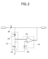
- FIG. 2 is a circuit diagram specifically describing a temperature sensing unit and a variable voltage supplying unit according to the exemplary embodiment of the present invention.
- FIG. 3 is a flow diagram illustrating control process of the LCD apparatus according to an exemplary embodiment of the present invention.
- an LCD apparatus 100 comprises a power supply unit 110, a backlight unit 120, a heating device driving unit 130, a control unit 140, and a key input unit 150.
- the power supply unit 110 generates a predetermined DC voltage or AC voltage required for configuration of the control unit 140 and the backlight unit 120 from a battery voltage or an input AC voltage.
- the generated predetermined voltage is supplied to a light source unit 122 of the backlight unit 120, the heating device driving unit 130, and the control unit 140.
- the light source unit 122 which emits light requires a large amount of electric power. Therefore, to drive the light source unit 122, the power supply unit 110 comprises a light source driving inverter 112.
- the backlight unit 120 is installed to emit light to an LCD panel (not shown), and comprises the light source unit 122 and a heating device 124.
- the light source unit 122 is a light source to supply light to the LCD panel, and is preferably but not necessarily a surface light source which comprises FFL. However, the light source unit 122 may also be a related art light source such as CCFL, or other related art lamp.
- the heating device 124 is for preheating the light source unit 122, and is preferably but not necessarily a heating wire.
- the heating device driving unit 130 is for controlling a calorific value of the heating device 124, and comprises a temperature sensing unit 132, a variable voltage supplying unit 134, and a switching unit 136.
- the temperature sensing unit 132 senses temperature of the light source unit 122 or ambient temperature of the light source unit 122. As the temperature to be sensed by the temperature sensing unit 132 is related to the light source unit 122, the sensed temperature is hereinafter called the temperature of the light source unit 122.
- the temperature information sensed by the temperature sensing unit 132 is supplied to the variable voltage supplying unit 134 and the control unit 140.
- the variable voltage supplying unit 134 adjusts a driving voltage to be supplied to the heating device 124 according to the temperature information sensed by the temperature sensing unit 132. Therefore, the calorific value of the heating device 124 varies according to the supplied driving voltage.
- the switching unit 136 cuts off the voltage supplied to the variable voltage supplying unit 34. Especially, if the temperature information sensed by the temperature sensing unit 132 exceeds a predetermined temperature, the switching unit 136 is turned off by a control signal which is output by the control unit 140. Therefore, the brightness is prevented from being further unstable due to heating of the light source unit 122.
- the control unit 140 calculates the temperature of the light source unit 122 using the temperature information input by the temperature sensing unit 132. Then, if the temperature of the light source unit 122 exceeds a predetermined temperature or if the preheating time of the heating device 124 elapses beyond a predetermined time, the control unit 140 outputs a control signal to turn off the switching unit 136. The switching unit 136 cuts off the voltage supplied to the variable voltage supplying unit 134 by the control signal. Also, the control unit 140 sends a control signal to the light source driving inverter 112 to control intensity of the light to be emitted by the light source unit 122.
- the key input unit 150 receives a command by a user's key operation and supplies the command to the control unit 140.
- the key input unit 150 may comprise a number of keys attached to the LCD apparatus 100. Also, the key input unit 150 may be provided to receive command input by a remote control or others known in the art.
- control unit 140 senses turn-on status of the power button and controls the power supply unit 110 to operate so that the voltage to be supplied to the light source unit 122 and the variable voltage supplying unit 134 can be generated and output.
- control unit 140 controls the switch of the switching unit 136 to be turned on. Therefore, a predetermined voltage output by the power supply unit 110 is supplied to the variable voltage supplying unit 134.
- the temperature sensing unit 132 senses the temperature of the light source unit 122 and supplies the temperature information to the control unit 140. If the temperature information sensed by the temperature sensing unit 132 exceeds a predetermined temperature, the control unit 140 outputs the control signal to turn off the switching unit 136. Therefore, the brightness can be rapidly stabilized compared to a case of continuously heating the heating device 124 for a predetermined time by constant voltage.
- the temperature information sensed by the temperature sensing unit 132 is supplied to the variable voltage supplying unit 134. According to the temperature information, the variable voltage supplying unit 134 outputs an adjusted driving voltage to be supplied to the heating device 124. That is, if the temperature sensed by the temperature sensing unit 132 is high, the variable voltage supplying unit 134 outputs the driving voltage to be supplied to the heating device 124 with the driving voltage decreased compared to the sensed temperature being low.
- V is the driving voltage supplied to the heating device 124
- R is a resistance of the heating device 124. Accordingly, if the temperature is low, a high driving voltage is supplied to the heating device 124, so that the calorific value is increased. However, if the temperature becomes higher, a low driving voltage is supplied to the heating device 124, so that the calorific value is relatively decreased compared to the temperature being low.
- the temperature information sensed by the temperature sensing unit 132 is shown to be directly supplied to the variable voltage supplying unit 134.
- the variable voltage supplying unit 134 may be controlled to change the driving voltage supplied to the heating device 124 using the temperature information supplied to the control unit 140. That is, the control unit 140 may output the control signal or control voltage which corresponds to the temperature information, and the variable voltage supplying unit 134 may change and output the driving voltage to be supplied to the heating device 124 according to the control signal or control voltage.
- FIG. 2 is a circuit diagram specifically describing the temperature sensing unit 132 and the variable voltage supplying unit 134 shown in FIG. 1 according to the exemplary embodiment of the present invention.
- the temperature sensing unit 132 comprises a thermistor T 212 and a resistor R2 214.
- the thermistor T 212 is a resistance device whose resistance value changes according to its temperature, and is preferably but not necessarily a thermistor having an NTC.
- the variable voltage supplying unit 134 comprises a Zener diode Z 222 and an operational amplifier 224.
- the Zener diode Z 222 is connected to (+) input terminal of the operational amplifier 224 to supply a predetermined reference voltage to the operational amplifier 224. Since the operational amplifier 224 basically has an infinite voltage gain, a voltage input to (+) input terminal thereof becomes the same as a voltage input to (-) input terminal thereof. Also, since its input impedance is infinite, current in the input terminal becomes 0.
- Input voltage input through the switching unit 136 is supplied to the thermistor T 212 and the resistor R2 214 through the resistor R1 202. Nodes of the thermistor T 212 and the resistor R2 214 are connected to the (-) input terminal of the operational amplifier 224.
- the Zener diode Z 222 is connected to the (+) input terminal of the operational amplifier 224. Therefore, as the Zener diode Z 222 supplies the predetermined reference voltage to the (+) input terminal of the operational amplifier 224, the voltage of the (-) input terminal of the operational amplifier 224 becomes the same as a nominal voltage of the Zener diode Z 222.
- the constant-current flowing in the resistor R2 214 equally flows in the thermistor T 212. Therefore, if the resistance value of the thermistor T 212 changes according to temperature change, the driving voltage supplied to the heating device 124 changes. That is, if the temperature of the light source unit 122 rises, the resistance value of the thermistor T 212 decreases. Also, a voltage between both ends of the thermistor T 212, which is calculated by multiplying the resistance of the thermistor T 212 by the current flowing in the resistor R2 214, decreases, resulting in decrease of the driving voltage supplied to the heating device 124.
- FIG. 3 is a flow diagram to explain control process of the LCD apparatus according to an exemplary embodiment of the present invention.
- control unit 140 turns on the power supply unit 110 to generate and output the voltage to be supplied to the light source unit 122 and the variable voltage supplying unit 134.
- the temperature sensing unit 132 senses the temperature of the light source unit 122 to output the temperature information to the control unit 140 and the variable voltage supplying unit 134 at S304. If the temperature information sensed by the temperature sensing unit 132 exceeds a predetermined temperature at S306, the control unit 140 outputs the control signal to turn off the switching unit 136. As the switching unit 136 is turned off by the control signal, the driving voltage supplied to the heating device 124 is cut off at S312.
- the variable voltage supplying unit 134 changes and outputs the driving voltage supplied to the heating device 124 according to the temperature information at S308. That is, if the temperature sensed by the temperature sensing unit 132 is high, the variable voltage supplying unit 134 outputs the driving voltage to be supplied to the heating device 124 with the driving voltage decreased compared to the sensed temperature being low.
- the control unit 140 If the preheating time for supplying the driving voltage to the heating device 124 exceeds a predetermined preheating time at S310, the control unit 140 outputs the control signal to turn off the switching unit 136, and the switching unit 136 is turned off by the control signal. Therefore, the driving voltage supplied to the heating device 124 is cut off at S312.
- the brightness of the lamp can be rapidly stabilized according to the temperature of the light source unit.
- the deviation in the temperature of the lamp can be decreased by changing the calorific value generated by the heating device 124 according to the temperature of the light source unit 122.
- the voltage is cut off to save electric power and prevent overheating.
Landscapes
- Physics & Mathematics (AREA)
- Nonlinear Science (AREA)
- General Physics & Mathematics (AREA)
- Engineering & Computer Science (AREA)
- Mathematical Physics (AREA)
- Chemical & Material Sciences (AREA)
- Crystallography & Structural Chemistry (AREA)
- Optics & Photonics (AREA)
- Computer Hardware Design (AREA)
- Theoretical Computer Science (AREA)
- Liquid Crystal (AREA)
Applications Claiming Priority (1)
| Application Number | Priority Date | Filing Date | Title |
|---|---|---|---|
| KR1020060099916A KR20080033771A (ko) | 2006-10-13 | 2006-10-13 | 백라이트 유닛의 구동장치, 이를 구비한 액정표시장치, 및그 제어방법 |
Publications (2)
| Publication Number | Publication Date |
|---|---|
| EP1912200A2 true EP1912200A2 (fr) | 2008-04-16 |
| EP1912200A3 EP1912200A3 (fr) | 2010-04-28 |
Family
ID=38935827
Family Applications (1)
| Application Number | Title | Priority Date | Filing Date |
|---|---|---|---|
| EP07116064A Withdrawn EP1912200A3 (fr) | 2006-10-13 | 2007-09-11 | Dispositif de conduite d'une unité de rétroéclairage, appareil d'affichage à cristaux liquides l'utilisant et son procédé de contrôle |
Country Status (4)
| Country | Link |
|---|---|
| US (1) | US20080088554A1 (fr) |
| EP (1) | EP1912200A3 (fr) |
| KR (1) | KR20080033771A (fr) |
| CN (1) | CN101162564A (fr) |
Cited By (1)
| Publication number | Priority date | Publication date | Assignee | Title |
|---|---|---|---|---|
| CN102169672A (zh) * | 2011-03-19 | 2011-08-31 | 福州华映视讯有限公司 | 背光模块、过温度保护电路及其过温度保护方法 |
Families Citing this family (19)
| Publication number | Priority date | Publication date | Assignee | Title |
|---|---|---|---|---|
| BRPI0920123A2 (pt) * | 2008-10-14 | 2016-01-12 | Sharp Kk | dispositivo de monitor de cristal líquido |
| JP5310136B2 (ja) * | 2009-03-13 | 2013-10-09 | ソニー株式会社 | 液晶表示装置および液晶表示装置の電源オン時制御方法 |
| CN101995688B (zh) * | 2009-08-27 | 2012-12-19 | 厦门立林科技有限公司 | 可在低温工作的单色液晶显示模块 |
| KR101142702B1 (ko) | 2010-05-06 | 2012-05-03 | 삼성모바일디스플레이주식회사 | 유기전계발광표시장치 및 그의 구동방법 |
| US8536788B2 (en) * | 2010-08-06 | 2013-09-17 | Osram Sylvania Inc. | Thermal control of solid state light sources by variable series impedance |
| JP5208261B2 (ja) * | 2011-02-08 | 2013-06-12 | キヤノン株式会社 | バックライト装置及びその制御方法、画像表示装置 |
| US9128282B2 (en) | 2011-02-10 | 2015-09-08 | Seiko Epson Corporation | Head-mounted display device and control method for the head-mounted display device |
| CN103595232A (zh) * | 2012-08-14 | 2014-02-19 | 神讯电脑(昆山)有限公司 | 逆变器的温度保护电路 |
| CN103606363A (zh) * | 2013-12-04 | 2014-02-26 | 中航华东光电有限公司 | 基于fpga的lcd型头盔显示驱动电路 |
| CN103747597B (zh) * | 2014-01-26 | 2017-02-15 | 厦门市三安光电科技有限公司 | 白光照明系统及其控制方法 |
| KR101723714B1 (ko) * | 2014-10-24 | 2017-04-06 | 한국광기술원 | 발열 기능을 갖는 차량용 전조등 |
| EP3142097A1 (fr) | 2015-09-08 | 2017-03-15 | Canon Kabushiki Kaisha | Appareil d'excitation de cristaux liquides, appareil d'affichage d'image et programme d'excitation de cristaux liquides |
| JP6253622B2 (ja) * | 2015-09-08 | 2017-12-27 | キヤノン株式会社 | 液晶駆動装置、画像表示装置および液晶駆動プログラム |
| JP2017053950A (ja) | 2015-09-08 | 2017-03-16 | キヤノン株式会社 | 液晶駆動装置、画像表示装置および液晶駆動プログラム |
| JP6632275B2 (ja) | 2015-09-08 | 2020-01-22 | キヤノン株式会社 | 液晶駆動装置、画像表示装置および液晶駆動プログラム |
| EP3300653B1 (fr) * | 2016-09-30 | 2019-07-03 | Smart Eye AB | Suivi oculaire/de tête avec préchauffage de source lumineuse |
| CN113520176B (zh) * | 2021-07-21 | 2023-05-02 | 杭州老板电器股份有限公司 | 一种烤箱照明亮度的智能调节方法、智能调节装置、终端和计算机可读存储介质 |
| CN114299839B (zh) * | 2022-01-06 | 2024-04-30 | 苏州蓝石新动力有限公司 | 一种段码屏驱动系统与段码屏驱动方法 |
| CN117666217B (zh) * | 2024-02-01 | 2024-05-03 | 惠科股份有限公司 | 背光模组及显示装置 |
Family Cites Families (10)
| Publication number | Priority date | Publication date | Assignee | Title |
|---|---|---|---|---|
| JPS6236966A (ja) * | 1985-08-09 | 1987-02-17 | Casio Comput Co Ltd | 光源装置 |
| WO1995012964A1 (fr) * | 1993-11-03 | 1995-05-11 | Science Applications International Corporation | Systeme d'illumination uv par l'arriere a haute efficacite pour dispositifs d'affichage electroniques |
| US6269565B1 (en) * | 1994-11-28 | 2001-08-07 | Smartlight Ltd. | Display device |
| EP0733927B1 (fr) * | 1995-03-22 | 2001-11-07 | Canon Kabushiki Kaisha | Dispositif d'affichage produisant une distribution de température homogène sur l'écran |
| US6201352B1 (en) * | 1995-09-22 | 2001-03-13 | Gl Displays, Inc. | Cold cathode fluorescent display |
| JPH11219612A (ja) * | 1997-11-28 | 1999-08-10 | Toshiba Lighting & Technology Corp | バックライト及び表示装置 |
| JP3990167B2 (ja) * | 2002-03-04 | 2007-10-10 | Nec液晶テクノロジー株式会社 | 液晶表示装置の駆動方法およびその駆動方法を用いた液晶表示装置 |
| KR100953429B1 (ko) * | 2003-08-11 | 2010-04-20 | 삼성전자주식회사 | 램프 구동 방법 및 그 장치와, 이를 갖는 백라이트어셈블리 및 액정 표시 장치 |
| KR101133755B1 (ko) * | 2004-07-22 | 2012-04-09 | 삼성전자주식회사 | 표시 장치 및 표시 장치용 광원의 구동 장치 |
| KR100735460B1 (ko) * | 2005-09-09 | 2007-07-03 | 삼성전기주식회사 | 온도 보상 기능을 갖는 led 구동 제어 회로 |
-
2006
- 2006-10-13 KR KR1020060099916A patent/KR20080033771A/ko not_active Withdrawn
-
2007
- 2007-09-11 EP EP07116064A patent/EP1912200A3/fr not_active Withdrawn
- 2007-09-17 US US11/856,247 patent/US20080088554A1/en not_active Abandoned
- 2007-10-11 CN CNA2007101807431A patent/CN101162564A/zh active Pending
Cited By (2)
| Publication number | Priority date | Publication date | Assignee | Title |
|---|---|---|---|---|
| CN102169672A (zh) * | 2011-03-19 | 2011-08-31 | 福州华映视讯有限公司 | 背光模块、过温度保护电路及其过温度保护方法 |
| CN102169672B (zh) * | 2011-03-19 | 2014-02-26 | 福州华映视讯有限公司 | 背光模块、过温度保护电路及其过温度保护方法 |
Also Published As
| Publication number | Publication date |
|---|---|
| KR20080033771A (ko) | 2008-04-17 |
| CN101162564A (zh) | 2008-04-16 |
| US20080088554A1 (en) | 2008-04-17 |
| EP1912200A3 (fr) | 2010-04-28 |
Similar Documents
| Publication | Publication Date | Title |
|---|---|---|
| EP1912200A2 (fr) | Dispositif de conduite d'une unité de rétroéclairage, appareil d'affichage à cristaux liquides l'utilisant et son procédé de contrôle | |
| EP0572207B1 (fr) | Système de régulation de l'intensité lumineuse d'un éclairage arrière d'affichage à cristaux liquides | |
| US7663326B2 (en) | Temperature dependant LED current controller | |
| EP2555589A1 (fr) | Appareil et procédé de contrôle de circuit de commande DEL et appareil et procédé de commande DEL | |
| US8624940B2 (en) | Backlight unit and display apparatus | |
| US20030234778A1 (en) | Apparatus for and method of reducing energy consumption | |
| TWI432826B (zh) | 表面燈源之驅動電路及其方法 | |
| KR100685098B1 (ko) | 노트북 컴퓨터에서의 램프구동방법 | |
| KR102151263B1 (ko) | 컨버터 및 이를 포함하는 표시 장치 | |
| EP1791109B1 (fr) | Dispositif d'affichage à cristaux liquides | |
| JP2006515105A (ja) | 表示装置用光源駆動装置及びその方法 | |
| KR102217673B1 (ko) | 백라이트 구동회로, 이의 동작방법 및 이를 포함하는 액정표시장치 | |
| KR100875319B1 (ko) | 면발광 소자의 구동 회로 및 구동 방법 | |
| KR20080034294A (ko) | 백라이트 유닛 및 이를 포함하는 액정표시장치 | |
| US7986105B2 (en) | Backlight driving method and display apparatus using the same | |
| EP1766464A1 (fr) | Affichage a cristaux liquides et procede de commande | |
| KR100919571B1 (ko) | 면발광 소자의 구동 회로 및 구동 방법 | |
| KR20060108226A (ko) | 백라이트 구동 장치 및 구동 방법 | |
| KR20080011845A (ko) | 표시 장치 | |
| KR20150019751A (ko) | 백라이트 유닛 보상 장치 및 방법 | |
| KR100956245B1 (ko) | 주파수 조절장치 및 이를 포함하는 인버터 | |
| KR100959861B1 (ko) | 인버터 듀티 제어용 회로 | |
| JP2004220810A (ja) | 放電灯点灯装置及びバックライト装置並びに液晶表示装置 | |
| KR20090047298A (ko) | 액정표시장치의 인버터 구동회로 | |
| KR20070064150A (ko) | 표시 장치 |
Legal Events
| Date | Code | Title | Description |
|---|---|---|---|
| PUAI | Public reference made under article 153(3) epc to a published international application that has entered the european phase |
Free format text: ORIGINAL CODE: 0009012 |
|
| AK | Designated contracting states |
Kind code of ref document: A2 Designated state(s): AT BE BG CH CY CZ DE DK EE ES FI FR GB GR HU IE IS IT LI LT LU LV MC MT NL PL PT RO SE SI SK TR |
|
| AX | Request for extension of the european patent |
Extension state: AL BA HR MK RS |
|
| PUAL | Search report despatched |
Free format text: ORIGINAL CODE: 0009013 |
|
| AK | Designated contracting states |
Kind code of ref document: A3 Designated state(s): AT BE BG CH CY CZ DE DK EE ES FI FR GB GR HU IE IS IT LI LT LU LV MC MT NL PL PT RO SE SI SK TR |
|
| AX | Request for extension of the european patent |
Extension state: AL BA HR MK RS |
|
| STAA | Information on the status of an ep patent application or granted ep patent |
Free format text: STATUS: THE APPLICATION IS DEEMED TO BE WITHDRAWN |
|
| 18D | Application deemed to be withdrawn |
Effective date: 20100401 |