EP1912331A2 - Dispositif de surveillance du rapprochement de deux pièces se déplaçant l'une par rapport à l'autre - Google Patents
Dispositif de surveillance du rapprochement de deux pièces se déplaçant l'une par rapport à l'autre Download PDFInfo
- Publication number
- EP1912331A2 EP1912331A2 EP07016048A EP07016048A EP1912331A2 EP 1912331 A2 EP1912331 A2 EP 1912331A2 EP 07016048 A EP07016048 A EP 07016048A EP 07016048 A EP07016048 A EP 07016048A EP 1912331 A2 EP1912331 A2 EP 1912331A2
- Authority
- EP
- European Patent Office
- Prior art keywords
- abschwächerspule
- coil
- transponder
- magnetic field
- receiver coil
- Prior art date
- Legal status (The legal status is an assumption and is not a legal conclusion. Google has not performed a legal analysis and makes no representation as to the accuracy of the status listed.)
- Withdrawn
Links
- 238000012544 monitoring process Methods 0.000 title claims abstract description 12
- 238000013459 approach Methods 0.000 title claims description 8
- 239000004065 semiconductor Substances 0.000 claims description 2
- 238000012360 testing method Methods 0.000 description 8
- 238000011156 evaluation Methods 0.000 description 4
- 230000001681 protective effect Effects 0.000 description 4
- 230000003313 weakening effect Effects 0.000 description 4
- 238000004804 winding Methods 0.000 description 4
- 230000033764 rhythmic process Effects 0.000 description 2
- 229910000859 α-Fe Inorganic materials 0.000 description 2
- 230000008878 coupling Effects 0.000 description 1
- 238000010168 coupling process Methods 0.000 description 1
- 238000005859 coupling reaction Methods 0.000 description 1
- 230000007547 defect Effects 0.000 description 1
- 238000011161 development Methods 0.000 description 1
- 230000018109 developmental process Effects 0.000 description 1
- 230000005611 electricity Effects 0.000 description 1
- 230000007257 malfunction Effects 0.000 description 1
- 238000012545 processing Methods 0.000 description 1
- 230000001105 regulatory effect Effects 0.000 description 1
Images
Classifications
-
- H—ELECTRICITY
- H03—ELECTRONIC CIRCUITRY
- H03K—PULSE TECHNIQUE
- H03K17/00—Electronic switching or gating, i.e. not by contact-making and –breaking
- H03K17/94—Electronic switching or gating, i.e. not by contact-making and –breaking characterised by the way in which the control signals are generated
- H03K17/945—Proximity switches
- H03K17/95—Proximity switches using a magnetic detector
- H03K17/952—Proximity switches using a magnetic detector using inductive coils
- H03K17/9525—Proximity switches using a magnetic detector using inductive coils controlled by an oscillatory signal
-
- F—MECHANICAL ENGINEERING; LIGHTING; HEATING; WEAPONS; BLASTING
- F16—ENGINEERING ELEMENTS AND UNITS; GENERAL MEASURES FOR PRODUCING AND MAINTAINING EFFECTIVE FUNCTIONING OF MACHINES OR INSTALLATIONS; THERMAL INSULATION IN GENERAL
- F16P—SAFETY DEVICES IN GENERAL; SAFETY DEVICES FOR PRESSES
- F16P3/00—Safety devices acting in conjunction with the control or operation of a machine; Control arrangements requiring the simultaneous use of two or more parts of the body
- F16P3/12—Safety devices acting in conjunction with the control or operation of a machine; Control arrangements requiring the simultaneous use of two or more parts of the body with means, e.g. feelers, which in case of the presence of a body part of a person in or near the danger zone influence the control or operation of the machine
- F16P3/14—Safety devices acting in conjunction with the control or operation of a machine; Control arrangements requiring the simultaneous use of two or more parts of the body with means, e.g. feelers, which in case of the presence of a body part of a person in or near the danger zone influence the control or operation of the machine the means being photocells or other devices sensitive without mechanical contact
- F16P3/145—Safety devices acting in conjunction with the control or operation of a machine; Control arrangements requiring the simultaneous use of two or more parts of the body with means, e.g. feelers, which in case of the presence of a body part of a person in or near the danger zone influence the control or operation of the machine the means being photocells or other devices sensitive without mechanical contact using magnetic technology
-
- H—ELECTRICITY
- H03—ELECTRONIC CIRCUITRY
- H03K—PULSE TECHNIQUE
- H03K2217/00—Indexing scheme related to electronic switching or gating, i.e. not by contact-making or -breaking covered by H03K17/00
- H03K2217/94—Indexing scheme related to electronic switching or gating, i.e. not by contact-making or -breaking covered by H03K17/00 characterised by the way in which the control signal is generated
- H03K2217/945—Proximity switches
- H03K2217/95—Proximity switches using a magnetic detector
- H03K2217/958—Proximity switches using a magnetic detector involving transponders
Definitions
- the invention relates to a device for monitoring the approach of two relatively movable parts according to the preamble of claim 1.
- test element which selectively interrupts the receiving circuit, however, only the evaluation of the receiving circuit and not the receiving element itself, which includes in particular a receiver coil, checked. There is thus the danger that a defect of the receiving element itself will not be detected.
- the invention is therefore based on the object to provide a device for monitoring the approach of two relatively movable parts available, which makes it possible to check the receiving element, which is designed for example as a receiver coil, but without increasing the circuitry complexity and thus to ensure improved reliability.
- the senor has an attenuation coil, which is arranged in such a way that it selectively weakens the magnetic field of the receiver coil with its magnetic field.
- the receiver coil can thus be the Abschw kauerspule, for example, at certain times, turned on to weaken the magnetic field of the receiver coil and thus to interrupt the power supply of the transponder. This will be the received signal weakened or completely suppressed. If the signal of the transponder is interrupted by this test, then the correct function of the sensor, in particular the function of the receiver coil, can be checked. The check is thus not just a check of the evaluation of the sensor, but actually a test of the receiving element itself, ie the receiver coil.
- the receiver coil and the attenuator coil can be driven in opposite phase.
- the strength of the magnetic field of the Abschwumbleerspule can be controlled in order to determine the distance of the transponder, ie the actuator, to the sensor in this way. Namely, if the magnetic field of the attenuator coil is set very high at first, the magnetic field of the receiver coil is very much weakened and thus has only a low field strength. Subsequently, the field strength of the sensor can be increased stepwise by reducing the strength of the magnetic field of the attenuator coil. Only from a certain field strength of the receiver coil can the response signal of the transponder be detected in the receiver coil, from which the distance between the receiver coil and the transponder can be determined.
- the intensity of the magnetic field of the attenuator coil can also be regulated at a specific rhythm, so that the transponder can also be simulated by the attenuator coils if the rhythm in which the intensity of the magnetic field of the attenuator coil is controlled, for example a characteristic bit sequence corresponds to the transponder. Since usually the Abschwharierspule is located much closer to the receiver coil than the transponder, the receiver coil can be checked for their correct function with the help of the Abschwharierspule, since the signal generated in the receiver coil attenuator coil is much stronger than the signal of any distant transponder.
- bit sequence which is not the bit sequence of the transponder but a random signal so that the turn-off capability of the sensor can be checked, as the random sequence drowns out the expected signal of the transponder and thus can no longer be detected the expected bit sequence of the transponder in the receiver coil.
- the strength of the magnetic field of the Abschwumbleerspule can be controlled in particular via a variable resistor or via a FET transistor.
- the attenuator coil is preferably controllable via a switching element.
- the Abschwambaerspule is switched on or off, with a corresponding control of the switching element also a varying signal corresponding to a bit sequence can be generated.
- the switching element is designed as a semiconductor element.
- the attenuator coil is integrated into the receiver circuit.
- the two coils must be switched so that they are traversed by the current in the opposite direction or that they are wound in opposite directions.
- the attenuator coil has a voltage supply independent of the receiver circuit, thereby making it easier to control the strength of the magnetic field of the attenuator coil, independent of the strength of the magnetic field of the receiver coil.
- the receiver coil and the Abschw kauerspule are arranged on a common magnetic core to improve the coupling between the two coils.
- the magnetic core is formed as a ferrite.
- the device according to the invention is mainly used in the field of machinery and plant safety, the plants are surrounded to protect the person working on the equipment of protective fences, in which protective doors are used.
- the actuator of the present device is preferably arranged on the door, while the sensor of the present device is preferably arranged on the door frame, so that it can be checked by means of the device, whether the door is closed or opened.
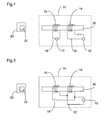
- FIGs 1 and 2 two embodiments of a device for monitoring the approach of two relatively movable parts are shown, wherein like reference numerals designate like parts.
- the relatively movable parts are in particular a door, not shown, which is pivotable in a fixed door frame.
- the device has a sensor 10, which can be arranged for example on a fixed door frame. Furthermore, the device has an actuator 20, which is arranged separately from the sensor 10, so that it is a non-contact proximity sensor in the device.
- the actuator 20 is arranged, for example, on a door pivotable in the fixed door frame, so that it is in a position close to the sensor 10 when the door is closed and moves away from the sensor 10 when the door is opened.
- a transponder 22 is arranged, which is designed in particular as a passive transponder.
- the senor 10 has a receiving circuit 12, in which a receiver coil 14 is arranged.
- a power supply 15 is arranged by means of which a current can be sent through the receiver coil 14 to generate a magnetic field in the receiver coil 14.
- the receiver coil 14 serves on the one hand as a transmitter of the magnetic field, which, if the transponder 22 is close enough to the sensor 10, represents the power supply of the transponder 22 and causes the transponder 22 falls below a predetermined proximity distance a coded in a bit pattern transponder signal transmits to the sensor 10.
- the receiving coil 14 also serves as a receiver, since it detects this transponder signal and compares it in the receiving circuit 12, in particular in an evaluation unit, not shown in the receiving circuit 12, with a stored bit pattern in order subsequently to generate an output signal for the monitoring.
- an attenuator coil 16 is arranged in the sensor 10.
- the Abschwharierspule 16 is also powered by a power supply 17 with electricity.
- the receiver coil 14 and the Abschwharierspule 16 are arranged together on a magnetic core 30, in particular a ferrite, wherein the windings of the receiver coil 14 and the Abschwharierspule 16 extend in the same direction around the magnetic core 30.
- the attenuator coil 16 In order for the attenuator coil 16 to generate a magnetic field that weakens the magnetic field of the receiver coil 14, it is necessary to flow current in the opposite direction through the receiver coil 14 and the attenuator coil 16.
- a switching element 18 is additionally arranged, with which the Abschwharierspule 16 can be switched on and off, so that a targeted, especially only temporary attenuation of the magnetic field of the receiver coil 14 can be made by the magnetic field of Abschwharierspule 16.
- a switching element 18 is additionally arranged, with which the Abschwharierspule 16 can be switched on and off, so that a targeted, especially only temporary attenuation of the magnetic field of the receiver coil 14 can be made by the magnetic field of Abschwownerspule 16.
- Another control for the Abschwharierspule 16 with which in the switched State of the Abschwharierspule 16 and the strength of the magnetic field of the Abschwharierspule 16 can be controlled.
- the exemplary embodiment of the invention illustrated in FIG. 2 differs from the exemplary embodiment illustrated in FIG. 1 in that the attenuator coil 16 and the receiver coil 14 have a common voltage supply 15 ', the receiver coil 14 and the attenuator coil 16 being connected in a common receiving circuit 12' ,
- the Abschwharierspule 16 and the receiver coil 14 are connected in parallel, wherein the Abschwharierspule 16 can in turn be switched by the switching element 18.
- the Abschw kauerspule 16 and the receiver coil 14 are in turn arranged together on the magnetic core 30, wherein their windings extend in the same direction around the magnetic core.
- the receiver coil 14 and the Abschwharierspule 16 are in particular connected in parallel so that both their on the magnetic core 30 facing each other ends and their on the magnetic core 30 opposite ends are each connected to the same pole of the power supply 15 ', so that in the same winding the receiver coil 14 and the Abschwharierspule 16 on the magnetic core 30, the two coils 14, 16 are flowed through in the opposite direction from the current, so that the magnetic field generated in the Abschwharierspule 16, the magnetic field of the receiver coil 14 weakens.
- the correct winding and interconnection of the receiver coil 14 and the Abschwharierspule 16 and thus the correct anti-phase control of the two coils 14, 16, can be checked by means of an additional test coil, not shown.
- An erroneous triggering and outputting of a signal for monitoring by the sensor 10 can be checked that the weakening coil 16, the magnetic field of the receiver coil 14 is weakened so far that the power supply of the transponder 22 is interrupted and thus the receiving circuit 12, 12 'no Signal of the transponder 22 detected more. If, nevertheless, a corresponding signal should be present for the monitoring at the output, ie that the sensor 10 despite the field weakening by the Abschwownerspule 16 does not turn off the output signal, thus the malfunction of the sensor 10 can be determined.
Landscapes
- Engineering & Computer Science (AREA)
- General Engineering & Computer Science (AREA)
- Mechanical Engineering (AREA)
- Near-Field Transmission Systems (AREA)
- Geophysics And Detection Of Objects (AREA)
- Switches That Are Operated By Magnetic Or Electric Fields (AREA)
Applications Claiming Priority (1)
| Application Number | Priority Date | Filing Date | Title |
|---|---|---|---|
| DE202006015768U DE202006015768U1 (de) | 2006-10-14 | 2006-10-14 | Vorrichtung zum Überwachen der Annäherung zweier relativ zueinander beweglicher Teile |
Publications (2)
| Publication Number | Publication Date |
|---|---|
| EP1912331A2 true EP1912331A2 (fr) | 2008-04-16 |
| EP1912331A3 EP1912331A3 (fr) | 2008-05-07 |
Family
ID=37564019
Family Applications (1)
| Application Number | Title | Priority Date | Filing Date |
|---|---|---|---|
| EP07016048A Withdrawn EP1912331A3 (fr) | 2006-10-14 | 2007-08-16 | Dispositif de surveillance du rapprochement de deux pièces se déplaçant l'une par rapport à l'autre |
Country Status (3)
| Country | Link |
|---|---|
| US (1) | US20080094240A1 (fr) |
| EP (1) | EP1912331A3 (fr) |
| DE (1) | DE202006015768U1 (fr) |
Families Citing this family (5)
| Publication number | Priority date | Publication date | Assignee | Title |
|---|---|---|---|---|
| WO2014110207A1 (fr) * | 2013-01-09 | 2014-07-17 | Frederick Energy Products, Llc | Dispositif de commande de zone mécanisée |
| US11572709B2 (en) | 2019-05-31 | 2023-02-07 | Rockwell Automation Technologies, Inc. | Guard locking switch with three concurrent directions of approach |
| US11473336B2 (en) | 2019-05-31 | 2022-10-18 | Rockwell Automation Technologies, Inc. | Sensor with three concurrent directions of approach |
| US10997486B1 (en) | 2020-02-06 | 2021-05-04 | Rockwell Automation Technologies, Inc. | RFID tag retention method within a metal plate |
| US12307880B2 (en) * | 2022-08-29 | 2025-05-20 | Comcast Cable Communications, Llc | Systems and methods for determining status of sensors |
Citations (2)
| Publication number | Priority date | Publication date | Assignee | Title |
|---|---|---|---|---|
| EP0968567A1 (fr) | 1997-03-20 | 2000-01-05 | EUCHNER GmbH + Co. | Interrupteur de securite |
| DE10334653A1 (de) | 2003-07-21 | 2005-03-03 | Pilz Gmbh & Co. Kg | Verfahren und Vorrichtung zum sicheren Überwachen einer Schließposition zweier relativ zueinander beweglicher Teile |
Family Cites Families (7)
| Publication number | Priority date | Publication date | Assignee | Title |
|---|---|---|---|---|
| DE3505765A1 (de) * | 1985-02-20 | 1986-08-21 | Werner Turck Gmbh & Co Kg, 5884 Halver | Induktiver naeherungsschalter mit pruefeinrichtung |
| JP3528367B2 (ja) * | 1995-09-30 | 2004-05-17 | ソニーケミカル株式会社 | リーダ・ライタ用アンテナ |
| DE19959233B4 (de) * | 1999-12-08 | 2007-12-13 | Tiefenbach Gmbh | Induktiver Sensor zum Erfassen von Metallteilen |
| DE10000799C1 (de) * | 2000-01-11 | 2001-05-17 | Euchner Gmbh & Co | Vorrichtung zum Schalten einer elektrischen Verbindung in Abhängigkeit des Zustandes einer zu überwachenden Einrichtung, insbesondere Sicherheitsschalter |
| DE60215382T2 (de) * | 2001-11-02 | 2007-08-23 | Avid Identification Systems, Inc., Norco | Doppelantennenspulentranspondersystem |
| US7102521B2 (en) * | 2004-04-30 | 2006-09-05 | Hewlett-Packard Development Company, L.P. | Method and system for identifying RFID-tagged objects |
| GB0505060D0 (en) * | 2005-03-11 | 2005-04-20 | Innovision Res & Tech Plc | Gain controlled impedance |
-
2006
- 2006-10-14 DE DE202006015768U patent/DE202006015768U1/de not_active Expired - Lifetime
-
2007
- 2007-08-16 EP EP07016048A patent/EP1912331A3/fr not_active Withdrawn
- 2007-10-12 US US11/974,476 patent/US20080094240A1/en not_active Abandoned
Patent Citations (2)
| Publication number | Priority date | Publication date | Assignee | Title |
|---|---|---|---|---|
| EP0968567A1 (fr) | 1997-03-20 | 2000-01-05 | EUCHNER GmbH + Co. | Interrupteur de securite |
| DE10334653A1 (de) | 2003-07-21 | 2005-03-03 | Pilz Gmbh & Co. Kg | Verfahren und Vorrichtung zum sicheren Überwachen einer Schließposition zweier relativ zueinander beweglicher Teile |
Also Published As
| Publication number | Publication date |
|---|---|
| EP1912331A3 (fr) | 2008-05-07 |
| US20080094240A1 (en) | 2008-04-24 |
| DE202006015768U1 (de) | 2006-12-14 |
Similar Documents
| Publication | Publication Date | Title |
|---|---|---|
| EP2880235B1 (fr) | Procédé de commande d'un mouvement d'un élément de fermeture d'un véhicule avec évitement de collision pour une zone de serrure et système anti-pincement | |
| EP3075613B1 (fr) | Commutateur virtuel et son procede de fonctionnement | |
| EP0968567B1 (fr) | Interrupteur de securite | |
| DE69922326T2 (de) | Elektrische Servolenkung mit Positionskalibrierung | |
| EP1912331A2 (fr) | Dispositif de surveillance du rapprochement de deux pièces se déplaçant l'une par rapport à l'autre | |
| DE102012006496A1 (de) | Fußgängerschutzeinrichtung für ein Kraftfahrzeug | |
| EP1647094B1 (fr) | Procede et dispositif de controle sur d'une position de fermeture de deux pieces pouvant se deplacer relativement l'une par rapport a l'autre | |
| EP3128220A1 (fr) | Système de sécurité | |
| DE102011087120B4 (de) | Stellantrieb einer Luftdurchlassvorrichtung | |
| AT413917B (de) | Induktiver sensor zum erfassen von metallteilen | |
| EP3580414B1 (fr) | Serrure de véhicule automobile, en particulier serrure de capot | |
| EP1702409B1 (fr) | Interrupteur de securite servant a surveiller une position de fermeture de deux pieces mobiles l'une par rapport a l'autre | |
| DE102004016632B4 (de) | Sicherheitsschalter zum Überwachen einer Schließposition zweier relativ zueinander beweglicher Teile | |
| WO2003012998A1 (fr) | Dispositif pour controler une position de fermeture de deux parties deplaçables l'une part rapport a l'autre, s'utilisant notamment comme contacteur de porte sans contact | |
| EP1473511B1 (fr) | Dispositif de protection d'accès | |
| DE10222761A1 (de) | Zahnstangenlenkung mit Stellungserfassung | |
| EP3924796B1 (fr) | Procédé et système de délimitation et de surveillance d'au moins une zone de travail pour au moins un véhicule autonome | |
| WO2017194546A1 (fr) | Ensemble de surveillance destiné à surveiller un capteur de sécurité et procédé pour surveiller un capteur de sécurité | |
| EP1301385B1 (fr) | Dispositif de controle mecanique et electrique de systeme de reglage d'appareil de commande d'aiguillage | |
| EP2683895B2 (fr) | Ensemble charnière | |
| EP0928872A1 (fr) | Système d'entrainement à moteur électrique | |
| DE102006046437B4 (de) | Vorrichtung zum Überwachen des Zustandes einer sicherheitsrelevanten Einrichtung | |
| EP1860003B1 (fr) | Dispositif de protection pour un dispositif d'allumage à bougie d'un véhicule automobile tout comme procédé correspondant | |
| DE102004002438A1 (de) | Sicherheitsschalter zum Überwachen einer Schließposition zweier relativ zueinander beweglicher Teile | |
| EP3484051B1 (fr) | Dispositif doté d'un capteur et d'un actionneur et procédé d'essai dudit dispositif |
Legal Events
| Date | Code | Title | Description |
|---|---|---|---|
| PUAI | Public reference made under article 153(3) epc to a published international application that has entered the european phase |
Free format text: ORIGINAL CODE: 0009012 |
|
| PUAL | Search report despatched |
Free format text: ORIGINAL CODE: 0009013 |
|
| AK | Designated contracting states |
Kind code of ref document: A2 Designated state(s): AT BE BG CH CY CZ DE DK EE ES FI FR GB GR HU IE IS IT LI LT LU LV MC MT NL PL PT RO SE SI SK TR |
|
| AX | Request for extension of the european patent |
Extension state: AL BA HR MK RS |
|
| AK | Designated contracting states |
Kind code of ref document: A3 Designated state(s): AT BE BG CH CY CZ DE DK EE ES FI FR GB GR HU IE IS IT LI LT LU LV MC MT NL PL PT RO SE SI SK TR |
|
| AX | Request for extension of the european patent |
Extension state: AL BA HR MK RS |
|
| RIC1 | Information provided on ipc code assigned before grant |
Ipc: F16P 3/14 20060101ALI20080401BHEP Ipc: H03K 17/95 20060101AFI20071204BHEP |
|
| STAA | Information on the status of an ep patent application or granted ep patent |
Free format text: STATUS: THE APPLICATION HAS BEEN WITHDRAWN |
|
| 18W | Application withdrawn |
Effective date: 20080614 |