EP1912371A2 - Appareil de communication sans fil - Google Patents
Appareil de communication sans fil Download PDFInfo
- Publication number
- EP1912371A2 EP1912371A2 EP07251610A EP07251610A EP1912371A2 EP 1912371 A2 EP1912371 A2 EP 1912371A2 EP 07251610 A EP07251610 A EP 07251610A EP 07251610 A EP07251610 A EP 07251610A EP 1912371 A2 EP1912371 A2 EP 1912371A2
- Authority
- EP
- European Patent Office
- Prior art keywords
- determining
- transmitted
- candidate
- vector
- vectors
- Prior art date
- Legal status (The legal status is an assumption and is not a legal conclusion. Google has not performed a legal analysis and makes no representation as to the accuracy of the status listed.)
- Withdrawn
Links
Images


Classifications
-
- H—ELECTRICITY
- H04—ELECTRIC COMMUNICATION TECHNIQUE
- H04L—TRANSMISSION OF DIGITAL INFORMATION, e.g. TELEGRAPHIC COMMUNICATION
- H04L25/00—Baseband systems
- H04L25/02—Details ; arrangements for supplying electrical power along data transmission lines
- H04L25/03—Shaping networks in transmitter or receiver, e.g. adaptive shaping networks
- H04L25/03006—Arrangements for removing intersymbol interference
- H04L25/03178—Arrangements involving sequence estimation techniques
- H04L25/03203—Trellis search techniques
- H04L25/03242—Methods involving sphere decoding
-
- H—ELECTRICITY
- H03—ELECTRONIC CIRCUITRY
- H03M—CODING; DECODING; CODE CONVERSION IN GENERAL
- H03M13/00—Coding, decoding or code conversion, for error detection or error correction; Coding theory basic assumptions; Coding bounds; Error probability evaluation methods; Channel models; Simulation or testing of codes
- H03M13/37—Decoding methods or techniques, not specific to the particular type of coding provided for in groups H03M13/03 - H03M13/35
- H03M13/45—Soft decoding, i.e. using symbol reliability information
-
- H—ELECTRICITY
- H04—ELECTRIC COMMUNICATION TECHNIQUE
- H04L—TRANSMISSION OF DIGITAL INFORMATION, e.g. TELEGRAPHIC COMMUNICATION
- H04L1/00—Arrangements for detecting or preventing errors in the information received
- H04L1/02—Arrangements for detecting or preventing errors in the information received by diversity reception
- H04L1/06—Arrangements for detecting or preventing errors in the information received by diversity reception using space diversity
- H04L1/0618—Space-time coding
- H04L1/0631—Receiver arrangements
-
- H—ELECTRICITY
- H04—ELECTRIC COMMUNICATION TECHNIQUE
- H04L—TRANSMISSION OF DIGITAL INFORMATION, e.g. TELEGRAPHIC COMMUNICATION
- H04L25/00—Baseband systems
- H04L25/02—Details ; arrangements for supplying electrical power along data transmission lines
- H04L25/03—Shaping networks in transmitter or receiver, e.g. adaptive shaping networks
- H04L25/03006—Arrangements for removing intersymbol interference
- H04L25/03178—Arrangements involving sequence estimation techniques
- H04L25/03312—Arrangements specific to the provision of output signals
- H04L25/03318—Provision of soft decisions
-
- H—ELECTRICITY
- H04—ELECTRIC COMMUNICATION TECHNIQUE
- H04L—TRANSMISSION OF DIGITAL INFORMATION, e.g. TELEGRAPHIC COMMUNICATION
- H04L25/00—Baseband systems
- H04L25/02—Details ; arrangements for supplying electrical power along data transmission lines
- H04L25/06—DC level restoring means; Bias distortion correction ; Decision circuits providing symbol by symbol detection
- H04L25/067—DC level restoring means; Bias distortion correction ; Decision circuits providing symbol by symbol detection providing soft decisions, i.e. decisions together with an estimate of reliability
-
- H—ELECTRICITY
- H04—ELECTRIC COMMUNICATION TECHNIQUE
- H04L—TRANSMISSION OF DIGITAL INFORMATION, e.g. TELEGRAPHIC COMMUNICATION
- H04L25/00—Baseband systems
- H04L25/02—Details ; arrangements for supplying electrical power along data transmission lines
- H04L25/03—Shaping networks in transmitter or receiver, e.g. adaptive shaping networks
- H04L25/03006—Arrangements for removing intersymbol interference
- H04L2025/0335—Arrangements for removing intersymbol interference characterised by the type of transmission
- H04L2025/03426—Arrangements for removing intersymbol interference characterised by the type of transmission transmission using multiple-input and multiple-output channels
-
- H—ELECTRICITY
- H04—ELECTRIC COMMUNICATION TECHNIQUE
- H04L—TRANSMISSION OF DIGITAL INFORMATION, e.g. TELEGRAPHIC COMMUNICATION
- H04L25/00—Baseband systems
- H04L25/02—Details ; arrangements for supplying electrical power along data transmission lines
- H04L25/0202—Channel estimation
- H04L25/0204—Channel estimation of multiple channels
Definitions
- the present invention is in the field of wireless communication, and particularly, but not exclusively, the field of multiple input, multiple output (MIMO) communications systems.
- MIMO multiple input, multiple output
- y Hx + v in which, for a MIMO communication system, y is an n -by-1 vector representing the received signal, H is an n-by-m channel matrix modelling the transmission characteristics of the communications channel, x is an m -by-1 vector representing transmit symbols, v is an n -by-1 noise vector and wherein m and n denote the number of transmit and receive antennas respectively.
- Lattice-Reduction-Aided Detectors for MIMO Communication Systems (H. Yao and G.W. Womell, Proc. IEEE Globecom, Nov 2002, pp. 424-428 ) describes Lattice-reduction (LR) techniques for enhancing the performance of multiple-input multiple-output (MIMO) digital communication systems.
- LR Lattice-reduction
- Berenguer et al. Lattice-Reduction-Aided Receivers for MIMO-OFDM in Spatial Multiplexing Systems
- Berenguer et al. describes the use of Orthogonal Frequency Division Multiplexing (OFDM) to significantly reduce receiver complexity in wireless systems with Multipath propagation, and notes its proposed use in wireless broadband multi-antenna (MIMO) systems.
- OFDM Orthogonal Frequency Division Multiplexing
- Berenguer et al. describes the equivalent method in the complex plane, though for the purpose of clarity the Real axis representation of the method is used herein.
- LLLL Lenstra-Lenstra-Lovasz
- the matrix T contains only integer entries and its determinant is +/-1.
- H ⁇ r Since H ⁇ r is close to orthogonal, z ⁇ r should suffer much less noise enhancement than if the receiver directly equalised the channel H r .
- MMSE techniques or more complex successive interference cancellation based methods, such as in the published prior art identified above, could be considered for use.
- a receiver in accordance with the above operates in the knowledge that the transmitted symbols contained in x are obtained from an M-QAM constellation.
- Figure 1 demonstrates the relative performance of techniques in accordance with the published art, including the above described example thereof, over other MIMO detection methods for an uncoded system.
- 'ZF' and 'MMSE' refer to the standard linear detection methods
- 'RL-ZF' and 'RL-MMSE' refer to the lattice reduction aided methods
- 'Sphere' refers to results obtained using the Sphere decoding algorithm (almost identical to the performance of maximum-likelihood detection).
- Such reduced lattice detectors usually output hard decisions.
- the only mention in the literature of a technique that could be employed for obtaining soft-output is " From Lattice-Reduction-Aided Detection Towards Maximum-Likelihood Detection in MIMO Systems", (C. Windpassinger, L. Lampe and R. Fischer, in Proc. Int. Conf. on Wireless and Optical Communications, Banff, Canada, July 2003, hereinafter referred to as "Windpassinger et al.”).
- the method that Windpassinger et al. proposes is complex, and the performance of this technique was not validated in the publication. Therefore it is an aim of aspects of the present invention to provide a MIMO detector capable of determining a soft output using a simple and proven approach.
- US Patent 6724843 describes a detector in which received symbols are decoded in a multiple-antenna communication system using lattice-based decoding.
- the symbols are generated using a modulation constellation, e.g., a diagonal modulation constellation, and the constellation is characterized as a lattice for decoding purposes.
- a modulation constellation e.g., a diagonal modulation constellation
- the constellation is characterized as a lattice for decoding purposes.
- the diagonal modulation constellation can be characterized as a lattice in M dimensions.
- a differential decoding operation for received differential symbols involves a determination of the closest point in the lattice corresponding to the constellation.
- This determination may be made in an efficient manner using a basis reduction algorithm which generates an approximately orthogonal basis for the lattice, and then utilizes component-wise rounding to determine the closest point.
- the lattice-based decoding has a complexity which is polynomial rather than exponential in the particular number of antennas and the system rate, but is nonetheless able to deliver error rate performance which approximates that of maximum likelihood decoding.
- the reduced lattice detection schemes described in all other references only output hard decisions for the estimate of the transmitted symbol vector, x ⁇ .
- the performance of the code can be substantially improved if it is supplied with soft-information, e.g. a log-likelihood ratio (LLR) for each bit.
- LLR log-likelihood ratio
- the method in accordance with the invention is suitable for use in a MIMO wireless communications system. Further, it can be used with any other system wherein a received signal is the result of transmission from a plurality of antennas, which may or may not be collocated. Further, the method is applicable to CDMA systems, such as multi-user detection (MUD).
- the probabilities determined in either the method according to the invention or by the detector according to the invention can be converted into LLRs.
- aspects of the invention can be delivered in the form of processor executable instructions for configuring a general purpose, communications compatible computer.
- Such instructions may be provided in software form, such as a carrier, a storage medium or a signal.
- the instructions may be provided on a solid state memory means, such as flash memory, or by means of an ASIC or other preconfigured processing means.
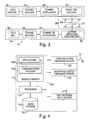
- FIG. 3 illustrates such a system, comprising a MIMO data communications system 10 of generally known construction.
- the communications system 10 comprises a transmitter device 12 and a receiver device 14. It will be appreciated that in many circumstances, a wireless communications device will be provided with the facilities of a transmitter and a receiver in combination but, for this example, the devices have been illustrated as one way communications devices for reasons of simplicity.
- the transmitter device 12 comprises a data source 16, which provides data (comprising information bits or symbols) to a channel encoder 18.
- the channel encoder 18 is followed by a channel interleaver 20 and, in the illustrated example, a space-time encoder 22.
- the space-time encoder 22 encodes an incoming symbol or symbols as a plurality of code symbols for simultaneous transmission from a transmitter antenna array 24 comprising a plurality of transmit antennas 25. In this illustrated example, three transmit antennas 25 are provided, though practical implementations may include more, or fewer antennas depending on the application.
- the encoded transmitted signals propagate through a MIMO channel 28 defined between the transmit antenna array 24 and a corresponding receive antenna array 26 of the receiver device 14.
- the receive antenna array 26 comprises a plurality of receive antennas 27 which provide a plurality of inputs to a lattice-reduction-aided decoder 30 of the receiver device 14.
- the receive antenna array 26 comprises three receive antennas 27.
- the lattice-reduction-aided decoder 30 has the task of removing the effect of the MIMO channel 28.
- the output of the lattice-reduction-aided decoder 30 comprises a plurality of signal streams, one for each transmit antenna 25, each carrying so-called soft or likelihood data on the probability of a transmitted bit having a particular value.
- This data is provided to a channel de-interleaver 32 which reverses the effect of the channel interleaver 20, and the de-interleaved bits output by this channel de-interleaver 32 are then presented to a channel decoder 34, in this example a Viterbi decoder, which decodes the convolutional code.
- the output of channel decoder 34 is provided to a data sink 36, for further processing of the data in any desired manner.
- FIG. 4 illustrates schematically hardware operably configured (by means of software or application specific hardware components) as the receiver device 16.
- the receiver device 16 comprises a processor 110 operable to execute machine code instructions stored in a working memory 112 and/or retrievable from a mass storage device 116.
- user operable input devices 118 are capable of communication with the processor 110.
- the user operable input devices 118 comprise, in this example, a keyboard and a mouse though it will be appreciated that any other input devices could also or alternatively be provided, such as another type of pointing device, a writing tablet, speech recognition means, or any other means by which a user input action can be interpreted and converted into data signals.
- Audio/video output hardware devices 120 are further connected to the general purpose bus 114, for the output of information to a user.
- Audio/video output hardware devices 120 can include a visual display unit, a speaker or any other device capable of presenting information to a user.
- Communications hardware devices 122 connected to the general purpose bus 114, are connected to the antenna 26.
- the working memory 112 stores user applications 130 which, when executed by the processor 110, cause the establishment of a user interface to enable communication of data to and from a user.
- the applications in this embodiment establish general purpose or specific computer implemented utilities that might habitually be used by a user.
- Communications facilities 132 in accordance with the specific embodiment are also stored in the working memory 112, for establishing a communications protocol to enable data generated in the execution of one of the applications 130 to be processed and then passed to the communications hardware devices 122 for transmission and communication with another communications device.
- the software defining the applications 130 and the communications facilities 132 may be partly stored in the working memory 112 and the mass storage device 116, for convenience.
- a memory manager could optionally be provided to enable this to be managed effectively, to take account of the possible different speeds of access to data stored in the working memory 112 and the mass storage device 116.
- the processor 110 On execution by the processor 110 of processor executable instructions corresponding with the communications facilities 132, the processor 110 is operable to establish communication with another device in accordance with a recognised communications protocol.
- step S1-2 the vector ⁇ r is taken as the first entry in a list of candidate vectors.
- Other candidate vectors are then obtained in step S1-4 by modifying one or more elements of the vector ⁇ r and adding these as new candidate vectors to the list.
- any of these additional candidate vectors may differ from ⁇ r in more than one element
- the present embodiment generates candidates by only ever allowing these to vary one element of ⁇ r , for reasons of simplicity, both of the present description and of computation.
- c (1) and c ( i , i ⁇ 1) are additionally referred to as the 'initial' and 'further' candidate vectors, respectively.
- a particular method of generating a list of candidates is to perturb each element of ⁇ r in turn by +/- ⁇ (where ⁇ is the minimum distance between 2 constellation points, as defined above with reference to figure 2).
- ⁇ r is a 2-by-1 vector
- there would be 4 further candidate vectors, giving a total of 5 candidates as follows: c 1 z ⁇ r ⁇ 1 z ⁇ r ⁇ 2
- c 2 z ⁇ r ⁇ 1 + ⁇ z ⁇ r ⁇ 2
- c 3 z ⁇ r ⁇ 1 + ⁇ z ⁇ r ⁇ 2
- c 4 z ⁇ r ⁇ 1 z ⁇ r ⁇ 2 + ⁇
- c 5 z ⁇ r ⁇ 1 z ⁇ r ⁇ 2 - ⁇ .
- the effect of perturbing elements of ⁇ r is to generate other points in the reduced lattice.
- the perturbations by +/- ⁇ give the closest points in the lattice as the distance between any two neighbouring points.
- An implementation may alternatively choose to increase the list of candidates through perturbing elements of ⁇ r by multiples of ⁇ (i.e. to not just the closest point, but the closest few points).
- each candidate is converted to a transmitted symbol vector estimate.
- the vectors x ⁇ r 1 and x ⁇ r i , i ⁇ 1 are additionally referred to as the 'initial' and 'further' transmitted symbol vectors and correspond to c (1) and c ( i , i ⁇ 1) , respectively.
- step S1-8 seeks to determine if this is the case, and, if so, in step S1-10, these symbols are mapped to the nearest valid symbol. For example, for 16-QAM, if the values +/-1, +/-3 define the valid entries as illustrated in figure 2, then if an element were, for example, equal to +5, this would be mapped to a value of+3.
- step S1-14 the probability of symbol x' having been transmitted from antenna k, where x' ⁇ X and X defines the set of symbols in the chosen constellation.
- P k , x ⁇ ⁇ ⁇ i
- P may not be specified for all values of k and x '.
- P is set to a default (small) value.
- This default can be a fixed value or it could varied according to a method such as that described in " Adaptive Selection of Surviving Symbol Replica Candidates Based on Maximum Reliability in QRM-MLD for OFCDM MIMO Multiplexing" (K. Higuchi, H. Kawai, N. Maeda and M. Sawahashi, in Proc. IEEE Globecom, Dallas, Dec. 2004 ), or by any other appropriate method.
- LLR log-likelihood ratio
- ⁇ y r - H r ⁇ x ⁇ r i ⁇ 2 represents the Euclidean distance, d ( i ) , in M-QAM constellation space, of transmitted symbol vector x ⁇ r i .
- step S1-16 A detailed description of the step performed at step S1-16 will now be described with reference to figure 6.
- a modified channel state matrix, ( ⁇ HT ), and associated values, such as its column norms, are calculated in step S2-4. However, it is noted that these may be pre-computed for a given channel state, H, and stored in working memory 112 of the receiver in order to expedite the subsequent step and reduce its computational complexity.
- the graph of figure 7 sets out experimental performance data of a method performed in accordance with the present embodiment in comparison with prior art decoding methods aiming to provide hard information for the channel decoder.
- Figure 7 demonstrates the benefit that can be obtained by providing a lattice reduction detection scheme to output soft information for the channel decoder.
- the invention has been described by way of a software implementation.
- This software implementation can be introduced as a stand alone software product, such as borne on a storage medium, e.g. an optical disk, or by means of a signal. Further, the implementation could be by means of an upgrade or plug-in to existing software.
- the invention can be so provided, it could also be by way exclusively by hardware, such as on an ASIC, a DSP board, a solid state memory means, such as flash memory, or the like.
Landscapes
- Engineering & Computer Science (AREA)
- Computer Networks & Wireless Communication (AREA)
- Signal Processing (AREA)
- Power Engineering (AREA)
- Physics & Mathematics (AREA)
- Probability & Statistics with Applications (AREA)
- Theoretical Computer Science (AREA)
- Radio Transmission System (AREA)
- Error Detection And Correction (AREA)
Applications Claiming Priority (1)
| Application Number | Priority Date | Filing Date | Title |
|---|---|---|---|
| GB0620072A GB2442785B (en) | 2006-10-10 | 2006-10-10 | Wireless communications apparatus |
Publications (2)
| Publication Number | Publication Date |
|---|---|
| EP1912371A2 true EP1912371A2 (fr) | 2008-04-16 |
| EP1912371A3 EP1912371A3 (fr) | 2008-06-25 |
Family
ID=37491246
Family Applications (1)
| Application Number | Title | Priority Date | Filing Date |
|---|---|---|---|
| EP07251610A Withdrawn EP1912371A3 (fr) | 2006-10-10 | 2007-04-17 | Appareil de communication sans fil |
Country Status (6)
| Country | Link |
|---|---|
| US (1) | US20080123764A1 (fr) |
| EP (1) | EP1912371A3 (fr) |
| JP (1) | JP2010506436A (fr) |
| CN (1) | CN101341705A (fr) |
| GB (1) | GB2442785B (fr) |
| WO (1) | WO2008047737A2 (fr) |
Cited By (1)
| Publication number | Priority date | Publication date | Assignee | Title |
|---|---|---|---|---|
| KR101497975B1 (ko) * | 2008-05-13 | 2015-03-03 | 삼성전자주식회사 | 다중 입출력 통신 시스템을 위한 교란 벡터를 이용한 디코더 및 디코딩 방법 |
Families Citing this family (10)
| Publication number | Priority date | Publication date | Assignee | Title |
|---|---|---|---|---|
| EP2200240B1 (fr) * | 2008-12-18 | 2011-06-15 | STMicroelectronics Srl | Procédé et appareil pour le calcul quasi optimal d'information de fiabilité des bits dans des systèmes de communication à antennes multiples avec détection et décodage itératifs |
| IL204565A0 (en) | 2010-03-17 | 2010-11-30 | Nds Ltd | Data expansion using an approximate method |
| US9130629B2 (en) * | 2011-03-04 | 2015-09-08 | Sharp Kabushiki Kaisha | Wireless communication system, base station device, and terminal device |
| US9838226B2 (en) | 2012-01-27 | 2017-12-05 | Apple Inc. | Methods and apparatus for the intelligent scrambling of control symbols |
| US8897398B2 (en) * | 2012-01-27 | 2014-11-25 | Apple Inc. | Methods and apparatus for error rate estimation |
| US9450790B2 (en) | 2013-01-31 | 2016-09-20 | Apple Inc. | Methods and apparatus for enabling and disabling scrambling of control symbols |
| US9210010B2 (en) | 2013-03-15 | 2015-12-08 | Apple, Inc. | Methods and apparatus for scrambling symbols over multi-lane serial interfaces |
| WO2019051093A1 (fr) * | 2017-09-06 | 2019-03-14 | Cohere Technologies | Réduction de treillis en modulation temporelle, fréquentielle et spatiale orthogonale |
| JP2019054448A (ja) * | 2017-09-15 | 2019-04-04 | 東芝メモリ株式会社 | メモリシステム |
| US11309992B2 (en) * | 2018-07-17 | 2022-04-19 | Qualcomm Incorporated | Using lattice reduction for reduced decoder complexity |
Family Cites Families (4)
| Publication number | Priority date | Publication date | Assignee | Title |
|---|---|---|---|---|
| US7236536B2 (en) * | 2001-07-26 | 2007-06-26 | Lucent Technologies Inc. | Method and apparatus for detection and decoding of signals received from a linear propagation channel |
| US7349496B2 (en) * | 2003-06-27 | 2008-03-25 | Nortel Networks Limited | Fast space-time decoding using soft demapping with table look-up |
| GB2411328B (en) * | 2004-02-23 | 2007-05-16 | Toshiba Res Europ Ltd | Adaptive MIMO systems |
| GB2426419B (en) * | 2005-05-18 | 2007-04-04 | Toshiba Res Europ Ltd | Signal processing systems |
-
2006
- 2006-10-10 GB GB0620072A patent/GB2442785B/en not_active Expired - Fee Related
-
2007
- 2007-04-17 EP EP07251610A patent/EP1912371A3/fr not_active Withdrawn
- 2007-05-18 US US11/750,366 patent/US20080123764A1/en not_active Abandoned
- 2007-10-09 CN CNA2007800007899A patent/CN101341705A/zh active Pending
- 2007-10-09 JP JP2009516435A patent/JP2010506436A/ja not_active Abandoned
- 2007-10-09 WO PCT/JP2007/070037 patent/WO2008047737A2/fr not_active Ceased
Cited By (1)
| Publication number | Priority date | Publication date | Assignee | Title |
|---|---|---|---|---|
| KR101497975B1 (ko) * | 2008-05-13 | 2015-03-03 | 삼성전자주식회사 | 다중 입출력 통신 시스템을 위한 교란 벡터를 이용한 디코더 및 디코딩 방법 |
Also Published As
| Publication number | Publication date |
|---|---|
| GB2442785B (en) | 2008-12-24 |
| JP2010506436A (ja) | 2010-02-25 |
| GB0620072D0 (en) | 2006-11-22 |
| GB2442785A (en) | 2008-04-16 |
| US20080123764A1 (en) | 2008-05-29 |
| EP1912371A3 (fr) | 2008-06-25 |
| WO2008047737A3 (fr) | 2008-07-24 |
| CN101341705A (zh) | 2009-01-07 |
| WO2008047737A2 (fr) | 2008-04-24 |
Similar Documents
| Publication | Publication Date | Title |
|---|---|---|
| EP1912371A2 (fr) | Appareil de communication sans fil | |
| EP1895730A1 (fr) | Génération de décisions douces dans un système MIMO à réduction de réseau | |
| US20070121753A1 (en) | Wireless communications apparatus | |
| KR101124863B1 (ko) | 다중 소스로부터의 통신신호를 처리하는 장치 및 방법 | |
| US7583763B2 (en) | Multi input multi output wireless communication reception method and apparatus | |
| US11190259B2 (en) | Detection method for lattice reduction-aided MIMO system receiver and iterative noise cancellation | |
| EP1879341A2 (fr) | Detection de donnée avec la reduction de lattice en utilisant un algorithme modifié de Lenstra-Lenstra-Lovasz (LLL) | |
| EP1912396A2 (fr) | Appareil de communication sans fil | |
| Silvola et al. | Suboptimal soft-output MAP detector with lattice reduction | |
| EP2680520B1 (fr) | Procédé et dispositif de réception efficace et à complexité réduite de signaux dans un système de communication de type MIMO | |
| Chen et al. | Markov chain Monte Carlo: Applications to MIMO detection and channel equalization | |
| Ali et al. | Sequential decoders for large MIMO systems | |
| EP2858285A1 (fr) | Procédé de détection de symboles dans des signaux de communication | |
| GB2426419A (en) | A hardware accelerator for a signal decoder | |
| Chtourou et al. | Efficient doubly-iterative frequency domain turbo-equalization for single-carrier transmission over MIMO ISI channel | |
| GB2446659A (en) | Controlling LLL Lattice reduction runtimes in wireless MIMO receivers | |
| Li et al. | Iterative successive interference cancellation based on multiple feedback for multiuser MIMO systems | |
| WO2015046026A1 (fr) | Procédé et dispositif pour décoder des symboles reçus correspondant à des symboles de constellation pam tels que transmis via un canal mimo | |
| Wang et al. | Three-Stage Serially Concatenated Codes and Iterative Center-Shifting K-Best Sphere Detection for SDM-OFDM: An EXIT Chart Aided Perspective | |
| GB2457507A (en) | Lattice reduction for detection of MIMO systems using an LLL-based algorithm | |
| Dang | Trellis Based Receivers for SC FDMA Transmission Over MIMO ISI Channels |
Legal Events
| Date | Code | Title | Description |
|---|---|---|---|
| PUAI | Public reference made under article 153(3) epc to a published international application that has entered the european phase |
Free format text: ORIGINAL CODE: 0009012 |
|
| 17P | Request for examination filed |
Effective date: 20070423 |
|
| AK | Designated contracting states |
Kind code of ref document: A2 Designated state(s): AT BE BG CH CY CZ DE DK EE ES FI FR GB GR HU IE IS IT LI LT LU LV MC MT NL PL PT RO SE SI SK TR |
|
| AX | Request for extension of the european patent |
Extension state: AL BA HR MK RS |
|
| PUAL | Search report despatched |
Free format text: ORIGINAL CODE: 0009013 |
|
| AK | Designated contracting states |
Kind code of ref document: A3 Designated state(s): AT BE BG CH CY CZ DE DK EE ES FI FR GB GR HU IE IS IT LI LT LU LV MC MT NL PL PT RO SE SI SK TR |
|
| AX | Request for extension of the european patent |
Extension state: AL BA HR MK RS |
|
| RIC1 | Information provided on ipc code assigned before grant |
Ipc: H04B 7/04 20060101ALI20080520BHEP Ipc: H04L 1/06 20060101ALI20080520BHEP Ipc: H04L 25/06 20060101ALI20080520BHEP Ipc: H04L 25/03 20060101AFI20080520BHEP |
|
| AKX | Designation fees paid |
Designated state(s): DE FR |
|
| STAA | Information on the status of an ep patent application or granted ep patent |
Free format text: STATUS: THE APPLICATION IS DEEMED TO BE WITHDRAWN |
|
| 18D | Application deemed to be withdrawn |
Effective date: 20111101 |