EP1912463A2 - Système de communication mobile et procédé de contrôle de transfert - Google Patents
Système de communication mobile et procédé de contrôle de transfert Download PDFInfo
- Publication number
- EP1912463A2 EP1912463A2 EP20070253587 EP07253587A EP1912463A2 EP 1912463 A2 EP1912463 A2 EP 1912463A2 EP 20070253587 EP20070253587 EP 20070253587 EP 07253587 A EP07253587 A EP 07253587A EP 1912463 A2 EP1912463 A2 EP 1912463A2
- Authority
- EP
- European Patent Office
- Prior art keywords
- cell
- base station
- mobile station
- power
- received signal
- Prior art date
- Legal status (The legal status is an assumption and is not a legal conclusion. Google has not performed a legal analysis and makes no representation as to the accuracy of the status listed.)
- Granted
Links
- 238000010295 mobile communication Methods 0.000 title claims description 44
- 238000000034 method Methods 0.000 title claims description 15
- 230000005540 biological transmission Effects 0.000 claims abstract description 58
- 238000006243 chemical reaction Methods 0.000 claims description 12
- 230000003247 decreasing effect Effects 0.000 claims description 3
- 230000004044 response Effects 0.000 claims description 3
- 230000001419 dependent effect Effects 0.000 claims description 2
- 238000004891 communication Methods 0.000 description 33
- 238000005259 measurement Methods 0.000 description 29
- 230000015556 catabolic process Effects 0.000 description 10
- 238000006731 degradation reaction Methods 0.000 description 10
- 238000010586 diagram Methods 0.000 description 9
- 238000012937 correction Methods 0.000 description 6
- 238000012217 deletion Methods 0.000 description 5
- 230000037430 deletion Effects 0.000 description 5
- 230000008569 process Effects 0.000 description 5
- 230000003321 amplification Effects 0.000 description 3
- 238000003199 nucleic acid amplification method Methods 0.000 description 3
- 230000008901 benefit Effects 0.000 description 2
- 230000007423 decrease Effects 0.000 description 2
- 230000006870 function Effects 0.000 description 2
- 230000008859 change Effects 0.000 description 1
- 239000000284 extract Substances 0.000 description 1
- 230000007480 spreading Effects 0.000 description 1
- 230000007704 transition Effects 0.000 description 1
Images


Classifications
-
- H—ELECTRICITY
- H04—ELECTRIC COMMUNICATION TECHNIQUE
- H04W—WIRELESS COMMUNICATION NETWORKS
- H04W36/00—Hand-off or reselection arrangements
- H04W36/16—Performing reselection for specific purposes
- H04W36/18—Performing reselection for specific purposes for allowing seamless reselection, e.g. soft reselection
-
- H—ELECTRICITY
- H04—ELECTRIC COMMUNICATION TECHNIQUE
- H04W—WIRELESS COMMUNICATION NETWORKS
- H04W36/00—Hand-off or reselection arrangements
- H04W36/24—Reselection being triggered by specific parameters
- H04W36/30—Reselection being triggered by specific parameters by measured or perceived connection quality data
- H04W36/304—Reselection being triggered by specific parameters by measured or perceived connection quality data due to measured or perceived resources with higher communication quality
-
- H—ELECTRICITY
- H04—ELECTRIC COMMUNICATION TECHNIQUE
- H04W—WIRELESS COMMUNICATION NETWORKS
- H04W36/00—Hand-off or reselection arrangements
- H04W36/34—Reselection control
- H04W36/38—Reselection control by fixed network equipment
-
- H—ELECTRICITY
- H04—ELECTRIC COMMUNICATION TECHNIQUE
- H04W—WIRELESS COMMUNICATION NETWORKS
- H04W92/00—Interfaces specially adapted for wireless communication networks
- H04W92/04—Interfaces between hierarchically different network devices
- H04W92/12—Interfaces between hierarchically different network devices between access points and access point controllers
Definitions
- the present invention relates to a mobile communication system and, in particular, to handover control in a mobile communication system.
- CDMA Code Division Multiple Access
- a mobile station receives signals having a certain frequency and extracts a desired signal from among the received signals by performing despreading using one spread code.
- the mobile station can receive signals from multiple cells at a time by using multiple spread codes.
- the mobile station switches between cells from which the mobile station is to receive a signal while receiving signals from multiple cells at one time, thus implementing seamless handover.
- a radio base station sends different CPICH (common pilot channel) signals for different cells.
- a mobile station receives a CPICH signal, identifies the cell that sent the CPICH signal, and compares the power of the received CPICH signal with a threshold. The comparison is made in order to determine the line conditions of the path of the CPICH signal. Based on the result of the comparison of each received CPICH signal with the threshold, the mobile station determines a cell from which the mobile station should receive a signal.
- the cell from which a mobile station receives a signal will be referred to as handover target cell.
- the mobile station determines a cell from which the mobile station will receive a signal, namely a handover target cell, the mobile station adds and/or deletes a cell on the basis of the determination. Any value of the threshold within the limits of signal power at which signals can be received can be set.
- the transmission power of CPICH signals from radio base stations are not equal among all cells.
- the transmission power of CPICH signals differs among DCis, a mobiie station cannot properiy determine the line conditions of paths on the basis of the power of CPICH signals that the mobile station received.
- an uplink dedicated channel signal directed from a mobile station to cells is transmitted at a common level, and the transmission power does not differ in the cells.
- the received power of the uplink dedicated channel signal varies depending on losses on paths. Because a mobile station makes determination regarding handover on the basis of the received power of CPICH signals, it is possible that a path with a large loss is selected as a handover target. If this occurs, the power of the signal of the uplink dedicated channel received at the radio base station is weakened.
- a radio base station can combine signals received in multiple cells.
- the radio base station can receive a dedicated channel signal having relatively good quality.
- the radio base station cannot receive a dedicated channel signal that has a good quality.
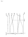
- FIG. 1 is a diagram illustrating the relationship between the power of a received CPICH signal and path loss. It is assumed here that CPICH signals from first and second cells reached a mobile station.
- PT1 in FIG. 1 represents the transmission power of the CPICH signal of the first cell and PT2 represents the transmission power of the CPICH signal of the second cell.
- PR1 represents the power of the CPICH signal from the first cell received at the mobile station and PR2 represents the power of the CPICH signal from the second cell received at the mobile station.
- L1 represents path ioss between the first cell and the mobile station and L2 represents path loss between the second cell and the mobile station.
- the loss in the uplink dedicated channel signal over the path between the mobile station and the second cell is greater than the loss in the uplink dedicated channel signal over the path between the mobile station and the first cell, the power of the signal received through the path between the mobile station and the second cell is higher.
- the downlink dedicated channel signals from the cells to the mobile station are amplified to different degrees by transmission power control.
- transmission power at a radio base station is controlled to a high level or the power of a signal of a downlink dedicated channel received at a mobile station can be decreased.
- CDMA mobile communication system that, unlike the system described above, allows a mobile station to use a downlink dedicated channel signal, in addition to a common channel signal, to determine a handover target cell (see Japanese Patent Laid-Open No. 2006-54625 ).
- An object of at least the preferred embodiments of the present invention is to provide a mobile communication system capable of reducing degradation of communication quality caused by the difference between cells in transmission power of a common channel signal.
- An object of at least the preferred embodiments of the present invention is to provide a mobile communication system capable of reducing degradation of communication quality caused by the difference in transmission power of a common channel signal between cells.
- a mobile communication system that enables handover using multiple cells, comprising: a base station which forms a cell for connecting to a mobile station by radio and, when receiving from the mobile station a report of the received signal power of a common pilot channel of each of cells received by the mobile station, converts the received signal power in the report on the basis of the transmission power of the common pilot channel of each of the cells and transfers the report containing the converted received signal power; and a base station controller which receives the report transferred from the base station and determines a cell to which the mobile station is to be connected, on the basis of the received signal power of the common pilot channel of each of the cells that is contained in the report.
- a mobile communication system that enables handover using a plurality of cells, comprising: a base station which forms a cell for connecting to a mobile station by radio and, when receiving from the mobile station a report of received signal power of a common pilot channel of each of cells received at the mobile station, transfers the report; and, a base station controller which receives the report transferred by the base station, converts the received signal power in the report on the basis of transmission power of the common pilot channel in each of the cells, and determines a cell to which the mobile station is to be connected, on the basis of the converted received signal power of the common pilot channel of each of the cells.
- a handover control method in a mobile communication system that enables handover using a plurality of cells, comprising: receiving from a mobile station a report of received signal power of a common pilot channel of each of the cells received at the mobile station, converting the received signal power in the report on the basis of the transmission power of the common pilot channel of each cell; and, determining a cell to which the mobile station is to be connected, on the basis of the converted received signal power of the common pilot channel of each of the cells.
- the invention provides in a fourth aspect a mobile communication system comprising means for implementing the method as set forth above.
- FIGS. 2 and 3 are block diagrams showing configurations of a mobile communication system according to a first exemplary embodiment of the present invention.
- mobile station 101 is in a soft handover state.
- mobile station 101 is in a softer handover state.
- the soft handover state is a state in which handover is being made across multiple radio base stations.
- the softer handover state is a state in which handover is made across multiple cells of one radio base station.
- the mobile communication system includes base stations 102 and 103, base station controller 106, and switching center 107. Multiple base stations are connected to base station controller 106 and two of them, 102 and 103, are shown. The base station controller and base stations form a radio access network.
- Mobile station 101 is a radio communication terminal, such as a mobile phone, that is capable of having multiple cells as handover targets and sending and receiving signals to and from the multiple handover target cells at the same time.
- Mobile station 101 in FIG. 2 sits in an overlapping region of two cells 104 and 105, has two cells 104 and 105 as handover target cells, and receives downlink signals from cells 104 and 105.
- An uplink signal transmitted from mobile station 101 is received by cells 104 and 105.
- Base stations 102 and 103 which are connected to base station controller 106, are radio base stations that connect to mobile station 101 with a radio signal to enable communication between mobile station 101 and base station controller 106.
- Base station 102 in FIG. 2 forms cell 104 and base station 103 forms cell 105.
- Base station controller 106 is connected with base stations 102 and 103 and switching center 107 and controls base stations 102 and 103 to enable mobile station 101 to perform communication. For example, base station controller 106 calls mobile station 101 through base station 102, 103 during establishment of a call and establishes and deletes a path in handover control during communication.
- Switching center 107 is a device that is connected with base station controller 106 and another network and switches lines for communications performed by mobile station 101 through base station controller 106.
- mobile station 101 is in the soft handover state as described above and is connected to both base stations 102 and 103.
- Communication data of mobile station 101 is transmitted over both of path of cell 104 through base station 102 and path of cell 105 through base station 103.
- the communication data may be voice data, or non-voice data, or its control signal.
- Mobile station 101 establishes a connection with base station controller 106 through base stations 102 and 103 and transmits and receives control information to and from base station controller 106 over the connection.
- Communication data transmitted from mobile station 101 is transferred to another network through base stations 102 and 103, base station controller 106, and switching center 107, and eventually to a correspondent node (not shown).
- communication data transmitted from the correspondent node is transferred to mobile station 101 through the reverse path.
- base station 201 is connected to a base station controller 106.
- Base station 201 has functions similar to those of base stations 102 and 103 shown in FIG. 2. Unlike base stations 102 and 103.
- base station 201 forms two cells 202 and 203 having the same frequency.
- a mobile station 101 in FIG. 3 sits in an overlapping region of cells 202 and 203.
- mobile station 101 is in a softer handover state and is connected to both cells 202 and 203.
- Communication data of mobile station 101 is transmitted through both of paths of cells 202 and 203.
- Mobile station 101 establishes a connection with base station controller 106 through base station 201 and transmits and receives control information to and from base station controller 106 over the connection.
- Communication data transmitted from mobile station 101 is transferred to another network through base station 201, base station controller 106, and switching center 107, and eventually to a correspondent node (not shown).
- communication data transmitted from the correspondent node is transferred to mobile station 101 through the reverse path.
- Mobile station 101 in the state shown in FIG. 2 or 3 receives a CPICH signal of each cell from each base station and measures the received power of the CPICH signal of the cell received. Mobile station 101 provides measurement information including the result of the measured received signal power to base station controller 106 through the base station.
- Base stations 102, 103, 201 convert the received signal power included in the measurement information transmitted from mobile station 101 before transferring the measured information to base station controller 106, rather than directly transferring the information.
- the base station has stored the transmission power value of the CPICH signal of each cell beforehand.
- the base station corrects the received power of the CPICH signal included in the measurement information received from mobile station 101 on the basis of the transmission power value of that CPICH signal. This correction converts the received power of the CPICH signal to a value that reflects an estimated loss on the path.
- Base station controller 106 determines a handover target cell on the basis of the received signal power of each cell measured at mobile station 101 and corrected at the base station and instructs the base station to establish or release the path of the CPICH signal of each cell when controlling handover.
- FIG. 4 is a block diagram showing a configuration of a base station according to the first exemplary embodiment.
- the configuration of base station 301 shown in FIG. 4 is common among base stations 102 and 103 shown in FIG. 2 and base station 201 shown in FIG. 3.
- base station 301 includes a transmitting and receiving antenna 302, transmitter 303, receiver 304, controller 305, and interface 306. Transmitting and receiving antenna 302, transmitter 303, and receiver 304 are provided for each cell. Accordingly, base station 201 that forms multiple cells includes multiple transmitting and receiving antennas 302, transmitters 303, and receivers 304.
- Transmitting and receiving antenna 302 is designed for transmitting and receiving radio signals and is used in communication with mobile stations 101.
- Transmitter 303 amplifies communication data, which is an RF signal, from controller 305 to be transmitted and transmits the amplified communication data to mobile station 101 through transmitting and receiving antenna 302.
- the degree of amplification of communication data by transmitter 303 is variable and is set in accordance with an instruction from controller 305.
- the instruction from controller 305 is based on TPC (Transmit Power Control) information provided by mobile station 101. Since communication data is transmitted through a dedicated channel, the CPICH signal of a common channel is amplified separately from the communication data. The CPICH signal is transmitted at a transmission power that is fixed for each cell.
- Receiver 304 amplifies an RF signal received from mobile station 101 through transmitting and receiving antenna 302 and sends the amplified RF signal to controller 305. In addition to a wanted RF signal from a user (mobile station 101), an unwanted interference signal is received at receiver 304 at the same time. Receiver 304 includes the function of measuring RTWP (Received total wideband power) and reporting it to controller 305.
- RTWP Received total wideband power
- Controller 305 controls and relays communication between mobile station 101 and base station controller 106 and controls various circuits in base station 301. Specifically, controller 305 performs error-correcting coding and spreading of a signal to be transmitted. Controller 305 performs chip synchronization, despreading, rake-combining, and error-correction decoding of a received signal. Controller 305 also measures the SIR of a signal received in each cell from a mobile station 101. Controller 305 controls uplink and downlink transmission power. In uplink transmission power control, Controller 305 transmits TPC information determined based on the measured SIR to mobile station 101 through transmitter 303. The TPC information includes information that provides instructions to increase or decrease the degree of amplification. In downlink transmission power control, controller 305 controis the degree of amplification by transmitter 304 on the basis of TPC information received from mobile station 101.
- Controller 305 also performs a process unique to the exemplary embodiment.
- the process unique to the exemplary embodiment is one in which the power of a received CPICH signal contained in measurement information from mobile station 101 is converted and then the information is transmitted to base station controller 106.
- Controller 305 stores the transmission power value of CPICH signal of each cell beforehand and corrects the value of the power of the CPICH signal received based on the transmission power value.
- the correction relatively decreases the received signal power of a cell in which the transmission power value of the CPICH signal is large and increases the received signal power of a cell in which the transmission power value is small.
- the correction reduces the influence of the difference in transmission power value between cells and thus the received signal power in the measurement information will accurately indicate the line conditions of the path of each cell. As a result, degradation of communication quality is reduced.
- Interface 306 is a communication interface with base station controller 106 and transmits and receives signals transmitted and received between controller 305 and base station controller 106 to and from base station controller 106 through a transmission channel.
- Mobile station 101 continuously measures the power of the received CPICH signal of cell 202 and the power of a received CPICH signal of cell 203 and reports the measured powers to the base station controller 106 through the base station 201 as measurement information.
- the base station 201 receives the measurement information from the mobile station 101, converts the received signal powers contained in the measurement information, as described above, and transmits the measurement information to the base station controller 106.
- the measurement information from the mobile station 101 is provided to the controller 305 through the receiver 304.
- the controller 305 corrects the received signal power contained in the measurement information on the basis of the transmission power value of the CPICH signals of the cells associated with the measurement information and transmits the corrected received signal power to base station controller 106 through interface 306 as measurement information.
- base station controller 106 determines that only cell 203 is a handover target cell and starts a process for deleting the path of cell 202.
- the correction by controller 305 at the base station may be, for example, to subtract the difference between the transmission power value of the CPICH signal and a predetermined reference value from the received signal power included in the measurement information provided by mobile station 101.
- the transmission power value of the CPICH signal may simply be subtracted from the received signal power included in the measurement information. In this case, the resulting received signal power will be a negative value and therefore the threshold used in base station controller 106 may be set by taking this into account.
- the difference between the transmission powers of the CPICH signals of cells 202 and 203 may be substracted from the received signal power of one of the CPICH signals in cells 202 and 203 whose transmission power from same base station 201 is higher.
- the difference between the transmission power of the CPICH signals of cells 202 and 203 may be added to the received signal power of one of the CPICH signals in cells 202 and 203 whose transmission power from the same base station 201 is lower.
- the present invention is not so limited. Any correction may be made that can reduce the influence of the difference in transmission power value of CPICH signals between the cells on the measurement information reported from mobile station 101 to base station controller 106 so that the accuracy of estimation of path loss is increased.
- the transmission power value of the CPICH signal of the cell may be added to the report of the measurement information including the received signal power and the measurement information may be transmitted to base station controller 106.
- the conversion of received signal power described above includes this.
- base station controller 106 may determine a handover target cell on the basis of the received signal power included in the report of the measurement information provided by mobile station 101 and on the basis of the transmission power value included in the report provided by base station 201.
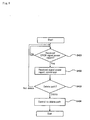
- FIG. 5 is a flowchart of an operation of the mobile communication system according to the first exemplary embodiment.
- base station 201 first monitors for reception of a CPICH signal received power report from a mobile station 101 (step S401).
- the CPICH signal received power report is a report of measurement information about the power of a CPICH signal received at mobile station 101.
- base station 201 converts the received signal power value in the report and then transmits the CPICH signal received power report to base station controller 106 (S402).
- Base station controller 106 receives the CPICH signal received power report and makes a path deletion determination (step S403).
- the path deletion determination is a determination as to whether a cell for which the received CPICH signal power report has been made should be removed from handover target cells.
- Base station controller 106 compares the received signal power value contained in the received CPICH signal power report with a stored threshold to make the determination. If base station controller 106 determines that the path should not be deleted, base station controller 106 returns to step S401.
- base station controller 106 determines that the path should be deleted, base station controller 106 performs path deletion control (step S404). In the path deletion control, base station controller 106 instructs base station 201 and mobile station 201 to delete the path.
- base station 201 similarly converts received signal power value contained in the CPICH signal received power report from mobile station 101 when a path is added.
- PT1 represents the transmission power of a CPICH signal of cell 202 and PT2 represents the transmission power of a CPICH signal of cell 203.
- PR1 represents the power of the CPICH signal received at mobile station 101 from cell 202 and PR2 represents the power of the CPICH signal received at mobile station 101 from cell 203.
- L1 represents path loss between cell 202 and mobile station 101 and L2 represents path loss between cell 203 and mobile station 101.
- the transmission power PT1 of the CPICH signal from cell 203 is higher than the transmission power PT2 of the CPICH signal from cell 202. It is assumed here that mobile station 101 is moving away from cell 202 toward cell 203.
- Measurement information provided by mobile station 101 includes the power PR1 of the received CPICH signal of cell 202 and the power PR2 of received CPICH signal of cell 203. As mobile station 101 moves, the received signal power values PR1 and PR2 change as shown in the chart of FIG. 1.
- the received signal power PR1 of cell 202 is higher than that of cell 203. This is because the CPICH signal of cell 202 is transmitted at higher power than the CPICH signal of cell 203. Actual losses on the paths of cells 202 and 203 are related as L1 ⁇ L2.
- Base station 201 corrects the received signal power values PR1 and PR2 from mobile station 101 to values reflecting estimated losses L1 and L2, that is, values indicating line conditions of the paths.
- the line quality of the path of cell 203 is still higher than that of the path of cell 202 at point A and therefore cell 202 should not be excluded from handover targets. Therefore, base station controller 106 does not yet delete cell 202 at this point.
- the exemplary embodiment can prevent the path of cell 202 having low loss from being improperly removed from handover targets. Consequently, degradation of communication quality caused by a difference in the transmission power of CPICH signals between cells can be reduced.
- base station controller 106 deletes cell 202.
- base stations 102, 103 convert the values of received signal power included in measurement information provided by mobile station 101 even when mobile station 101 is in the soft handover state shown in FIG. 2.
- Base station controller 106 determines a handover target cell on the basis of measurement information converted at base stations 102, 103.
- handover control according to the conditions of the path of each cell can be performed in the soft handover state and degradation of communication quality caused by a difference in transmission power of common channel signals between cells can be reduced.
- base station controller 106 instead of a base station, converts measurement information provided by mobile station 101.
- a basic configuration of the mobile communication system according to the second exemplary embodiment is the same as that of the first exemplary embodiment shown in FIGS. 2 and 3.
- controller 305 of base station 301 transfers measurement information including a measured value of the power of a received CPICH signal received from mobile station 101 through receiver 304 directly to base station controller 106 without conversion.
- base station controller 106 determines a handover target cell on the basis of measurement information received from mobile station 101 through the base station, base station controller 106 converts the received signal power included in the measurement information and uses the converted value.
- Conversion of received signal power in the second exemplary embodiment may be performed in a manner similar to conversion performed by base station 301 in the first exemplary embodiment.
- base station 301 uses RTWP (Received Total Wideband Power) information, in addition to the transmission power of CPICH signals, in conversion of received signal power reported by mobile station 101.
- RTWP Received Total Wideband Power
- RTWP is the total received signal power of a cell and can be an interference component of the reception signal at base station 301. Therefore, preferably a path with a high RPWP is removed from a set of handover target cells and a path with a low RTWP is left. To this end, the received signal power of a cell with a high RTWP may be reduced to a relatively low value and the received signal power of a cell with a lower RTWP may be increased to a relatively high value.
- controller 305 of base station 301 may measure the RPWP of a cell. If the RPWP is greater than a predetermined threshold, controller 305 performs, when converting the received signal power of the cell, conversion described with respect to the first exemplary embodiment and then subtracts a predetermined RTWP adjustment value.
- the received signal power in measurement information will more accurately reflect the line conditions of the path of each cell and therefore degradation of communication quality can be further reduced.
- a base station controller 106 may perform, in converting the received signal power of a cell, the conversion described with respect to the second exemplary embodiment and then subtract a predetermined RTWP adjustment value. In this case, base station 301 may report a measured RTWP value to base station controller 106.
- base station 301 uses SIR (Signal to Interference Ratio) information in addition to the transmission power of a CPICH signal in converting received signal power reported by mobile station 101.
- SIR Signal to Interference Ratio
- the SIR is the signal to interference power ratio.
- SIR SIR
- a cell with a high SIR is selected as a handover target and a cell with a low SIR is removed from a set of handover targets.
- the received signal power of a cell with a high SIR may be increased to a relatively high value and the received signal power of a cell with a low SIR may be reduced to a relatively low value.
- controller 305 of a base station 301 measures the SIR of a cell. If the SIR is smaller than or equal to a predetermined threshold, controller 305 may perform, in converting the received signal power of the cell, the conversion described with respect to the first exemplary embodiment and then subtract a predetermined SIR adjustment value.
- the received signal power in measurement information will more accurately reflect the line conditions of the path of each cell and therefore degradation of communication quality can be reduced.
- base station controller 106 may perform, in converting the received signal power of a cell, the conversion described with respect to the second exemplary embodiment and then subtract a predetermined SIR adjustment value.
- base station 301 may report a measured SIR value to base station controller 106.
- base station 301 performs the operation of the first exemplary embodiment and, in addition, adds or deletes uplink paths of multiple cells that use the same frequency, at the same time during control of handover. This can increase the received power of uplink dedicated channel signals.
- base station 301 When base station 301 receives from base station controller 106 an instruction to add a cell as a handover target, the base station establishes a path to mobile station 101 by using the cell and other cells that use the same frequency as that of the cell in the uplink direction. Thus, the multiple cells that use the same frequency are added as handover targets in the uplink direction.
- base station 301 receives an instruction from base station controller 106 to delete a cell from a set of handover targets, base station 301 deletes path to mobile station 101 that uses the cell and other cells that use the same frequency as the cell in the uplink direction.
- base station 301 when base station 301 is instructed to add or delete a cell to or from a set of handover target cells, base station 301 may add or delete at least one cell together with that cell in the uplink direction. Base station 301 may add or delete all the cells that use the same frequency to or from a set of handover target cells.
- base station 301 When establishing an uplink path, base station 301 makes predetermined settings in each functional section of base station 301 so that an uplink dedicated channel is made available. With this, an uplink path is created that passes through antenna 302, receiver 304 and controller 305.
- base station 301 can always receive signals through multiple paths for an uplink dedicated channel. As a result, the received power of uplink communication data can be increased and data losses and signal degradation can be reduced.
- FIG. 6 is a diagram for illustrating establishment of a path by a base station according to a fifth exemplary embodiment.
- base station 301 capable of forming three cells, cells #1 to #3, is shown. It is assumed here that base station 301 is requested by base station controller 106 to establish a path to a mobile station 101 using cell #1.
- base station 301 receives the request, base station 301 establishes uplink and downlink paths of cell #1 and also establishes only uplink paths for cells #2 and #3.
- FIG. 7 is a flowchart showing a path establishing operation performed in the mobile communication system according to the fifth exemplary embodiment.
- base station 301 first monitors for reception of a path establish request from base station controller 106 (step S601).
- base station 301 receives a path establish request
- base station 301 establishes uplink and downlink paths for a cell specified in the request (step S602).
- base station 301 determines whether there is another cell that uses the same frequency as the specified cell (step S603). If there is no other cell that uses the same frequency, base station 301 ends the process. If there is another cell, base station 301 establishes only an uplink path for that cell (step S604).
- base station 301 When base station 301 receives a path establish request that specifies a cell for which only an uplink paths has been established in response to a request for establishing another cell, base station 301 may establish both uplink and downlink paths for the specified cell. Thus, uplink and downlink paths for multiple cells that use the same frequency are established and only an uplink path is established for the other cell that uses the same frequency.
- base station 301 obtains uplink communication data by combining a signal of the uplink path using the cell specified by base station controller 106 with a signal of the uplink path using the other cell that uses the same frequency as that cell.
- mobile station 101 obtains downlink communication data from only a signal of the downlink path using the cell specified by base station controller 106.
- base station 301 transmits TPC information that instructs mobile station 101 to control transmission power only onto a downlink path using a cell specified by base station controller 106, thereby minimizing unnecessary transmission power.
- base station 301 When in this state base station 301 receives a path release request that specifies any cell, base station 301 goes into a state in which only the uplink path is established for the specified cell and does nothing for the other cells. When base station 301 receives a request for releasing the last cell for which uplink and downlink paths have been established, base station 301 releases the paths of the other cells for which only the uplink paths have been established at the same time.
- FIG. 8 is a flowchart showing the path release operation performed in the mobile communication system according to the fifth exemplary embodiment.
- base station 301 first monitors for a path release request from base station controller 106 (step S701).
- base station 301 receives a path release request
- base station 301 releases a downlink (for transmission) path specified in the request (step S702).
- base station 301 determines whether another cell that uses the same frequency as the specified cell should be released (step S703). If the path specified in the release request is the last path of the call in base station 301, another cell needs to be released. If the specified path is not the last path, another cell does not need to be released.
- base station 301 ends the process. If another cell that uses the same frequency does not need to be released, base station 301 ends the process. If another cell that uses the same frequency needs to be released, base station 301 releases all uplink paths of the cell (step S704). When all uplink paths are to be released, resources such as memory of controller 305 are also released at the same time.
- a base station When a base station receives a report of signal power of a common pilot channel of each cell received at a mobile station, the base station converts the received signal power in the report on the basis of the transmission power of the common pilot channel of each of the cells.
- a base station controller determines the cell to which the mobile station is to be connected on the basis of the received signal power of the common pilot channel in each cell.
Landscapes
- Engineering & Computer Science (AREA)
- Computer Networks & Wireless Communication (AREA)
- Signal Processing (AREA)
- Mobile Radio Communication Systems (AREA)
Applications Claiming Priority (1)
| Application Number | Priority Date | Filing Date | Title |
|---|---|---|---|
| JP2006276676A JP2008098847A (ja) | 2006-10-10 | 2006-10-10 | 移動通信システムおよびハンドオーバ制御方法 |
Publications (3)
| Publication Number | Publication Date |
|---|---|
| EP1912463A2 true EP1912463A2 (fr) | 2008-04-16 |
| EP1912463A3 EP1912463A3 (fr) | 2011-04-13 |
| EP1912463B1 EP1912463B1 (fr) | 2015-07-22 |
Family
ID=38983208
Family Applications (1)
| Application Number | Title | Priority Date | Filing Date |
|---|---|---|---|
| EP07253587.5A Ceased EP1912463B1 (fr) | 2006-10-10 | 2007-09-10 | Système de communication mobile et procédé de contrôle de transfert |
Country Status (4)
| Country | Link |
|---|---|
| US (1) | US8107959B2 (fr) |
| EP (1) | EP1912463B1 (fr) |
| JP (1) | JP2008098847A (fr) |
| CN (1) | CN101163338A (fr) |
Cited By (2)
| Publication number | Priority date | Publication date | Assignee | Title |
|---|---|---|---|---|
| EP2950590A1 (fr) * | 2014-05-26 | 2015-12-02 | Nokia Technologies OY | Sélection de dispositif de proximité |
| EP2315477A4 (fr) * | 2008-08-11 | 2016-06-29 | Ntt Docomo Inc | Dispositif utilisateur, station de base radio, et procédé |
Families Citing this family (7)
| Publication number | Priority date | Publication date | Assignee | Title |
|---|---|---|---|---|
| US20090086691A1 (en) * | 2007-10-01 | 2009-04-02 | Qual Comm Incorporated | System and method to facilitate handling of access terminals camped onto an access point base station |
| CN102037767B (zh) * | 2008-05-20 | 2014-05-14 | 株式会社Ntt都科摩 | 移动通信方法以及无线基站 |
| US9357462B2 (en) * | 2008-12-24 | 2016-05-31 | Samsung Electronics Co., Ltd. | Apparatus and method for changing serving cell in a high speed wireless communication system |
| CN101932016A (zh) * | 2009-06-18 | 2010-12-29 | 中兴通讯股份有限公司 | 一种在基站间切换的方法及装置 |
| US8867494B2 (en) * | 2009-11-09 | 2014-10-21 | Qualcomm Incorporated | System and method for single frequency dual cell high speed downlink packet access |
| US10470116B1 (en) * | 2014-05-05 | 2019-11-05 | Sprint Spectrum L.P. | Systems and methods for determining an access node for a wireless device |
| JP5680247B1 (ja) * | 2014-06-06 | 2015-03-04 | ソフトバンクモバイル株式会社 | 無線基地局及びプログラム |
Citations (5)
| Publication number | Priority date | Publication date | Assignee | Title |
|---|---|---|---|---|
| EP1235454A2 (fr) | 2001-02-21 | 2002-08-28 | Nec Corporation | Système cellulaire, station de base, station mobile et méthode de contrôle de communication associé |
| US20050070285A1 (en) | 2003-09-29 | 2005-03-31 | Telefonaktiebolaget Lm Ericsson (Publ) | Handover for use with adaptive antennas |
| US20050118993A1 (en) | 2002-04-05 | 2005-06-02 | Pierre Roux | Method for controlling radio resources assigned to a communication between a mobile terminal and a cellular infrastructure, and facilities |
| JP2006054625A (ja) | 2004-08-11 | 2006-02-23 | Nec Corp | 移動通信システム、移動通信端末及びそれらに用いるハンドオーバ制御方法並びにそのプログラム |
| JP2006276676A (ja) | 2005-03-04 | 2006-10-12 | Ricoh Co Ltd | タンデム画像形成装置 |
Family Cites Families (19)
| Publication number | Priority date | Publication date | Assignee | Title |
|---|---|---|---|---|
| JP3078216B2 (ja) * | 1995-12-13 | 2000-08-21 | 株式会社エヌ・ティ・ティ・ドコモ | 基地局選択方法 |
| JPH09327059A (ja) * | 1996-06-07 | 1997-12-16 | N T T Ido Tsushinmo Kk | Cdma移動通信システムにおけるセル選択方法およびその基地局装置と移動局装置 |
| JP3382783B2 (ja) * | 1996-07-11 | 2003-03-04 | 株式会社エヌ・ティ・ティ・ドコモ | 移動通信チャネル切換制御システム及び移動通信チャネル切換制御方法 |
| US6026301A (en) * | 1996-12-17 | 2000-02-15 | Northern Telecom Limited | Method for hard handoff in a CDMA cellular environment |
| JPH11155165A (ja) * | 1997-11-21 | 1999-06-08 | Toshiba Corp | 移動通信システム、基地局装置および制御局装置 |
| KR100413418B1 (ko) * | 1998-07-10 | 2004-02-14 | 엘지전자 주식회사 | 역방향링크의독립적소프트핸드오프제어방법 |
| KR100311509B1 (ko) * | 1998-12-22 | 2001-11-15 | 서평원 | 주파수간핸드오프제어방법 |
| US6326841B1 (en) * | 1999-04-16 | 2001-12-04 | Nokia Telecommunications, Oy | Method and apparatus for compensating for loss or RF output power from the isolation port of a hybrid coupler |
| EP1117269A1 (fr) | 2000-01-13 | 2001-07-18 | TELEFONAKTIEBOLAGET LM ERICSSON (publ) | Procédé et dispositifs pour procédures de commutation associée améliorées dans des systèmes de communication mobile |
| US20030171118A1 (en) * | 2001-06-06 | 2003-09-11 | Kazuyuki Miya | Cellular radio transmission apparatus and cellular radio transmission method |
| JP4008301B2 (ja) * | 2002-08-01 | 2007-11-14 | 株式会社エヌ・ティ・ティ・ドコモ | 基地局接続方法、無線ネットワーク制御装置及び移動局 |
| JP2004336635A (ja) | 2003-05-12 | 2004-11-25 | Nec Corp | 移動通信システムとその送信制御方法 |
| JP5021935B2 (ja) * | 2003-06-25 | 2012-09-12 | 日本電気株式会社 | 移動通信システムおよびアクセス制御方法 |
| EP1499147A1 (fr) | 2003-07-17 | 2005-01-19 | Mitsubishi Electric Information Technology Centre Europe B.V. | Transfert douce dépendant de trafic dans un réseau AMRC |
| JP4400733B2 (ja) * | 2004-03-31 | 2010-01-20 | 日本電気株式会社 | 移動体通信システムの制御方法 |
| JP4659385B2 (ja) * | 2004-04-19 | 2011-03-30 | 三菱電機株式会社 | ハンドオーバ制御方法および移動局 |
| JP4530148B2 (ja) | 2004-11-30 | 2010-08-25 | 日本電気株式会社 | Cdma移動通信システムと基地局およびアクティブセット選択方法 |
| JP4559240B2 (ja) * | 2005-01-13 | 2010-10-06 | 株式会社エヌ・ティ・ティ・ドコモ | 移動通信システム、無線基地局、無線回線制御局及び電力制御方法 |
| US7269422B2 (en) * | 2005-07-08 | 2007-09-11 | Telefonaktiebolaget Lm Ericsson (Publ) | Wireless telecommunications with adjustment of uplink power level |
-
2006
- 2006-10-10 JP JP2006276676A patent/JP2008098847A/ja active Pending
-
2007
- 2007-09-06 US US11/850,950 patent/US8107959B2/en active Active
- 2007-09-10 EP EP07253587.5A patent/EP1912463B1/fr not_active Ceased
- 2007-10-10 CN CNA2007101631542A patent/CN101163338A/zh active Pending
Patent Citations (5)
| Publication number | Priority date | Publication date | Assignee | Title |
|---|---|---|---|---|
| EP1235454A2 (fr) | 2001-02-21 | 2002-08-28 | Nec Corporation | Système cellulaire, station de base, station mobile et méthode de contrôle de communication associé |
| US20050118993A1 (en) | 2002-04-05 | 2005-06-02 | Pierre Roux | Method for controlling radio resources assigned to a communication between a mobile terminal and a cellular infrastructure, and facilities |
| US20050070285A1 (en) | 2003-09-29 | 2005-03-31 | Telefonaktiebolaget Lm Ericsson (Publ) | Handover for use with adaptive antennas |
| JP2006054625A (ja) | 2004-08-11 | 2006-02-23 | Nec Corp | 移動通信システム、移動通信端末及びそれらに用いるハンドオーバ制御方法並びにそのプログラム |
| JP2006276676A (ja) | 2005-03-04 | 2006-10-12 | Ricoh Co Ltd | タンデム画像形成装置 |
Cited By (2)
| Publication number | Priority date | Publication date | Assignee | Title |
|---|---|---|---|---|
| EP2315477A4 (fr) * | 2008-08-11 | 2016-06-29 | Ntt Docomo Inc | Dispositif utilisateur, station de base radio, et procédé |
| EP2950590A1 (fr) * | 2014-05-26 | 2015-12-02 | Nokia Technologies OY | Sélection de dispositif de proximité |
Also Published As
| Publication number | Publication date |
|---|---|
| US20080085708A1 (en) | 2008-04-10 |
| EP1912463B1 (fr) | 2015-07-22 |
| EP1912463A3 (fr) | 2011-04-13 |
| JP2008098847A (ja) | 2008-04-24 |
| CN101163338A (zh) | 2008-04-16 |
| US8107959B2 (en) | 2012-01-31 |
Similar Documents
| Publication | Publication Date | Title |
|---|---|---|
| US8107959B2 (en) | Mobile communication system and handover control method | |
| US7693536B2 (en) | Base station, mobile station and control method therefor | |
| US5564075A (en) | Method and system for controlling the power at which an access packet is sent by a mobile in a mobile radio system | |
| US7190957B2 (en) | Base station connection method, radio network controller, and mobile station | |
| KR100432565B1 (ko) | 셀룰라 통신 시스템에서 순방향 링크 핸드오프 경계를역방향 링크 핸드오프 경계와 균형을 맞추기 위한 방법 및장치 | |
| JP4426116B2 (ja) | 無線通信システムの適応電力制御 | |
| JP3212019B2 (ja) | Cdma移動通信システムにおける送信電力制御方法およびcdma移動通信システム | |
| EP1128577A1 (fr) | Dispositif de radiocommunication et procede de radiocommunication | |
| EP1185120A1 (fr) | Dispositif de station de base et dispositif de commande de transfert intercellulaire | |
| US8160630B2 (en) | Method and arrangement for controlling transmission power and a network element | |
| EP1330930A1 (fr) | Interruption momentanee de service pour transfert de donnees a grande vitesse | |
| EP1096822B1 (fr) | Appareil et procédé pour transmission/réception en TDMA-TDD | |
| KR101140236B1 (ko) | 무선 이동통신 네트워크, 및 모바일 사용자 단말과 접속을위해 기지국 안테나들을 선택하는 방법 | |
| US8189533B2 (en) | Calculation of a destination time alignment value to be used by a user equipment in a destination cell after a handover | |
| EP1298816B1 (fr) | Procédé de commande de puissance de transmission et station mobile | |
| KR100433898B1 (ko) | 부호분할다중접속 이동통신시스템에서 소프트 핸드오버결정장치 및 방법 | |
| EP1185124A1 (fr) | Appareil pour station mobile et procede de radiocommunication | |
| JP2004208177A (ja) | ハンドオーバ方法及び無線通信装置 | |
| US20110237292A1 (en) | Radio communication apparatus and transmission power control method | |
| KR20050059206A (ko) | 이동국 신호에 의해 제 2 기지국에서 발생하는 간섭에 대한평가를 기반으로 수행되는 이동국과 제 1 기지국 간의통신 적응 | |
| JP2006129134A (ja) | 無線通信装置、送信電力制御方法及び送信電力制御プログラム | |
| US7171232B2 (en) | Method of selecting a cell to connect by radio with a mobile station and a mobile communications terminal therefor | |
| HK1086398A (en) | Base station, mobile station and power control method according to movement of the mobile station |
Legal Events
| Date | Code | Title | Description |
|---|---|---|---|
| PUAI | Public reference made under article 153(3) epc to a published international application that has entered the european phase |
Free format text: ORIGINAL CODE: 0009012 |
|
| AK | Designated contracting states |
Kind code of ref document: A2 Designated state(s): AT BE BG CH CY CZ DE DK EE ES FI FR GB GR HU IE IS IT LI LT LU LV MC MT NL PL PT RO SE SI SK TR |
|
| AX | Request for extension of the european patent |
Extension state: AL BA HR MK RS |
|
| PUAL | Search report despatched |
Free format text: ORIGINAL CODE: 0009013 |
|
| AK | Designated contracting states |
Kind code of ref document: A3 Designated state(s): AT BE BG CH CY CZ DE DK EE ES FI FR GB GR HU IE IS IT LI LT LU LV MC MT NL PL PT RO SE SI SK TR |
|
| AX | Request for extension of the european patent |
Extension state: AL BA HR MK RS |
|
| 17P | Request for examination filed |
Effective date: 20111012 |
|
| AKX | Designation fees paid |
Designated state(s): DE FR GB |
|
| 17Q | First examination report despatched |
Effective date: 20131220 |
|
| REG | Reference to a national code |
Ref country code: DE Ref legal event code: R079 Ref document number: 602007042221 Country of ref document: DE Free format text: PREVIOUS MAIN CLASS: H04Q0007380000 Ipc: H04W0036300000 |
|
| RIC1 | Information provided on ipc code assigned before grant |
Ipc: H04W 36/30 20090101AFI20150121BHEP |
|
| GRAP | Despatch of communication of intention to grant a patent |
Free format text: ORIGINAL CODE: EPIDOSNIGR1 |
|
| INTG | Intention to grant announced |
Effective date: 20150312 |
|
| GRAS | Grant fee paid |
Free format text: ORIGINAL CODE: EPIDOSNIGR3 |
|
| GRAA | (expected) grant |
Free format text: ORIGINAL CODE: 0009210 |
|
| AK | Designated contracting states |
Kind code of ref document: B1 Designated state(s): DE FR GB |
|
| REG | Reference to a national code |
Ref country code: GB Ref legal event code: FG4D |
|
| REG | Reference to a national code |
Ref country code: DE Ref legal event code: R096 Ref document number: 602007042221 Country of ref document: DE |
|
| REG | Reference to a national code |
Ref country code: DE Ref legal event code: R097 Ref document number: 602007042221 Country of ref document: DE |
|
| PLBE | No opposition filed within time limit |
Free format text: ORIGINAL CODE: 0009261 |
|
| STAA | Information on the status of an ep patent application or granted ep patent |
Free format text: STATUS: NO OPPOSITION FILED WITHIN TIME LIMIT |
|
| 26N | No opposition filed |
Effective date: 20160425 |
|
| REG | Reference to a national code |
Ref country code: FR Ref legal event code: PLFP Year of fee payment: 10 |
|
| REG | Reference to a national code |
Ref country code: FR Ref legal event code: PLFP Year of fee payment: 11 |
|
| PGFP | Annual fee paid to national office [announced via postgrant information from national office to epo] |
Ref country code: FR Payment date: 20170810 Year of fee payment: 11 Ref country code: GB Payment date: 20170906 Year of fee payment: 11 Ref country code: DE Payment date: 20170905 Year of fee payment: 11 |
|
| REG | Reference to a national code |
Ref country code: DE Ref legal event code: R119 Ref document number: 602007042221 Country of ref document: DE |
|
| GBPC | Gb: european patent ceased through non-payment of renewal fee |
Effective date: 20180910 |
|
| PG25 | Lapsed in a contracting state [announced via postgrant information from national office to epo] |
Ref country code: DE Free format text: LAPSE BECAUSE OF NON-PAYMENT OF DUE FEES Effective date: 20190402 |
|
| PG25 | Lapsed in a contracting state [announced via postgrant information from national office to epo] |
Ref country code: FR Free format text: LAPSE BECAUSE OF NON-PAYMENT OF DUE FEES Effective date: 20180930 |
|
| PG25 | Lapsed in a contracting state [announced via postgrant information from national office to epo] |
Ref country code: GB Free format text: LAPSE BECAUSE OF NON-PAYMENT OF DUE FEES Effective date: 20180910 |