EP1912840B1 - Frein electromecanique - Google Patents
Frein electromecanique Download PDFInfo
- Publication number
- EP1912840B1 EP1912840B1 EP06763514.4A EP06763514A EP1912840B1 EP 1912840 B1 EP1912840 B1 EP 1912840B1 EP 06763514 A EP06763514 A EP 06763514A EP 1912840 B1 EP1912840 B1 EP 1912840B1
- Authority
- EP
- European Patent Office
- Prior art keywords
- brake
- motor shaft
- cover
- electric motor
- rotation
- Prior art date
- Legal status (The legal status is an assumption and is not a legal conclusion. Google has not performed a legal analysis and makes no representation as to the accuracy of the status listed.)
- Not-in-force
Links
Images
Classifications
-
- F—MECHANICAL ENGINEERING; LIGHTING; HEATING; WEAPONS; BLASTING
- F16—ENGINEERING ELEMENTS AND UNITS; GENERAL MEASURES FOR PRODUCING AND MAINTAINING EFFECTIVE FUNCTIONING OF MACHINES OR INSTALLATIONS; THERMAL INSULATION IN GENERAL
- F16D—COUPLINGS FOR TRANSMITTING ROTATION; CLUTCHES; BRAKES
- F16D65/00—Parts or details
- F16D65/14—Actuating mechanisms for brakes; Means for initiating operation at a predetermined position
- F16D65/16—Actuating mechanisms for brakes; Means for initiating operation at a predetermined position arranged in or on the brake
- F16D65/18—Actuating mechanisms for brakes; Means for initiating operation at a predetermined position arranged in or on the brake adapted for drawing members together, e.g. for disc brakes
-
- B—PERFORMING OPERATIONS; TRANSPORTING
- B60—VEHICLES IN GENERAL
- B60T—VEHICLE BRAKE CONTROL SYSTEMS OR PARTS THEREOF; BRAKE CONTROL SYSTEMS OR PARTS THEREOF, IN GENERAL; ARRANGEMENT OF BRAKING ELEMENTS ON VEHICLES IN GENERAL; PORTABLE DEVICES FOR PREVENTING UNWANTED MOVEMENT OF VEHICLES; VEHICLE MODIFICATIONS TO FACILITATE COOLING OF BRAKES
- B60T13/00—Transmitting braking action from initiating means to ultimate brake actuator with power assistance or drive; Brake systems incorporating such transmitting means, e.g. air-pressure brake systems
- B60T13/74—Transmitting braking action from initiating means to ultimate brake actuator with power assistance or drive; Brake systems incorporating such transmitting means, e.g. air-pressure brake systems with electrical assistance or drive
- B60T13/741—Transmitting braking action from initiating means to ultimate brake actuator with power assistance or drive; Brake systems incorporating such transmitting means, e.g. air-pressure brake systems with electrical assistance or drive acting on an ultimate actuator
-
- F—MECHANICAL ENGINEERING; LIGHTING; HEATING; WEAPONS; BLASTING
- F16—ENGINEERING ELEMENTS AND UNITS; GENERAL MEASURES FOR PRODUCING AND MAINTAINING EFFECTIVE FUNCTIONING OF MACHINES OR INSTALLATIONS; THERMAL INSULATION IN GENERAL
- F16D—COUPLINGS FOR TRANSMITTING ROTATION; CLUTCHES; BRAKES
- F16D2121/00—Type of actuator operation force
- F16D2121/18—Electric or magnetic
- F16D2121/24—Electric or magnetic using motors
-
- F—MECHANICAL ENGINEERING; LIGHTING; HEATING; WEAPONS; BLASTING
- F16—ENGINEERING ELEMENTS AND UNITS; GENERAL MEASURES FOR PRODUCING AND MAINTAINING EFFECTIVE FUNCTIONING OF MACHINES OR INSTALLATIONS; THERMAL INSULATION IN GENERAL
- F16D—COUPLINGS FOR TRANSMITTING ROTATION; CLUTCHES; BRAKES
- F16D2123/00—Multiple operation forces
-
- F—MECHANICAL ENGINEERING; LIGHTING; HEATING; WEAPONS; BLASTING
- F16—ENGINEERING ELEMENTS AND UNITS; GENERAL MEASURES FOR PRODUCING AND MAINTAINING EFFECTIVE FUNCTIONING OF MACHINES OR INSTALLATIONS; THERMAL INSULATION IN GENERAL
- F16D—COUPLINGS FOR TRANSMITTING ROTATION; CLUTCHES; BRAKES
- F16D2125/00—Components of actuators
- F16D2125/18—Mechanical mechanisms
- F16D2125/20—Mechanical mechanisms converting rotation to linear movement or vice versa
- F16D2125/34—Mechanical mechanisms converting rotation to linear movement or vice versa acting in the direction of the axis of rotation
-
- F—MECHANICAL ENGINEERING; LIGHTING; HEATING; WEAPONS; BLASTING
- F16—ENGINEERING ELEMENTS AND UNITS; GENERAL MEASURES FOR PRODUCING AND MAINTAINING EFFECTIVE FUNCTIONING OF MACHINES OR INSTALLATIONS; THERMAL INSULATION IN GENERAL
- F16D—COUPLINGS FOR TRANSMITTING ROTATION; CLUTCHES; BRAKES
- F16D2127/00—Auxiliary mechanisms
- F16D2127/06—Locking mechanisms, e.g. acting on actuators, on release mechanisms or on force transmission mechanisms
-
- F—MECHANICAL ENGINEERING; LIGHTING; HEATING; WEAPONS; BLASTING
- F16—ENGINEERING ELEMENTS AND UNITS; GENERAL MEASURES FOR PRODUCING AND MAINTAINING EFFECTIVE FUNCTIONING OF MACHINES OR INSTALLATIONS; THERMAL INSULATION IN GENERAL
- F16D—COUPLINGS FOR TRANSMITTING ROTATION; CLUTCHES; BRAKES
- F16D2127/00—Auxiliary mechanisms
- F16D2127/08—Self-amplifying or de-amplifying mechanisms
-
- F—MECHANICAL ENGINEERING; LIGHTING; HEATING; WEAPONS; BLASTING
- F16—ENGINEERING ELEMENTS AND UNITS; GENERAL MEASURES FOR PRODUCING AND MAINTAINING EFFECTIVE FUNCTIONING OF MACHINES OR INSTALLATIONS; THERMAL INSULATION IN GENERAL
- F16D—COUPLINGS FOR TRANSMITTING ROTATION; CLUTCHES; BRAKES
- F16D2127/00—Auxiliary mechanisms
- F16D2127/08—Self-amplifying or de-amplifying mechanisms
- F16D2127/085—Self-amplifying or de-amplifying mechanisms having additional fluid pressure elements
-
- F—MECHANICAL ENGINEERING; LIGHTING; HEATING; WEAPONS; BLASTING
- F16—ENGINEERING ELEMENTS AND UNITS; GENERAL MEASURES FOR PRODUCING AND MAINTAINING EFFECTIVE FUNCTIONING OF MACHINES OR INSTALLATIONS; THERMAL INSULATION IN GENERAL
- F16D—COUPLINGS FOR TRANSMITTING ROTATION; CLUTCHES; BRAKES
- F16D2127/00—Auxiliary mechanisms
- F16D2127/08—Self-amplifying or de-amplifying mechanisms
- F16D2127/10—Self-amplifying or de-amplifying mechanisms having wedging elements
Definitions
- the invention relates to an electromechanical brake having the features of claim 1.
- Such brakes are known per se.
- the brakes For their operation, d. H. for pressing a friction brake lining against a rotatable brake body to be braked, the brakes have an electromechanical actuating device with an electric motor and a rotation / translation conversion gear, via which the friction brake lining can be pressed against the brake body with the electric motor.
- the electric motor and the rotation / translation conversion gear is often interposed a reduction gear).
- As a rotation / translation conversion gear helical gear are common, but there are other gear, such as rack and pinion or with the electric motor via a reduction gear cam which presses the friction brake pad against the brake body, to implement the rotary drive movement of the electric motor in a translational movement for pressing the friction brake lining against the brake body into consideration.
- An electromagnet in place of the electric motor is conceivable.
- the brake body is in the case of a disc brake a brake disc, in the case of a drum brake a brake drum.
- an example of such an electromechanical brake discloses the DE 102 55 192 A1 ,
- a parking brake parking brake
- the known brake on a switchable freewheel which locks in a switched-on position, a motor shaft of the electric motor against rotation in a release direction of the brake.
- the blocking can be done directly on the motor shaft or indirectly, for example on a transmission shaft.
- the motor shaft In an operating or application direction of the brake, the motor shaft is rotatable even when the freewheel, so that the brake press, but can not solve.
- the freewheel is switched off, the motor shaft is rotatable in both directions of rotation, and the brake can be actuated and released as a service brake.
- the known brake of the freewheel is coaxially flanged to a housing in which the electric motor and the rotation / translation conversion gear are housed.
- An electromechanical brake in which a brake pad can not be pressed by an electric motor but by a spindle drive against a brake disc.
- a nut of the spindle drive via a second spindle is axially supported and blocked by means of a permanent magnet brake against rotation.
- the permanent magnet brake is energized.
- a reaction force of the pressure force of the brake pad against the brake disc causes in this case that the spindle of the spindle drive in the axial direction of the brake disc until the brake pads are free again or rest only with low pressure. Even if the spindle drive fails, the brake can be released by energizing the permanent magnet brake.
- the brake according to the invention comprises an electric motor with a housing, in which a motor shaft carrying a rotor is rotatably mounted and at the one end of which a cover is attached. Furthermore, a rotation / translation conversion gear, a friction brake pad which is pressed against a brake body with the electric motor via the rotation / translation conversion gear to actuate the brake, and a switchable freewheel, with clamping or locking elements in an annular Space between the motor shaft and the lid are arranged distributed around the motor shaft.
- the distributed arrangement is such that the freewheel in a switched-on position allows rotation of the motor shaft of the electric motor in the application direction of the brake and locks against rotation in the release direction of the brake.
- the cover forms a bearing plate for the motor shaft of the electric motor and the freewheel is housed on or in the lid.
- This integrated construction of the cover of the housing for the electric motor reduces the number of individual components and at the same time the assembly effort of the brake according to the invention.
- a positional accuracy of the freewheel in relation to the motor shaft is increased, since the bearing for the motor shaft is arranged in the cover, or in which the freewheel is housed.
- a high accuracy of the axial position of the motor shaft with respect to the freewheel can be kept.
- the high axial accuracy is important to ensure reliable freewheeling and to prevent inadvertent freewheel switching.
- the invention ensures exact compliance with an installation angle of the freewheel.
- the invention enables a compact construction of the brake.
- the brake according to the invention may have a self-reinforcing device which converts a frictional force exerted on the friction brake lining pressed against it by the rotating brake body into a pressing force which presses the friction brake lining against the brake body in addition to a pressing force applied by the actuating device and thereby increases the braking force.
- a self-reinforcing device for example, wedge or ramp mechanisms or lever mechanisms come into consideration.
- Other, for example, hydraulic self-reinforcing devices are conceivable.
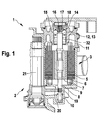
- the illustrated in the drawing, generally designated 1 brake according to the invention is a disc brake. It has an electromechanical actuator 2 with an electric motor 3, a yet to be explained multi-stage gear and reduction gear and a rack gear or other rotation / Tranlsations conversion gear.
- the electric motor 3, the reduction gear and the rotation / translation conversion gear form an electromechanical actuating device of the brake 1.
- the electric motor 3 has a stator 5 with stator windings 6 and a rotor 7 on a motor shaft 8.
- the electric motor 3 is an electronically commutated DC motor (brushless BLDC motor), which is not mandatory for the invention.
- the electric motor 3 is housed in a housing 9, in which the stator 5 is pressed or fixed in another way.
- the motor shaft 8 is at one end with a floating bearing 10, d. H. rotatably mounted in the housing 9 with axial play.
- a roller bearing is used as a movable bearing 10.
- the housing 9 is closed with a lid 11, which is made for example of steel or a material comparable strength.
- the lid 11 forms a bearing plate of a fixed bearing 12 of the electric motor 3.
- a ball bearing with balls 13 is selected in the illustrated and described embodiment of the invention, which are rotatably supported in a ball cage 14.
- An inner race of the fixed bearing 12 is bisected in a radial plane to the motor shaft 8: A half of the inner bearing ring is of a ring at an annular stage the motor shaft 8 ground tread 16 formed with a circular cross-section.
- a second running surface 17, also with a circular cross-section, is formed on a nut 18, which is screwed onto the motor shaft 8.
- the tread 16 of Motor shaft 8 and the running surface 17 of the nut 18 complement each other to a circumferential groove with a circular cross section and the inner bearing ring 16, 17 of the fixed bearing 12.
- the nut 18 is, for example a screw locking lacquer secured against rotation on the motor shaft 8.
- the transmission shaft 21 can follow other gear stages and an actuated in any way application mechanism for a wheel brake.
- the housing 9, in which the electric motor 3 is housed, is part of a brake caliper, not shown, of the disc brake designed as a brake 1.
- the housing 9 may also be mounted on the brake caliper.
- the caliper, of which only a fraction, namely the housing 9, is shown, is formed in a conventional manner as a floating caliper, ie it is guided transversely to a brake disc, not shown, slidably.
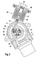
- a switchable freewheel 31 is housed.
- the freewheel 31 is designed as a clamping roller freewheel with rollers 32 as clamping or locking elements. Other types of freewheel 31 are possible.
- the rollers 32 are arranged distributed around the motor shaft 8 of the electric motor 3 around. They are received in recesses of a roller cage 33 which is arranged in an annular space between the motor shaft 8 and the lid 11.
- Spring elements 34 which are also arranged in the recesses of the roller cage 33, act on the rollers 32 in the circumferential direction, so that the rollers 32 are lifted from the motor shaft 8.
- the rollers 32 roll in pockets 35 in the axial bore of the lid 11.
- a base of the pockets 35 forms a running surface for the rollers 32.
- the running surfaces forming the base surfaces of the pockets 35 extend helically to the motor shaft 8.
- roller cage 33 If the roller cage 33 is rotated back into its initial position and the rollers 32 are lifted by the spring elements 34 of the motor shaft 8, the freewheel 31 is turned off and the motor shaft 8 freely rotatable in both directions of rotation.
- the freewheel 31 has an electromagnet 36 with a winding 37 and an armature 38.
- a housing 39 of the electromagnet 36 is integral with the lid 11 of the housing 9 of the electric motor 3.
- the solenoid 36 switches the freewheel 31 via a plunger 41, which is arranged tangentially to the roller cage 33 of the freewheel 31.
- the plunger 41 engages a protruding radially outward from the roller cage 33 cam 42 against whose opposite side a spring element 43 in the form of a helical compression spring pushes, which is housed in a pocket of the lid 11 outside of the roller cage 33 and in the lid 11 supported.
- the armature 38 is tightened and presses on the plunger 41 against the cam 42 of the roller cage 33 of the freewheel 31.
- the roller cage 33 is thereby rotated as described above in the on position.
- the brake 1 can be further tightened in the switched-on position of the freewheel 31, but not solved.
- the brake 1 If the brake 1 is or is actuated when the freewheel 31 is switched on, a mechanical tension is built up which keeps the rollers 32 of the freewheel 31 clamped between the motor shaft 8 and the cover 11, even if the electromagnet 36 is no longer energized.
- the brake 1 is thus held de-energized in the actuated position and can thereby be used as a parking brake.
- To release the actuated brake 1 is applied to the electric motor 3, whereby the mechanical bias dissolves, so that the spring element 43, the roller cage 33 of the freewheel 31 rotates back to the off position.
- the motor shaft 8 is now freely rotatable, the brake 1 can be released and used as a service brake.
- the lid 11 with the pockets 35 for the rollers 32 which cooperates with the rollers 32 and locks the motor shaft 8 against rotation in the release direction of the brake 1 when the freewheel 31 together with the rollers 32 forms part of a blockage of the freewheel 31st
- the cover 11 of the housing 9 contains all electrical lines of both the electric motor 3 and the electromagnet 36, the electrical lines are in one or more, not visible in the drawing electrical Connectors led together. This has the advantage of a simple electrical connection of the electrical components of the brake 1 according to the invention.
Landscapes
- Engineering & Computer Science (AREA)
- Mechanical Engineering (AREA)
- General Engineering & Computer Science (AREA)
- Transportation (AREA)
- Braking Arrangements (AREA)
- Rolling Contact Bearings (AREA)
Claims (7)
- Frein électromécanique, comprenant un moteur électrique (3) doté d'un carter (9) dans lequel un arbre de moteur (8) supportant un rotor (7) est disposé de façon à pouvoir tourner et au niveau de l'extrémité frontale duquel un cache (11) est placé, une transmission de conversion de rotation/translation, une garniture de frein à friction pouvant être comprimée pour actionner le frein (1) contre un corps de frein avec le moteur électrique (3), via la transmission de conversion de rotation/translation, et une roue libre (31) pouvant être connectée, avec des éléments de serrage ou de blocage (32) disposés de façon à être répartis dans un espace intermédiaire de forme annulaire situé entre l'arbre de moteur (8) et le cache (11) et entourant l'arbre de moteur (8) de telle sorte que la roue libre (31) permet, dans une position connectée, la rotation de l'arbre de moteur (8) du moteur électrique (3) dans la direction de serrage du frein (1) et bloque le frein (1) contre une rotation dans la direction de relâchement, le cache (11) formant un panneau de palier de roulement pour l'arbre de moteur (8) du moteur électrique (3) et la roue libre (31) étant logée au niveau du cache (11) ou dans celui-ci.
- Frein électromécanique selon la revendication 1, caractérisé en ce que le cache (11) forme une bague de palier de roulement (15) pour un palier de roulement (12) de l'arbre de moteur (8).
- Frein électromécanique selon la revendication 1, caractérisé en ce qu'au moins une partie (16) d'une bague de palier de roulement (16, 17) du palier de roulement (12) de l'arbre de moteur (8) est un composant réalisé d'un seul tenant de l'arbre de moteur (8) et que cette partie (16) de la bague de palier de roulement (16, 17) fixe l'arbre de moteur (8) dans une direction axiale.
- Frein électromécanique selon la revendication 1, caractérisé en ce que le cache (11) fait partie d'un blocage de la roue libre (31).
- Frein électromécanique selon la revendication 1, caractérisé en ce que le cache (11) comporte toutes les liaisons électriques du moteur électrique (3) et de la roue libre (31).
- Frein électromécanique selon la revendication 1, caractérisé en ce que le frein (1) est un frein à disque et que le carter (9) fait partie d'un étrier du frein (1).
- Frein électromécanique selon la revendication 1, caractérisé en ce que le cache (11) forme un carter (39) pour la roue libre (31).
Applications Claiming Priority (2)
| Application Number | Priority Date | Filing Date | Title |
|---|---|---|---|
| DE102005035607A DE102005035607A1 (de) | 2005-07-29 | 2005-07-29 | Elektromechanische Bremse |
| PCT/EP2006/062910 WO2007012515A1 (fr) | 2005-07-29 | 2006-06-06 | Frein electromecanique |
Publications (2)
| Publication Number | Publication Date |
|---|---|
| EP1912840A1 EP1912840A1 (fr) | 2008-04-23 |
| EP1912840B1 true EP1912840B1 (fr) | 2014-10-22 |
Family
ID=36808781
Family Applications (1)
| Application Number | Title | Priority Date | Filing Date |
|---|---|---|---|
| EP06763514.4A Not-in-force EP1912840B1 (fr) | 2005-07-29 | 2006-06-06 | Frein electromecanique |
Country Status (6)
| Country | Link |
|---|---|
| US (1) | US8020675B2 (fr) |
| EP (1) | EP1912840B1 (fr) |
| JP (1) | JP4886780B2 (fr) |
| CN (1) | CN101233031B (fr) |
| DE (1) | DE102005035607A1 (fr) |
| WO (1) | WO2007012515A1 (fr) |
Cited By (1)
| Publication number | Priority date | Publication date | Assignee | Title |
|---|---|---|---|---|
| DE102022121851A1 (de) | 2022-08-30 | 2024-02-29 | Schaeffler Technologies AG & Co. KG | Lageranordnung mit schaltbarem Freilauf, Linearaktuator und Verfahren zum Betrieb eines Linearaktuators |
Families Citing this family (10)
| Publication number | Priority date | Publication date | Assignee | Title |
|---|---|---|---|---|
| DE102006000746A1 (de) * | 2006-01-04 | 2007-07-05 | Robert Bosch Gmbh | Schaltbarer Freilauf und elektromechanische Fahrzeugbremse mit dem schaltbaren Freilauf |
| US20110067961A1 (en) * | 2007-09-19 | 2011-03-24 | Johannes Andrianus Maria Duits | Locking Device |
| DE102008059012A1 (de) * | 2008-11-26 | 2010-05-27 | Schaeffler Kg | Elektromagnetische Stelleinheit für ein hydraulisches Wegeventil und Verfahren zu dessen Montage |
| DE102011002565A1 (de) * | 2010-02-16 | 2011-08-18 | Continental Teves AG & Co. OHG, 60488 | Betätigungseinheit für eine elektromechanisch betätigbare Scheibenbremse |
| JP6214230B2 (ja) * | 2013-06-11 | 2017-10-18 | Ntn株式会社 | 電動ブレーキ装置 |
| DE102013217048A1 (de) * | 2013-08-27 | 2015-03-05 | Zf Friedrichshafen Ag | Magnetvorrichtung zur Arretierung eines Gangwahlhebels eines Fahrzeugs in einer vorbestimmten Position, Verfahren zur Herstellung einer Magnetvorrichtung und Verfahren zum Betreiben einer Magnetvorrichtung |
| DE102013020468A1 (de) * | 2013-12-06 | 2015-06-11 | Lucas Automotive Gmbh | Elektromechanisch und hydraulisch betätigbare Kraftfahrzeugbremse mit wahlweiser Selbsthemmung |
| DE102017107102B3 (de) * | 2017-04-03 | 2018-07-05 | Schaeffler Technologies AG & Co. KG | Rücklaufsperre und Verteilergetriebe mit einer Rücklaufsperre |
| US11964641B2 (en) * | 2021-07-13 | 2024-04-23 | ZF Active Safety US Inc. | Electronic parking brake |
| US12158186B2 (en) | 2023-01-04 | 2024-12-03 | Halliburton Energy Services, Inc. | Dynamically engageable electromechanical brake |
Family Cites Families (13)
| Publication number | Priority date | Publication date | Assignee | Title |
|---|---|---|---|---|
| JPH062023Y2 (ja) * | 1986-06-25 | 1994-01-19 | 有限会社シー・エス・ユー | 簡易型ボールベアリング |
| DE19652229A1 (de) * | 1996-12-16 | 1998-06-18 | Bosch Gmbh Robert | Elektromechanisch betätigbare Bremse |
| DE19807328C2 (de) * | 1998-02-20 | 2003-08-28 | Lucas Ind Plc | Elektromechanisch betätigbare Scheibenbremse |
| DE19859325A1 (de) * | 1998-12-22 | 2000-06-29 | Bosch Gmbh Robert | Verfahren zum Betrieb einer elektromechanischen Radbremsvorrichtung |
| DE19945543A1 (de) * | 1999-09-23 | 2001-03-29 | Continental Teves Ag & Co Ohg | Betätigungseinheit für eine elektromechanisch betätigbare Scheibenbremse |
| JP4432004B2 (ja) * | 1999-09-30 | 2010-03-17 | 日立オートモティブシステムズ株式会社 | 電動ディスクブレーキ |
| JP2002340144A (ja) * | 2001-05-11 | 2002-11-27 | Koyo Seiko Co Ltd | プーリユニット |
| DE10300404A1 (de) * | 2002-02-06 | 2003-08-14 | Barmag Barmer Maschf | Aufspulvorrichtung |
| JP4555083B2 (ja) * | 2002-08-13 | 2010-09-29 | コンティネンタル・テーベス・アクチエンゲゼルシヤフト・ウント・コンパニー・オッフェネ・ハンデルスゲゼルシヤフト | 電気機械式駐車ブレーキを操作する方法 |
| JP2004092755A (ja) * | 2002-08-30 | 2004-03-25 | Nsk Ltd | 軸受装置の組立方法及び軸受装置 |
| DE10255192B4 (de) * | 2002-11-27 | 2015-03-19 | Robert Bosch Gmbh | Elektromechanische Bremse |
| US6971485B1 (en) * | 2004-08-19 | 2005-12-06 | Robert Bosch Gmbh | Parking brake lock |
| DE102005055085B4 (de) * | 2005-09-29 | 2020-09-24 | Robert Bosch Gmbh | Kombinierte Betriebs- und Feststellbremseinrichtung sowie Verfahren zur Durchführung einer Notbremsung |
-
2005
- 2005-07-29 DE DE102005035607A patent/DE102005035607A1/de not_active Withdrawn
-
2006
- 2006-06-06 WO PCT/EP2006/062910 patent/WO2007012515A1/fr not_active Ceased
- 2006-06-06 JP JP2008523273A patent/JP4886780B2/ja not_active Expired - Fee Related
- 2006-06-06 US US11/997,255 patent/US8020675B2/en not_active Expired - Fee Related
- 2006-06-06 CN CN2006800276778A patent/CN101233031B/zh not_active Expired - Fee Related
- 2006-06-06 EP EP06763514.4A patent/EP1912840B1/fr not_active Not-in-force
Cited By (1)
| Publication number | Priority date | Publication date | Assignee | Title |
|---|---|---|---|---|
| DE102022121851A1 (de) | 2022-08-30 | 2024-02-29 | Schaeffler Technologies AG & Co. KG | Lageranordnung mit schaltbarem Freilauf, Linearaktuator und Verfahren zum Betrieb eines Linearaktuators |
Also Published As
| Publication number | Publication date |
|---|---|
| JP4886780B2 (ja) | 2012-02-29 |
| WO2007012515A1 (fr) | 2007-02-01 |
| EP1912840A1 (fr) | 2008-04-23 |
| CN101233031B (zh) | 2012-07-18 |
| US8020675B2 (en) | 2011-09-20 |
| DE102005035607A1 (de) | 2007-02-15 |
| JP2009503391A (ja) | 2009-01-29 |
| US20080217121A1 (en) | 2008-09-11 |
| CN101233031A (zh) | 2008-07-30 |
Similar Documents
| Publication | Publication Date | Title |
|---|---|---|
| EP1032772B1 (fr) | Frein electromagnetique et systeme de freinage electromecanique muni d'un frein electromagnetique | |
| EP2377736B1 (fr) | Vis à billes pour frein de véhicule automobile, et frein de véhicule automobile | |
| EP2041446B1 (fr) | Roue libre à complémentarité de forme à commande électromécanique, frein électromécanique de véhicule automobile pourvu d'une roue libre de ce type et procédé de réglage du jeu d'un frein de ce type | |
| DE69707674T2 (de) | Elektromagnetisch lösbare sicherheits-reibungsbremse | |
| DE19621533A1 (de) | Elektromotorische Bremsvorrichtung | |
| EP3077697B1 (fr) | Frein de véhicule automobile pouvant être actionné hydrauliquement et électromécaniquement avant auto-blocage optionnel | |
| EP1706298B1 (fr) | Frein de stationnement active de maniere electromecanique | |
| EP1912840B1 (fr) | Frein electromecanique | |
| DE112011103541T5 (de) | Elektrischer Linearbewegungsaktuator und elektrisches Scheibenbremssystem | |
| WO2005111458A1 (fr) | Roue libre debrayable et frein de vehicule electromecanique equipe d'une roue libre debrayable | |
| WO2008090197A2 (fr) | Frein pour un arbre actionné de manière linéaire et rotative | |
| DE102011086152B4 (de) | Bremseinrichtung | |
| DE60209549T2 (de) | Feststellbremsanordnung in einer elektrisch betriebenen bremse | |
| EP1971791A1 (fr) | Mecanisme roue libre de debrayage et frein electromecanique de vehicule pourvu du mecanisme roue libre de debrayage | |
| DE10037055A1 (de) | Scheibenbremse | |
| DE10255192A1 (de) | Elektromechanische Bremse | |
| DE10234848A1 (de) | Elektromechanische Bremse | |
| DE10227828B4 (de) | Elektrisch betätigbare Kraftfahrzeug-Scheibenbremse | |
| DE19719990A1 (de) | Bremse für einen Elektromotor | |
| EP1307664B1 (fr) | Frein a disque actionne par un dispositif de freinage a ruban | |
| DE10222101A1 (de) | Elektromagnetisch gelüftete Reibungsbremse mit einer Spannzange zum gleichzeitigen Abbremsen eines Antriebsteils in Umfangs- und Axialrichtung | |
| EP1941177B1 (fr) | Frein a disque comportant un actionneur a moteur electrique et un dispositif de liberation d'urgence | |
| DE20116131U1 (de) | Federbelastete Bremse für Räder ohne oder mit getriebelosen Fahrantrieben | |
| DE102023200503A1 (de) | Elektromechanische Bremse | |
| DE19803341A1 (de) | Scheibenbremse mit elektromechanischer Betätigungseinheit |
Legal Events
| Date | Code | Title | Description |
|---|---|---|---|
| PUAI | Public reference made under article 153(3) epc to a published international application that has entered the european phase |
Free format text: ORIGINAL CODE: 0009012 |
|
| 17P | Request for examination filed |
Effective date: 20080229 |
|
| AK | Designated contracting states |
Kind code of ref document: A1 Designated state(s): AT BE BG CH CY CZ DE DK EE ES FI FR GB GR HU IE IS IT LI LT LU LV MC NL PL PT RO SE SI SK TR |
|
| 17Q | First examination report despatched |
Effective date: 20081230 |
|
| DAX | Request for extension of the european patent (deleted) | ||
| RIC1 | Information provided on ipc code assigned before grant |
Ipc: B60T 13/74 20060101AFI20140605BHEP Ipc: F16D 65/18 20060101ALI20140605BHEP |
|
| GRAP | Despatch of communication of intention to grant a patent |
Free format text: ORIGINAL CODE: EPIDOSNIGR1 |
|
| INTG | Intention to grant announced |
Effective date: 20140728 |
|
| GRAS | Grant fee paid |
Free format text: ORIGINAL CODE: EPIDOSNIGR3 |
|
| GRAA | (expected) grant |
Free format text: ORIGINAL CODE: 0009210 |
|
| AK | Designated contracting states |
Kind code of ref document: B1 Designated state(s): AT BE BG CH CY CZ DE DK EE ES FI FR GB GR HU IE IS IT LI LT LU LV MC NL PL PT RO SE SI SK TR |
|
| REG | Reference to a national code |
Ref country code: GB Ref legal event code: FG4D Free format text: NOT ENGLISH |
|
| REG | Reference to a national code |
Ref country code: CH Ref legal event code: EP |
|
| REG | Reference to a national code |
Ref country code: AT Ref legal event code: REF Ref document number: 692472 Country of ref document: AT Kind code of ref document: T Effective date: 20141115 |
|
| REG | Reference to a national code |
Ref country code: IE Ref legal event code: FG4D Free format text: LANGUAGE OF EP DOCUMENT: GERMAN |
|
| REG | Reference to a national code |
Ref country code: DE Ref legal event code: R096 Ref document number: 502006014031 Country of ref document: DE Effective date: 20141204 |
|
| REG | Reference to a national code |
Ref country code: NL Ref legal event code: VDEP Effective date: 20141022 |
|
| REG | Reference to a national code |
Ref country code: LT Ref legal event code: MG4D |
|
| PG25 | Lapsed in a contracting state [announced via postgrant information from national office to epo] |
Ref country code: NL Free format text: LAPSE BECAUSE OF FAILURE TO SUBMIT A TRANSLATION OF THE DESCRIPTION OR TO PAY THE FEE WITHIN THE PRESCRIBED TIME-LIMIT Effective date: 20141022 Ref country code: LT Free format text: LAPSE BECAUSE OF FAILURE TO SUBMIT A TRANSLATION OF THE DESCRIPTION OR TO PAY THE FEE WITHIN THE PRESCRIBED TIME-LIMIT Effective date: 20141022 Ref country code: IS Free format text: LAPSE BECAUSE OF FAILURE TO SUBMIT A TRANSLATION OF THE DESCRIPTION OR TO PAY THE FEE WITHIN THE PRESCRIBED TIME-LIMIT Effective date: 20150222 Ref country code: ES Free format text: LAPSE BECAUSE OF FAILURE TO SUBMIT A TRANSLATION OF THE DESCRIPTION OR TO PAY THE FEE WITHIN THE PRESCRIBED TIME-LIMIT Effective date: 20141022 Ref country code: FI Free format text: LAPSE BECAUSE OF FAILURE TO SUBMIT A TRANSLATION OF THE DESCRIPTION OR TO PAY THE FEE WITHIN THE PRESCRIBED TIME-LIMIT Effective date: 20141022 Ref country code: PT Free format text: LAPSE BECAUSE OF FAILURE TO SUBMIT A TRANSLATION OF THE DESCRIPTION OR TO PAY THE FEE WITHIN THE PRESCRIBED TIME-LIMIT Effective date: 20150223 |
|
| PG25 | Lapsed in a contracting state [announced via postgrant information from national office to epo] |
Ref country code: PL Free format text: LAPSE BECAUSE OF FAILURE TO SUBMIT A TRANSLATION OF THE DESCRIPTION OR TO PAY THE FEE WITHIN THE PRESCRIBED TIME-LIMIT Effective date: 20141022 Ref country code: GR Free format text: LAPSE BECAUSE OF FAILURE TO SUBMIT A TRANSLATION OF THE DESCRIPTION OR TO PAY THE FEE WITHIN THE PRESCRIBED TIME-LIMIT Effective date: 20150123 Ref country code: LV Free format text: LAPSE BECAUSE OF FAILURE TO SUBMIT A TRANSLATION OF THE DESCRIPTION OR TO PAY THE FEE WITHIN THE PRESCRIBED TIME-LIMIT Effective date: 20141022 Ref country code: SE Free format text: LAPSE BECAUSE OF FAILURE TO SUBMIT A TRANSLATION OF THE DESCRIPTION OR TO PAY THE FEE WITHIN THE PRESCRIBED TIME-LIMIT Effective date: 20141022 Ref country code: CY Free format text: LAPSE BECAUSE OF FAILURE TO SUBMIT A TRANSLATION OF THE DESCRIPTION OR TO PAY THE FEE WITHIN THE PRESCRIBED TIME-LIMIT Effective date: 20141022 |
|
| REG | Reference to a national code |
Ref country code: DE Ref legal event code: R097 Ref document number: 502006014031 Country of ref document: DE |
|
| PG25 | Lapsed in a contracting state [announced via postgrant information from national office to epo] |
Ref country code: DK Free format text: LAPSE BECAUSE OF FAILURE TO SUBMIT A TRANSLATION OF THE DESCRIPTION OR TO PAY THE FEE WITHIN THE PRESCRIBED TIME-LIMIT Effective date: 20141022 Ref country code: CZ Free format text: LAPSE BECAUSE OF FAILURE TO SUBMIT A TRANSLATION OF THE DESCRIPTION OR TO PAY THE FEE WITHIN THE PRESCRIBED TIME-LIMIT Effective date: 20141022 Ref country code: RO Free format text: LAPSE BECAUSE OF FAILURE TO SUBMIT A TRANSLATION OF THE DESCRIPTION OR TO PAY THE FEE WITHIN THE PRESCRIBED TIME-LIMIT Effective date: 20141022 Ref country code: SK Free format text: LAPSE BECAUSE OF FAILURE TO SUBMIT A TRANSLATION OF THE DESCRIPTION OR TO PAY THE FEE WITHIN THE PRESCRIBED TIME-LIMIT Effective date: 20141022 Ref country code: EE Free format text: LAPSE BECAUSE OF FAILURE TO SUBMIT A TRANSLATION OF THE DESCRIPTION OR TO PAY THE FEE WITHIN THE PRESCRIBED TIME-LIMIT Effective date: 20141022 |
|
| PLBE | No opposition filed within time limit |
Free format text: ORIGINAL CODE: 0009261 |
|
| STAA | Information on the status of an ep patent application or granted ep patent |
Free format text: STATUS: NO OPPOSITION FILED WITHIN TIME LIMIT |
|
| PG25 | Lapsed in a contracting state [announced via postgrant information from national office to epo] |
Ref country code: IT Free format text: LAPSE BECAUSE OF FAILURE TO SUBMIT A TRANSLATION OF THE DESCRIPTION OR TO PAY THE FEE WITHIN THE PRESCRIBED TIME-LIMIT Effective date: 20141022 |
|
| 26N | No opposition filed |
Effective date: 20150723 |
|
| PG25 | Lapsed in a contracting state [announced via postgrant information from national office to epo] |
Ref country code: MC Free format text: LAPSE BECAUSE OF FAILURE TO SUBMIT A TRANSLATION OF THE DESCRIPTION OR TO PAY THE FEE WITHIN THE PRESCRIBED TIME-LIMIT Effective date: 20141022 |
|
| REG | Reference to a national code |
Ref country code: CH Ref legal event code: PL |
|
| GBPC | Gb: european patent ceased through non-payment of renewal fee |
Effective date: 20150606 |
|
| PG25 | Lapsed in a contracting state [announced via postgrant information from national office to epo] |
Ref country code: LU Free format text: LAPSE BECAUSE OF FAILURE TO SUBMIT A TRANSLATION OF THE DESCRIPTION OR TO PAY THE FEE WITHIN THE PRESCRIBED TIME-LIMIT Effective date: 20150606 Ref country code: SI Free format text: LAPSE BECAUSE OF FAILURE TO SUBMIT A TRANSLATION OF THE DESCRIPTION OR TO PAY THE FEE WITHIN THE PRESCRIBED TIME-LIMIT Effective date: 20141022 |
|
| REG | Reference to a national code |
Ref country code: IE Ref legal event code: MM4A |
|
| REG | Reference to a national code |
Ref country code: FR Ref legal event code: ST Effective date: 20160229 |
|
| PG25 | Lapsed in a contracting state [announced via postgrant information from national office to epo] |
Ref country code: LI Free format text: LAPSE BECAUSE OF NON-PAYMENT OF DUE FEES Effective date: 20150630 Ref country code: GB Free format text: LAPSE BECAUSE OF NON-PAYMENT OF DUE FEES Effective date: 20150606 Ref country code: CH Free format text: LAPSE BECAUSE OF NON-PAYMENT OF DUE FEES Effective date: 20150630 Ref country code: IE Free format text: LAPSE BECAUSE OF NON-PAYMENT OF DUE FEES Effective date: 20150606 |
|
| PG25 | Lapsed in a contracting state [announced via postgrant information from national office to epo] |
Ref country code: FR Free format text: LAPSE BECAUSE OF NON-PAYMENT OF DUE FEES Effective date: 20150630 |
|
| REG | Reference to a national code |
Ref country code: AT Ref legal event code: MM01 Ref document number: 692472 Country of ref document: AT Kind code of ref document: T Effective date: 20150606 |
|
| PG25 | Lapsed in a contracting state [announced via postgrant information from national office to epo] |
Ref country code: AT Free format text: LAPSE BECAUSE OF NON-PAYMENT OF DUE FEES Effective date: 20150606 |
|
| PG25 | Lapsed in a contracting state [announced via postgrant information from national office to epo] |
Ref country code: BG Free format text: LAPSE BECAUSE OF FAILURE TO SUBMIT A TRANSLATION OF THE DESCRIPTION OR TO PAY THE FEE WITHIN THE PRESCRIBED TIME-LIMIT Effective date: 20141022 Ref country code: HU Free format text: LAPSE BECAUSE OF FAILURE TO SUBMIT A TRANSLATION OF THE DESCRIPTION OR TO PAY THE FEE WITHIN THE PRESCRIBED TIME-LIMIT; INVALID AB INITIO Effective date: 20060606 |
|
| PG25 | Lapsed in a contracting state [announced via postgrant information from national office to epo] |
Ref country code: BE Free format text: LAPSE BECAUSE OF NON-PAYMENT OF DUE FEES Effective date: 20150630 |
|
| PG25 | Lapsed in a contracting state [announced via postgrant information from national office to epo] |
Ref country code: TR Free format text: LAPSE BECAUSE OF FAILURE TO SUBMIT A TRANSLATION OF THE DESCRIPTION OR TO PAY THE FEE WITHIN THE PRESCRIBED TIME-LIMIT Effective date: 20141022 |
|
| REG | Reference to a national code |
Ref country code: DE Ref legal event code: R084 Ref document number: 502006014031 Country of ref document: DE |
|
| PGFP | Annual fee paid to national office [announced via postgrant information from national office to epo] |
Ref country code: DE Payment date: 20240822 Year of fee payment: 19 |
|
| REG | Reference to a national code |
Ref country code: DE Ref legal event code: R119 Ref document number: 502006014031 Country of ref document: DE |
|
| PG25 | Lapsed in a contracting state [announced via postgrant information from national office to epo] |
Ref country code: DE Free format text: LAPSE BECAUSE OF NON-PAYMENT OF DUE FEES Effective date: 20260101 |