EP1914082B1 - Wärmedrucker - Google Patents
Wärmedrucker Download PDFInfo
- Publication number
- EP1914082B1 EP1914082B1 EP07254061A EP07254061A EP1914082B1 EP 1914082 B1 EP1914082 B1 EP 1914082B1 EP 07254061 A EP07254061 A EP 07254061A EP 07254061 A EP07254061 A EP 07254061A EP 1914082 B1 EP1914082 B1 EP 1914082B1
- Authority
- EP
- European Patent Office
- Prior art keywords
- platen roller
- thermal head
- main body
- case main
- swing
- Prior art date
- Legal status (The legal status is an assumption and is not a legal conclusion. Google has not performed a legal analysis and makes no representation as to the accuracy of the status listed.)
- Not-in-force
Links
- 238000010586 diagram Methods 0.000 description 4
- 230000006835 compression Effects 0.000 description 2
- 238000007906 compression Methods 0.000 description 2
- 230000037431 insertion Effects 0.000 description 1
- 238000003780 insertion Methods 0.000 description 1
Images


Classifications
-
- B—PERFORMING OPERATIONS; TRANSPORTING
- B41—PRINTING; LINING MACHINES; TYPEWRITERS; STAMPS
- B41J—TYPEWRITERS; SELECTIVE PRINTING MECHANISMS, i.e. MECHANISMS PRINTING OTHERWISE THAN FROM A FORME; CORRECTION OF TYPOGRAPHICAL ERRORS
- B41J2/00—Typewriters or selective printing mechanisms characterised by the printing or marking process for which they are designed
- B41J2/315—Typewriters or selective printing mechanisms characterised by the printing or marking process for which they are designed characterised by selective application of heat to a heat sensitive printing or impression-transfer material
- B41J2/32—Typewriters or selective printing mechanisms characterised by the printing or marking process for which they are designed characterised by selective application of heat to a heat sensitive printing or impression-transfer material using thermal heads
-
- B—PERFORMING OPERATIONS; TRANSPORTING
- B41—PRINTING; LINING MACHINES; TYPEWRITERS; STAMPS
- B41J—TYPEWRITERS; SELECTIVE PRINTING MECHANISMS, i.e. MECHANISMS PRINTING OTHERWISE THAN FROM A FORME; CORRECTION OF TYPOGRAPHICAL ERRORS
- B41J11/00—Devices or arrangements of selective printing mechanisms, e.g. ink-jet printers or thermal printers, for supporting or handling copy material in sheet or web form
- B41J11/02—Platens
- B41J11/04—Roller platens
-
- B—PERFORMING OPERATIONS; TRANSPORTING
- B41—PRINTING; LINING MACHINES; TYPEWRITERS; STAMPS
- B41J—TYPEWRITERS; SELECTIVE PRINTING MECHANISMS, i.e. MECHANISMS PRINTING OTHERWISE THAN FROM A FORME; CORRECTION OF TYPOGRAPHICAL ERRORS
- B41J11/00—Devices or arrangements of selective printing mechanisms, e.g. ink-jet printers or thermal printers, for supporting or handling copy material in sheet or web form
- B41J11/02—Platens
- B41J11/14—Platen-shift mechanisms; Driving gear therefor
-
- B—PERFORMING OPERATIONS; TRANSPORTING
- B41—PRINTING; LINING MACHINES; TYPEWRITERS; STAMPS
- B41J—TYPEWRITERS; SELECTIVE PRINTING MECHANISMS, i.e. MECHANISMS PRINTING OTHERWISE THAN FROM A FORME; CORRECTION OF TYPOGRAPHICAL ERRORS
- B41J15/00—Devices or arrangements of selective printing mechanisms, e.g. ink-jet printers or thermal printers, specially adapted for supporting or handling copy material in continuous form, e.g. webs
- B41J15/04—Supporting, feeding, or guiding devices; Mountings for web rolls or spindles
- B41J15/042—Supporting, feeding, or guiding devices; Mountings for web rolls or spindles for loading rolled-up continuous copy material into printers, e.g. for replacing a used-up paper roll; Point-of-sale printers with openable casings allowing access to the rolled-up continuous copy material
-
- B—PERFORMING OPERATIONS; TRANSPORTING
- B41—PRINTING; LINING MACHINES; TYPEWRITERS; STAMPS
- B41J—TYPEWRITERS; SELECTIVE PRINTING MECHANISMS, i.e. MECHANISMS PRINTING OTHERWISE THAN FROM A FORME; CORRECTION OF TYPOGRAPHICAL ERRORS
- B41J25/00—Actions or mechanisms not otherwise provided for
- B41J25/304—Bodily-movable mechanisms for print heads or carriages movable towards or from paper surface
- B41J25/312—Bodily-movable mechanisms for print heads or carriages movable towards or from paper surface with print pressure adjustment mechanisms, e.g. pressure-on-the paper mechanisms
-
- B—PERFORMING OPERATIONS; TRANSPORTING
- B41—PRINTING; LINING MACHINES; TYPEWRITERS; STAMPS
- B41J—TYPEWRITERS; SELECTIVE PRINTING MECHANISMS, i.e. MECHANISMS PRINTING OTHERWISE THAN FROM A FORME; CORRECTION OF TYPOGRAPHICAL ERRORS
- B41J25/00—Actions or mechanisms not otherwise provided for
- B41J25/304—Bodily-movable mechanisms for print heads or carriages movable towards or from paper surface
- B41J25/316—Bodily-movable mechanisms for print heads or carriages movable towards or from paper surface with tilting motion mechanisms relative to paper surface
-
- B—PERFORMING OPERATIONS; TRANSPORTING
- B41—PRINTING; LINING MACHINES; TYPEWRITERS; STAMPS
- B41J—TYPEWRITERS; SELECTIVE PRINTING MECHANISMS, i.e. MECHANISMS PRINTING OTHERWISE THAN FROM A FORME; CORRECTION OF TYPOGRAPHICAL ERRORS
- B41J29/00—Details of, or accessories for, typewriters or selective printing mechanisms not otherwise provided for
- B41J29/02—Framework
- B41J29/023—Framework with reduced dimensions
-
- B—PERFORMING OPERATIONS; TRANSPORTING
- B41—PRINTING; LINING MACHINES; TYPEWRITERS; STAMPS
- B41J—TYPEWRITERS; SELECTIVE PRINTING MECHANISMS, i.e. MECHANISMS PRINTING OTHERWISE THAN FROM A FORME; CORRECTION OF TYPOGRAPHICAL ERRORS
- B41J2202/00—Embodiments of or processes related to ink-jet or thermal heads
- B41J2202/30—Embodiments of or processes related to thermal heads
- B41J2202/31—Thermal printer with head or platen movable
Definitions
- the present invention relates to a thermal printer.
- Patent Document 1 As a conventional thermal printer, there is one disclosed in, for example, Patent Document 1.
- a pressure spring is disposed between a back surface of a thermal head and a lock arm for supporting a platen roller disposed so as to oppose to a printing surface side of the thermal head. Due to a biasing force of the pressure spring, the platen roller and the thermal head come into close contact with each other by a predetermined pressurizing force.
- the pressure spring is shared as a pressure spring for pressing the platen roller and the thermal head by the predetermined pressurizing force so as to come into close contact with each other and as a pressure spring for restoring the lock arm swinging.
- the pressure spring effectively applies its pressurizing force to the thermal head, it is preferable that the pressure spring be disposed on an extended line connecting a contact position of the thermal head and the platen roller and an axial center of the platen roller. Accordingly, a position of the pressure spring is distant from a swing center of the lock arm, which is inconvenient. That is, a stroke of the pressure spring becomes large to secure a sufficient swing range of the lock arm, which is inconvenient.
- a thermal printer comprising a casing containing a frame unit.
- the frame unit accommodates a thermal head and a platen roller, which is attached to the frame unit via a shaft.
- the shaft engages elongated holes in side-walls of the frame unit.
- a rotation drive source e.g. a motor
- a driving gear on the shaft engages with a first gear wheel, which in turn engages with a second gear wheel, which in turn engages with a third gear wheel.
- the third gear wheel is attached to the shaft of the platen roller.
- the first and second gear wheels rotate on pins, which are part of a pivot member.
- the pivot member at one end thereof pivots about a flange in the side-wall, while the other end of the pivot member engages via a hole with the shaft of the platen roller.
- the platen roller is able to move up and down in the elongated hole, while still being driven by the motor.
- the platen roller is urged against the thermal head by a torsion spring, which at one end thereof rotates about the flange, while being located at the other end thereof underneath the pivot member.
- a roll of printing sheet is provided at a location adjacent the platen roller, the printing sheet being made to pass, in use, between the platen roller and the thermal head.
- a thermal printer comprising a platen roller, a thermal head and an ink ribbon.
- a deflector is provided adjacent to the platen roller and a roll of printing medium provides the necessary printing medium for printing purposes.
- the head and ribbon are attached to a front door assembly, whereas the platen roller, deflector and printing-medium roll are attached to a chassis panel of a housing.
- the front door assembly is hinged to the housing.
- the printing medium is fed over a medium guide and between the platen roller and the ribbon, then between the platen roller and the deflector.
- the front door assembly is closed, the head becomes located directly adjacent the platen roller, so that the printing medium lies adjacent the ribbon.
- a compression spring is attached at one end thereof to the chassis, while the other end of the spring urges a platen-roller holding device toward the front of the printer. In this manner, the platen roller, which is attached to the platen roller holding device, is urged against the head via the printing medium and the ink ribbon.
- US 5,694,159 describes a thermal printer comprising a platen roller and a thermal head.
- the thermal head In order to facilitate the insertion of paper into the printer, and removal of the paper when a jam occurs, the thermal head is supported by a head frame, that can be moved so as to separate the thermal head from the platen roller. In use, the thermal head is urged against the platen roller via a pair of compression springs.
- the present invention has been made in view of the above-mentioned circumstances, and therefore it is an object of the present invention to provide a thermal printer in which a space in a back surface side of a thermal head can be made smaller, an entire width dimension can be reduced, and heat sensitive paper is sandwiched between the thermal head and a platen roller with a sufficient pressurizing force, to perform clear printing.
- the present invention provides the following means.
- the present invention provides a thermal printer comprising the features set forth in claim 1.
- the thermal head by fixing the thermal head to the side wall of the case main body, a provision space of the pressure spring in the back surface side of the thermal head can be eliminated, and a width dimension thereof can be reduced. Further, by fixing the thermal head to the side surface of the case main body, rigidity of the thermal head can be reinforced due to the case main body. Thus, the thermal head can be thinner, and the width dimension can be further reduced.
- a swing arm swingably mounted to the case main body, and a slider mounted to a front end of the swing arm so as to be capable of moving on a plane including a rotational center of the platen roller and a swing center of the swing arm, for rotatably supporting the platen roller
- the biasing means may bias the slider in an outward direction of a swing radius direction of the swing arm.
- the slider mounted with the platen roller is biased in the outward direction of the swing direction at a front end portion of the swing arm due to a biasing force of the biasing means, so heat sensitive paper can be pressurized while being sandwiched between the platen roller and the thermal head disposed so as to oppose to the platen roller.
- the slider is caused to move on the plane including the rotational center of the platen roller and the swing center of the swing arm, so the biasing force of the biasing means is not consumed as a moment for causing the swing arm to swing, but the entire biasing force is used as the pressurizing force to the thermal head and the platen roller.
- the heat sensitive paper is effectively pressurized to the printing surface of the thermal head, thereby performing clear printing.
- the platen roller is caused to be spaced apart from the printing surface of the thermal head.
- a space is sufficiently defined between the platen roller and the thermal head, so a supplying operation of the heat sensitive paper can be facilitated.
- an engagement piece fixed to the slider, and an engagement member provided to the case main body, for causing the engagement piece to be engaged therewith at a position where the platen roller opposes to the printing surface of the thermal head to engage the swing arm swinging, may be provided.
- the engagement piece fixed to the slider can be caused to engage with the engagement member provided to the case main body, and the swing arm can be fixed to the case main body without swinging. Accordingly, the platen roller is biased to the thermal head side due to the biasing force of the biasing means at the position where the platen roller opposes to the printing surface of the thermal head, to thereby continuously pressurize the heat sensitive paper.
- the swing arm may be provided with a lever for causing the slider to move in an inward direction of the swing radius direction against a biasing force of the biasing means.
- the case main body may be structured to have a rectangular-parallelepiped box shape, and provided with a storing portion for storing a roll-shaped heat sensitive paper, and the thermal head may be fixed to a side wall in an upper portion of the storing portion.
- the thermal head, the platen roller, and the biasing means can be disposed to a dead space defined between the rectangular-parallelepiped box-shaped case main body and the roll-shaped heat sensitive paper in a state where the roll-shaped heat sensitive paper is stored in the storing portion of the case main body, so the space is effectively used and the case main body can be made compact.
- the swing arm may structure an upper portion cover of the storing portion.
- the swing arm is caused to swing to cause the platen roller to be spaced apart from the printing surface of the thermal head, and at the same time the storing portion for storing the roll-shaped heat sensitive paper can be released.
- a recovering operation of a paper jam or the supplying operation of the heat sensitive paper can be executed rapidly.
- the back surface side of the thermal head is attained to be made compact, the entire width dimension is reduced, and the heat sensitive paper is sandwiched between the thermal head and the platen roller with the sufficient pressurizing force, to perform clear printing, which are effective.
- thermal printer 1 according to an embodiment of the present invention will be described hereinafter.
- the thermal printer 1 of the embodiment includes a substantially rectangular-parallelepiped box-shaped case 4 including a box-shaped case main body 2 having an upper portion opening 2a, and a cover member (swing arm) 3 swingably mounted to the case main body 2 via a shaft 5 and being capable of opening/closing the upper portion opening 2a of the case main body 2.
- the case main body 2 is provided with a storing portion 2c for storing roll-shaped heat sensitive paper 15.
- a substantially flat-plate-shaped thermal head 6 is directly fixed to a side wall 2b in an upper portion of the case main body 2. Further, in the vicinity of a swing end of the cover member 3, a platen roller 7, which opposes to a printing surface 6a of the thermal head 6 when the cover member 3 is closed, is mounted.
- a slider 8 which is supported so as to be capable of linearly moving in a swing radius direction of the cover member 3, is provided.
- Coil springs 9 are disposed between the slider 8 and the cover member 3, and the slider 8 is continuously biased in an outward direction of the swing radius direction.
- the platen roller 7 is rotatably supported by the slider 8 via shaft bearings 10. Then, the slider 8 is caused to linearly move in the swing radius direction, whereby the platen roller 7 is caused to linearly move on a plane including a rotational center C1 thereof and a swing center C2 of the cover member 3.
- reference numeral 11 represents a gear for transmitting a rotational force to the platen roller 7.
- engagement pieces 12 are fixed to both ends of the slider 8 in a width direction thereof.
- engagement concave portions (engagement members) 13 for engaging the engagement pieces 12 fixed to the slider 8 are provided.
- Each of the engagement pieces 12 includes a chamfer 12a.
- the chamfers 12a function as cams for causing the slider 8 to move.
- the engagement pieces 12 come to mount onto the case main body 2 by means of the chamfers 12a, whereby the slider 8 is caused to move in an inward direction of the swing radius direction of the cover member 3.
- the engagement pieces 12 and the concave portions 13 cause the cover member 3 to swing, and are engaged with each other as shown in FIG. 6 due to the fact that the slider 8 is pushed in the outward direction of the swing radius direction in a state where the platen roller 7 is disposed at a position where the platen roller 7 opposes to the printing surface 6a of the thermal head 6, thereby engaging the cover member 3 and the case main body 2.
- the cover member 3 closes the upper portion opening 2a of the case main body 2, and due to a biasing force F of the coil springs 9, the platen roller 7 is caused to pressurize the printing surface 6a of the thermal head 6.
- a lever member 14 operated by an operator is swingably mounted to the cover member 3.
- the lever member 14 is operated in a case of opening the cover member 3 with respect to the case main body 2, whereby the slider 8 can be caused to linearly move in the inward direction of the swing radius direction of the cover member 3 while the coil springs 9 are compressed, due to the principle of leverage in which the swing center serves as a fulcrum and a contact point of the slider 8 and the lever member 14 serves as an action point.
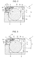
- the operator in a case of setting the heat sensitive paper 15 between the thermal head 6 and the platen roller 7, the operator operates the lever member 14 mounted to the cover member 3 to swing open the cover member 3 as shown in FIG. 3 , and stores the roll-shaped heat sensitive paper 15 in the storing portion 2c provided to the case main body 2.
- the lever member 14 in a case of applying an external force with respect to the lever member 14, the lever member 14 is caused to swing with respect to the cover member 3, and the coil springs 9 are compressed by a small force to cause the slider 8 to move in the inward direction of the swing radius direction of the cover member 3 due to the principle of leverage. Accordingly, the platen roller 7 mounted to the slider 8 is caused to be spaced apart from the thermal head 6, and the engagement state of the engagement pieces 12 fixed to the slider 8 and the engagement concave portions 13 provided to the case main body 2 is released, so the cover member 3 is capable of swinging with respect to the case main body 2.
- the platen roller 7 mounted to the swing end of the cover member 3 is caused to move in a direction in which the platen roller 7 comes to be spaced apart from the thermal head 6, so the storing portion 2c mounted to the case main body 2 is caused to be exposed.
- the operator can readily set the roll-shaped heat sensitive paper 15 in the exposed storing portion 2c, that is, can readily and rapidly execute a recovering operation of a paper jam or a supplying operation of the heat sensitive paper 15.
- the platen roller 7 pressurizes the heat sensitive paper 15 in the outward direction of the swing radius direction on the plane including the rotational center C1 of the platen roller 7 and the swing center C2 of the cover member 3, so a moment for causing the cover member 3 to swing due to the pressurizing force is not generated. Accordingly, the entire biasing force F due to the coil springs 9 can be effectively used to pressurize the heat sensitive paper 15 against the printing surface 6a of the thermal head 6.
- the thermal head 6 is fixed to the side wall 2b of the case main body 2, so only the side wall 2b of the case main body 2 is disposed to a back surface side of the thermal head 6.
- a space in the back surface side of the thermal head 6 can be made smaller, and a width dimension thereof can be reduced, which are advantageous.
- rigidity of the thermal head 6 can be reinforced. As a result, the rigidity of the thermal head 6 itself is not necessarily large, and the thermal head 6 can be made thinner.
- the thermal head 6 is stiffly supported from its back surface by the side wall 2b of the case main body 2, so the biasing force F due to the coil springs 9 can be directly used without being released as the pressurizing force of the thermal head 6 with respect to the heat sensitive paper 15, which is advantageous.
- the storing portion 2c for storing the roll-shaped heat sensitive paper 15 is provided to the inside of the substantially rectangular-parallelepiped box-shaped case 4 including the case main body 2 and the cover member 3 that close the case 4, so dead spaces S are defined in four corners thereof in the outward direction of a radius direction of the heat sensitive paper 15 as shown in FIG. 2 .
- the thermal head 6 is fixed to an upper portion of the side wall 2b of the case main body 2, so the thermal head 6, the platen roller 7, the slider 8, the coil springs 9, and the like can be disposed so as to be stored in the dead spaces S.
- the thermal printer 1 can be structured to be more compact.
- the coil springs 9 are exemplified as biasing means. However, it is not limited thereto, and an arbitrary elastic member may be employed alternatively. Further, the engagement pieces 12 and the engagement concave portions 13 engaged therewith are provided to the slider 8 and the case main body 2, respectively, or may be provided to the case main body 2 and the slider 8, respectively,
- case main body 2 is structured to have a rectangular-parallelepiped box shape
- case main body 2 is not necessarily a rectangular parallelepiped, and any shape capable of storing the roll-shaped heat sensitive paper 15 can be employed.
Landscapes
- Electronic Switches (AREA)
Claims (5)
- Wärmedrucker, umfassend
einen Gehäusehauptkörper (2);
einen Thermokopf (6), der an einer Seitenwand des Gehäusehauptkörpers befestigt ist;
eine Schreibwalze (7), die so angeordnet ist, dass sie einer Druckfläche des Thermokopfs gegenüber liegt, zum Zuführen von wärmeempfindlichem Papier (15) zwischen der Schreibwalze und dem Thermokopf;
ein Vorspannmittel (9) zum Vorspannen der Schreibwalze zu einer Seite des Thermokopfs;
einen Schwenkarm (3), der schwenkbar an dem Gehäusehauptkörper montiert ist; und
gekennzeichnet durch
ein Gleitelement (8), das an einem vorderen Ende des Schwenkarms so montiert ist, dass es imstande ist, sich auf einer Ebene zu bewegen, die einen Drehmittelpunkt (C1) der Schreibwalze und einen Schwenkmittelpunkt (C2) des Schwenkarms enthält, zum Stützen der Schreibwalze in ihrer Drehung,
wobei das Vorspannmittel das Gleitelement und die Schreibwalze (7) entlang der Ebene in einer Richtung weg von dem Schwenkmittelpunkt (C2) des Schwenkarms (3) und zu dem Thermokopf (6) hin vorspannt. - Wärmedrucker nach Anspruch 1, umfassend:ein Eingriffsstück (12), das an dem Gleitelement (8) befestigt ist; undein Eingriffselement (13), das an dem Gehäusehauptkörper vorgesehen ist, das das Eingriffsstück an einer Position in Eingriff bringt, wo die Schreibwalze (7) einer Druckfläche des Thermokopfs (6) gegenüber liegt, um mit dem Schwenkarm (3) in Eingriff zu gelangen.
- Wärmedrucker nach Anspruch 1 oder 2, wobei der Schwenkarm (3) mit einem Hebel (14) versehen ist, der das Gleitelement (8) in eine Richtung zu dem Schwenkmittelpunkt (C2) gegen eine Spannkraft des Vorspannmittels (9) in Bewegung versetzt.
- Wärmedrucker nach einem der vorangehenden Ansprüche, wobei:der Gehäusehauptkörper (2) so konstruiert ist, dass er eine rechteckige, parallelepipedische Kastenform aufweist und mit einem Lagerungsabschnitt (2c) zum Lagern eines rollenförmigen wärmeempfindlichen Papiers (15) versehen ist; undder Thermokopf (6) an einer Seitenwand in einem oberen Abschnitt des Lagerungsabschnitts befestigt ist.
- Wärmedrucker nach Anspruch 4, wobei der Schwenkarm (3) mit einer oberen Abschnittsabdeckung des Lagerungsabschnitts (2c) konstruiert ist.
Applications Claiming Priority (1)
| Application Number | Priority Date | Filing Date | Title |
|---|---|---|---|
| JP2006282983A JP2008100381A (ja) | 2006-10-17 | 2006-10-17 | サーマルプリンタ |
Publications (3)
| Publication Number | Publication Date |
|---|---|
| EP1914082A2 EP1914082A2 (de) | 2008-04-23 |
| EP1914082A3 EP1914082A3 (de) | 2008-12-17 |
| EP1914082B1 true EP1914082B1 (de) | 2011-03-23 |
Family
ID=38834982
Family Applications (1)
| Application Number | Title | Priority Date | Filing Date |
|---|---|---|---|
| EP07254061A Not-in-force EP1914082B1 (de) | 2006-10-17 | 2007-10-12 | Wärmedrucker |
Country Status (5)
| Country | Link |
|---|---|
| US (1) | US7929005B2 (de) |
| EP (1) | EP1914082B1 (de) |
| JP (1) | JP2008100381A (de) |
| KR (1) | KR20080034806A (de) |
| DE (1) | DE602007013338D1 (de) |
Families Citing this family (10)
| Publication number | Priority date | Publication date | Assignee | Title |
|---|---|---|---|---|
| CN101434151B (zh) * | 2007-11-13 | 2010-10-13 | 旭丽电子(广州)有限公司 | 热升华打印机 |
| JP2011168029A (ja) * | 2010-02-22 | 2011-09-01 | Seiko Instruments Inc | プリンタ |
| JP5757768B2 (ja) * | 2011-04-04 | 2015-07-29 | 富士通コンポーネント株式会社 | プリンタ |
| CN106079903B (zh) * | 2016-08-15 | 2017-11-21 | 厦门普瑞特科技有限公司 | 一种快捷装拆的打印机芯 |
| JP6185641B2 (ja) * | 2016-09-29 | 2017-08-23 | サトーホールディングス株式会社 | プリンターのカバーロック機構 |
| JP6834901B2 (ja) * | 2017-10-20 | 2021-02-24 | ブラザー工業株式会社 | 熱転写プリンタ |
| JP6863316B2 (ja) * | 2018-02-28 | 2021-04-21 | ブラザー工業株式会社 | 印刷装置 |
| KR102215011B1 (ko) | 2019-09-09 | 2021-02-10 | 이동연 | 감열프린팅방식 화환리본 라벨띠 제작용 서멀프린터 |
| KR102215012B1 (ko) | 2020-06-29 | 2021-02-10 | 이동연 | 감열프린팅방식 화환리본 라벨띠 제작용 서멀프린터 |
| CN113602639B (zh) * | 2021-07-22 | 2022-09-30 | 河南科技大学第一附属医院 | 一种心内科用热敏纸储存装置 |
Family Cites Families (18)
| Publication number | Priority date | Publication date | Assignee | Title |
|---|---|---|---|---|
| JP2585769B2 (ja) * | 1988-12-14 | 1997-02-26 | 株式会社テック | ラインサーマルプリンタ |
| JPH088823Y2 (ja) * | 1989-04-07 | 1996-03-13 | 株式会社テック | サーマルプリンタ |
| EP0386919A3 (de) * | 1989-03-06 | 1991-01-30 | Tokyo Electric Co., Ltd. | Wärmedrucker |
| US5447380A (en) * | 1992-06-01 | 1995-09-05 | Nai Technologies, Inc. | Thermal printer |
| FR2697776B1 (fr) * | 1992-11-06 | 1995-03-03 | Axiohm | Dispositif d'impression thermique ouvrant. |
| JP3116157B2 (ja) * | 1993-12-27 | 2000-12-11 | セイコーインスツルメンツ株式会社 | ラインプリンタ |
| JPH07256978A (ja) * | 1994-03-25 | 1995-10-09 | Sato:Kk | サーマルプリンタ |
| JP3370517B2 (ja) * | 1996-06-14 | 2003-01-27 | ペンタックス株式会社 | サーマルラインプリンタの構造 |
| JP2852905B2 (ja) * | 1996-09-19 | 1999-02-03 | ローム株式会社 | プリンタ装置 |
| JPH10147023A (ja) * | 1996-09-19 | 1998-06-02 | Seiko Epson Corp | サーマルプリンタ |
| JP4045029B2 (ja) * | 1997-10-09 | 2008-02-13 | セイコーエプソン株式会社 | プリンタ |
| JPH11129571A (ja) * | 1997-10-28 | 1999-05-18 | Seiko Epson Corp | プリンタ |
| JP2000326530A (ja) * | 1999-05-20 | 2000-11-28 | Seiko Epson Corp | サーマルプリンタ |
| JP2003200625A (ja) * | 2001-10-23 | 2003-07-15 | Fujitsu Component Ltd | サーマルプリンタ |
| JP3823918B2 (ja) * | 2002-12-20 | 2006-09-20 | ブラザー工業株式会社 | テープ印字装置 |
| JP4068502B2 (ja) * | 2003-05-23 | 2008-03-26 | セイコーインスツル株式会社 | サーマルプリンタ |
| JP4273110B2 (ja) * | 2005-09-14 | 2009-06-03 | Necインフロンティア株式会社 | フレームオープン機構およびサーマルプリンタ |
| JP4914619B2 (ja) * | 2006-02-23 | 2012-04-11 | セイコーインスツル株式会社 | ヘッド支持構造体、印字装置、熱活性化装置、およびプリンタ |
-
2006
- 2006-10-17 JP JP2006282983A patent/JP2008100381A/ja not_active Withdrawn
-
2007
- 2007-10-04 US US11/906,843 patent/US7929005B2/en not_active Expired - Fee Related
- 2007-10-12 DE DE602007013338T patent/DE602007013338D1/de active Active
- 2007-10-12 EP EP07254061A patent/EP1914082B1/de not_active Not-in-force
- 2007-10-17 KR KR1020070104411A patent/KR20080034806A/ko not_active Ceased
Also Published As
| Publication number | Publication date |
|---|---|
| DE602007013338D1 (de) | 2011-05-05 |
| US20080088692A1 (en) | 2008-04-17 |
| JP2008100381A (ja) | 2008-05-01 |
| US7929005B2 (en) | 2011-04-19 |
| EP1914082A3 (de) | 2008-12-17 |
| EP1914082A2 (de) | 2008-04-23 |
| KR20080034806A (ko) | 2008-04-22 |
Similar Documents
| Publication | Publication Date | Title |
|---|---|---|
| EP1914082B1 (de) | Wärmedrucker | |
| JP4761465B2 (ja) | サーマルプリンタ | |
| US20020024578A1 (en) | Printer installable in small space | |
| US7704001B2 (en) | Image forming apparatus | |
| CN101544129B (zh) | 行式热敏打印机 | |
| US20080135674A1 (en) | Rolled sheet support mechanism and printer | |
| JP7095369B2 (ja) | 印刷装置 | |
| JP6841685B2 (ja) | カバー開閉機構およびプリンタ | |
| JP6351502B2 (ja) | 印字ユニット及びサーマルプリンタ | |
| JP4273110B2 (ja) | フレームオープン機構およびサーマルプリンタ | |
| JPH06122247A (ja) | プリンタ | |
| KR19990014280A (ko) | 프린터 장치 | |
| US20060230956A1 (en) | Cutter apparatus and printer provided with cutter apparatus | |
| CN109328141B (zh) | 打印机 | |
| JP4117498B2 (ja) | プリンタ | |
| JP2013166265A (ja) | サーマルプリンタ | |
| JP4595774B2 (ja) | テープ印字装置 | |
| JP3617146B2 (ja) | 印刷装置 | |
| JP6422333B2 (ja) | 印字ユニット及びプリンタ | |
| JP4347866B2 (ja) | サーマルプリンタ | |
| JP4588673B2 (ja) | プリンタ | |
| JPH0224180A (ja) | プリンタヘッドの圧着装置 | |
| JP2007223158A (ja) | ヘッド支持構造体、印字装置、熱活性化装置、およびプリンタ | |
| JP5702215B2 (ja) | プラテンローラ固定構造及びプリンタ | |
| JP6443286B2 (ja) | 電子機器 |
Legal Events
| Date | Code | Title | Description |
|---|---|---|---|
| PUAI | Public reference made under article 153(3) epc to a published international application that has entered the european phase |
Free format text: ORIGINAL CODE: 0009012 |
|
| AK | Designated contracting states |
Kind code of ref document: A2 Designated state(s): AT BE BG CH CY CZ DE DK EE ES FI FR GB GR HU IE IS IT LI LT LU LV MC MT NL PL PT RO SE SI SK TR |
|
| AX | Request for extension of the european patent |
Extension state: AL BA HR MK RS |
|
| PUAL | Search report despatched |
Free format text: ORIGINAL CODE: 0009013 |
|
| AK | Designated contracting states |
Kind code of ref document: A3 Designated state(s): AT BE BG CH CY CZ DE DK EE ES FI FR GB GR HU IE IS IT LI LT LU LV MC MT NL PL PT RO SE SI SK TR |
|
| AX | Request for extension of the european patent |
Extension state: AL BA HR MK RS |
|
| 17P | Request for examination filed |
Effective date: 20090617 |
|
| AKX | Designation fees paid |
Designated state(s): DE FR GB IT |
|
| 17Q | First examination report despatched |
Effective date: 20090925 |
|
| GRAP | Despatch of communication of intention to grant a patent |
Free format text: ORIGINAL CODE: EPIDOSNIGR1 |
|
| GRAS | Grant fee paid |
Free format text: ORIGINAL CODE: EPIDOSNIGR3 |
|
| GRAA | (expected) grant |
Free format text: ORIGINAL CODE: 0009210 |
|
| AK | Designated contracting states |
Kind code of ref document: B1 Designated state(s): DE FR GB IT |
|
| REG | Reference to a national code |
Ref country code: GB Ref legal event code: FG4D |
|
| REF | Corresponds to: |
Ref document number: 602007013338 Country of ref document: DE Date of ref document: 20110505 Kind code of ref document: P |
|
| REG | Reference to a national code |
Ref country code: DE Ref legal event code: R096 Ref document number: 602007013338 Country of ref document: DE Effective date: 20110505 |
|
| PLBE | No opposition filed within time limit |
Free format text: ORIGINAL CODE: 0009261 |
|
| STAA | Information on the status of an ep patent application or granted ep patent |
Free format text: STATUS: NO OPPOSITION FILED WITHIN TIME LIMIT |
|
| 26N | No opposition filed |
Effective date: 20111227 |
|
| REG | Reference to a national code |
Ref country code: DE Ref legal event code: R097 Ref document number: 602007013338 Country of ref document: DE Effective date: 20111227 |
|
| REG | Reference to a national code |
Ref country code: FR Ref legal event code: PLFP Year of fee payment: 10 |
|
| PGFP | Annual fee paid to national office [announced via postgrant information from national office to epo] |
Ref country code: FR Payment date: 20160919 Year of fee payment: 10 |
|
| PGFP | Annual fee paid to national office [announced via postgrant information from national office to epo] |
Ref country code: GB Payment date: 20161012 Year of fee payment: 10 Ref country code: DE Payment date: 20161004 Year of fee payment: 10 |
|
| PGFP | Annual fee paid to national office [announced via postgrant information from national office to epo] |
Ref country code: IT Payment date: 20161024 Year of fee payment: 10 |
|
| REG | Reference to a national code |
Ref country code: DE Ref legal event code: R119 Ref document number: 602007013338 Country of ref document: DE |
|
| GBPC | Gb: european patent ceased through non-payment of renewal fee |
Effective date: 20171012 |
|
| REG | Reference to a national code |
Ref country code: FR Ref legal event code: ST Effective date: 20180629 |
|
| PG25 | Lapsed in a contracting state [announced via postgrant information from national office to epo] |
Ref country code: DE Free format text: LAPSE BECAUSE OF NON-PAYMENT OF DUE FEES Effective date: 20180501 Ref country code: GB Free format text: LAPSE BECAUSE OF NON-PAYMENT OF DUE FEES Effective date: 20171012 |
|
| PG25 | Lapsed in a contracting state [announced via postgrant information from national office to epo] |
Ref country code: FR Free format text: LAPSE BECAUSE OF NON-PAYMENT OF DUE FEES Effective date: 20171031 |
|
| PG25 | Lapsed in a contracting state [announced via postgrant information from national office to epo] |
Ref country code: IT Free format text: LAPSE BECAUSE OF NON-PAYMENT OF DUE FEES Effective date: 20171012 |