EP1914375A1 - Joint d'angle - Google Patents
Joint d'angle Download PDFInfo
- Publication number
- EP1914375A1 EP1914375A1 EP07118306A EP07118306A EP1914375A1 EP 1914375 A1 EP1914375 A1 EP 1914375A1 EP 07118306 A EP07118306 A EP 07118306A EP 07118306 A EP07118306 A EP 07118306A EP 1914375 A1 EP1914375 A1 EP 1914375A1
- Authority
- EP
- European Patent Office
- Prior art keywords
- section
- arm
- bracket according
- aligning bracket
- seat
- Prior art date
- Legal status (The legal status is an assumption and is not a legal conclusion. Google has not performed a legal analysis and makes no representation as to the accuracy of the status listed.)
- Granted
Links
Images


Classifications
-
- A—HUMAN NECESSITIES
- A47—FURNITURE; DOMESTIC ARTICLES OR APPLIANCES; COFFEE MILLS; SPICE MILLS; SUCTION CLEANERS IN GENERAL
- A47G—HOUSEHOLD OR TABLE EQUIPMENT
- A47G1/00—Mirrors; Picture frames or the like, e.g. provided with heating, lighting or ventilating means
- A47G1/06—Picture frames
- A47G1/10—Corner clips or corner-connecting appliances for frames
- A47G1/101—Corner clips or corner-connecting appliances for frames for insertion within frame members
- A47G1/102—Corner clips or corner-connecting appliances for frames for insertion within frame members having an aperture to receive a fastener to connect to a frame member
-
- E—FIXED CONSTRUCTIONS
- E06—DOORS, WINDOWS, SHUTTERS, OR ROLLER BLINDS IN GENERAL; LADDERS
- E06B—FIXED OR MOVABLE CLOSURES FOR OPENINGS IN BUILDINGS, VEHICLES, FENCES OR LIKE ENCLOSURES IN GENERAL, e.g. DOORS, WINDOWS, BLINDS, GATES
- E06B1/00—Border constructions of openings in walls, floors, or ceilings; Frames to be rigidly mounted in such openings
- E06B1/04—Frames for doors, windows, or the like to be fixed in openings
- E06B1/36—Frames uniquely adapted for windows
- E06B1/38—Frames uniquely adapted for windows for shop, show, or like large windows
-
- E—FIXED CONSTRUCTIONS
- E06—DOORS, WINDOWS, SHUTTERS, OR ROLLER BLINDS IN GENERAL; LADDERS
- E06B—FIXED OR MOVABLE CLOSURES FOR OPENINGS IN BUILDINGS, VEHICLES, FENCES OR LIKE ENCLOSURES IN GENERAL, e.g. DOORS, WINDOWS, BLINDS, GATES
- E06B3/00—Window sashes, door leaves, or like elements for closing wall or like openings; Layout of fixed or moving closures, e.g. windows in wall or like openings; Features of rigidly-mounted outer frames relating to the mounting of wing frames
- E06B3/96—Corner joints or edge joints for windows, doors, or the like frames or wings
- E06B3/964—Corner joints or edge joints for windows, doors, or the like frames or wings using separate connection pieces, e.g. T-connection pieces
- E06B3/968—Corner joints or edge joints for windows, doors, or the like frames or wings using separate connection pieces, e.g. T-connection pieces characterised by the way the connecting pieces are fixed in or on the frame members
- E06B3/9687—Corner joints or edge joints for windows, doors, or the like frames or wings using separate connection pieces, e.g. T-connection pieces characterised by the way the connecting pieces are fixed in or on the frame members with screws blocking the connecting piece inside or on the frame member
- E06B3/9688—Mitre joints
Definitions
- the present invention relates to an aligning bracket for joining together sections.
- the aligning bracket in question is advantageously intended to be used in the sector for the production of frames, such as door and window fixtures, in order to connect together the sections.
- the invention falls generally within the industrial sector relating to the production of frames and in particular the sector relating to the production of accessories for fixtures.
- a frame whether it be made of metal or PVC, generally consists of several sections which are fixed together in pairs at the ends in the region of the vertices by means of suitable connection means.
- the latter consist of generally L-shaped angular parts which are made of metal or plastic and are usually known by the name of "tightening brackets" or “force-fitting brackets”.
- these angular parts have two arms which are perpendicular to each other, each being able to be slidably inserted inside a seat formed longitudinally in one of the two sections to be joined together.
- Suitable fixing means such as screws or bolts for example, are used to fix the arms of the angular parts to the two sections.
- Each angle piece exerts, by means of its arms, a pulling force on the sections to be joined together so as to bring them into contact against each other along the joining cross-section.
- the angular parts therefore allow the various sections to be assembled together next to each other so as to form the frame, ensuring that the adjacent surfaces thereof have a continuous form and are coplanar with each other.
- the angular parts do not always manage to prevent the sections from splaying along their joining zone. This is due mainly to the fact that the sections used to form the thermal break frames have a cross-section which is greater than that of the sections used for "cold section” fixtures and require the use of other mechanical parts to supplement the pulling force of the tightening brackets.
- the sections for thermal break fixtures are formed by a main portion, which forms the load-bearing part of the section and is intended to be directed outwards, and by a secondary portion, which is connected to the main portion by means of a thickness of thermally insulating material and forms the part of the fixture which is intended to be directed inwards.
- the angular connecting parts are mounted for structural reasons in the zone where the main portions of the two sections are joined together and therefore in a position which is offset with respect to the middle axes of the sections.
- the alignment means ensure restoration of the continuity between the surfaces of the sections to be joined together angularly.
- alignment means consist of connecting parts which are substantially similar to the abovementioned angular connecting parts and are usually referred to in the technical sector in question by the name of "aligning brackets".
- the abovementioned aligning brackets are inserted into longitudinal seats where they are fixed using fixing means, such as screws or bolts, or, more recently, by means of locking cam parts which are pivotably mounted on the arms of the brackets.
- cam parts are operationally forced against the edges of the seats of the sections inside which the aligning bracket is inserted.
- each of these cam parts is able to pass from a release position, where it is retracted inside the contour of the arm in order to allow insertion of the latter inside the section, into a locking position, where it is rotated so as to engage with its projecting cam portion against the section so as to pull the latter towards the joining cross-section and fix it in the desired position adjacent to the other section.
- the European patent EP 1048816 describes an embodiment of an aligning bracket provided with cam parts formed by a cylindrical portion inserted inside a special circular seat of the arm and acting as a rotational pin, and a projecting tongue, formed as one piece with the cylindrical portion, from where it extends perpendicularly.
- the tongue is eccentric with respect to the axis of the cylindrical portion so that, following rotation, it is able to pass from the release position, where it is retracted inside the contour of the arm and does not interfere with the section, into the locking position where, projecting from the contour of the arm, it is forced so as to grip against the section.
- the tongue engages with the section, forcing it to slide longitudinally so as to favour movement thereof towards the other section in the joining zone.
- the tongue has an outer edge which is shaped as a circumferential arc and provided with a series of teeth for increasing the grip on the section.
- the aligning bracket described in the patent EP 1048816 has the drawback that the force exerted by the tongues on the sections is transmitted onto the bracket via the pin and therefore onto a plane which is different from that where gripping against the section occurs, resulting in a moment which may cause extraction of the cam part from its seat in the bracket.
- a further drawback of this known bracket consists in the fact that the locking position of the cam is ensured only by the engagement of the teeth provided on the edge of the tongue against the section. Between the pin and the seat where the force transmitted by the tongue is applied there are in fact no fastening means for preventing the cam from moving backwards and releasing the section.
- a further drawback consists in the constructional complexity and in the high costs for production of the brackets designed in accordance with the teaching of the patent EP 1048816 , where the two cam parts on the two arms are produced as two separate asymmetrical components, each of which is formed so as to operate in an associated different direction of rotation.
- the object of the present invention is to eliminate the drawbacks of the known art mentioned above by providing an aligning bracket for joining together sections which ensures more stable engagement.
- Another object of the present invention is to provide an aligning bracket which is operationally entirely failproof and reliable.
- a further object of the present invention is to provide an aligning bracket which is simple and inexpensive to produce.
- bracket 1 denotes the aligning bracket for joining together sections according to the invention.
- This bracket 1 is intended, in particular, for the assembly of frames for thermal break fixtures, but may also be used as a force-fitting bracket during the assembly of frames of any type, form and size and in particular for cold section fixtures, on its own or in addition to other brackets also of the conventional tightening type.
- Each thermal break section is composed of a main portion, intended to form the outer surround of the fixture, and a secondary portion, intended to form the inner surround.
- the two portions are connected together by a further heat-insulating portion.
- the aligning bracket 1 according to the invention is mounted, in the non-limiting example of a thermal break frame, in the zone where the secondary portions of a first and second section I and II are joined together with the aim of moving together the two sections and keeping them in a coplanar relationship.
- the actual structural connection between the two sections I and II is performed in the region of their main portions by means of an ordinary force-fitting bracket (not shown).
- the aligning bracket 1 is associated with the two sections I and II at the same time as the abovementioned force-fitting bracket during assembly of the frame.
- Each section I and II is provided with a special longitudinal seat S formed in the abovementioned inner portion.
- Said seat extends longitudinally along the entire length of the section I and II and is bounded by two parallel facing edges, one of which, indicated by B2, is situated closer to the inner edge of the section than the other one indicated by B1.
- the aligning bracket 1 is formed mainly by an angle piece 2 in the form of a flat plate, preferably made of aluminium alloy or, where appropriate, steel, having two mutually perpendicular arms 3a and 3b forming an L-shaped section.
- the two arms are intended to be inserted inside the seats S of the first and second section I and II, respectively. This insertion is performed with the sections separated, by means a direct translatory sliding movement longitudinally with respect to the individual section I, II.
- each arm 3a and 3b of the angle piece 2 is provided with suitable means for performing locking with the section I, II, said means being able to lock in position the arm 3a, 3b itself inside the longitudinal seat S and at the same time impart to the section I and II an additional sliding movement towards the joining zone.
- the abovementioned means are formed as a locking piece 4 mounted in a seat 5 provided on each arm 3a, 3b and able to move between a release position A, where it does not intercept the section, leaving the arm 3a, 3b free to slide inside the longitudinal seat S, and a locking position B, where it acts against the section I, II, forcing it to be joined to the other section.
- each locking piece 4 performs a rotary/translatory movement between the release position A and the locking position B.
- the locking piece 4 is formed by a head portion 6 and a pin portion 7 which are made as one piece, for example by means of moulding.
- the head portion 4 defines a retaining surface 8 able to grip against the corresponding section I and II and a cam surface 9 able to bear against a sliding surface 10 provided in the seat 5 of the corresponding arm 3a, 3b of the angle piece 2.
- the pin portion 7 is able to slide in a guided manner inside a track 11 provided in the bottom 12 of the seat 5 of the corresponding arm 3a, 3b of the angle piece 2.
- the locking piece 4 moves with a rotary/translatory movement between the release position A and the locking position B, performed by engagement of the cam surface 9 with the sliding surface 10 and by engagement of the pin portion 7 inside the track 11.
- the retaining surface 8 of the head portion 6 is situated inside the contour of the arm 3a, 3b so as to allow the latter to slide freely inside the longitudinal seat S of the corresponding section I, II, and outside of the contour of the arm 3a, 3b so as to grip against the corresponding section I, II.
- the locking piece 4 is preferably mushroom-shaped, with the cap which defines the head portion 6 and the stem which defines the pin portion 7.
- the head portion 6 has a form which is symmetrical with respect to an axis X passing through the points of engagement of its cam surface 9 and retaining surface 8 with the sliding surface 10 and with the section I, II, respectively.
- this symmetrical form is substantially oval with the axis of symmetry corresponding to the larger axis of the oval.
- the retaining surface 8 and the sliding surface 10 of the head portion 6 are divided in mirror-image fashion by the axis of symmetry, allowing the locking piece to have an identical functional capacity in the two directions of rotary/translatory movement corresponding to mounting on the right-hand or left-hand arm of the angle piece 2.
- the pin portion 7 has the shape substantially of a cylinder fixed on the axis of symmetry X below the head portion 6.
- the track 11 has the width of the stem so as to constrain the sliding movement thereof inside it, performed by engagement of the cam surface 9 with the sliding surface 10.
- the locking piece 4 owing to its symmetry, is able to work correctly in both directions of rotation and therefore it may be arranged equally well on the two arms 3a, 3b of the angle piece 2, resulting in a significant ease of assembly of the bracket 1 which does not require, as in solutions of the known type, the provision of different locking pieces each solely able to be associated with one arm of the bracket.
- the locking piece 4 may also have a non-symmetrical form and the sliding surface 10 may also be formed not parallel to the edge of the arm 3a,3b of the angle piece 2, but suitably angled so as to allow the fastening element to achieve an optimum grip inside the section.
- Each seat 5, which is intended to receive the locking piece 4 is formed by means of a depression with the bottom 15 situated about halfway along the thickness of the angle piece 2 and is formed in a first surface 12 of the arm 3a, 3b, extending from at least one of its sides 13, 14.
- the abovementioned depression has the form of a step with the riser perpendicular to the bottom 15 and defining in the inner part the sliding surface 10 with a curved progression, which is therefore perpendicular to the plane defined by the angle piece 2.
- the track 11 is realised in the form of a through-cavity formed in the bottom of the depression.
- the seats 5 may be provided both on the inner side 13 and on the outer side 14 or on both sides as in the case of the examples shown in the accompanying figures.
- the locking pieces 4 will be provided two in number on each arm 3a, 3b and on a same inner side 13 or outer side 14.
- the provision of the seats also on the side where the locking pieces 4 are not mounted has the aim of minimising the production and storage costs owing to the manufacture of a single part.
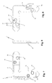
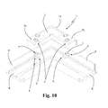
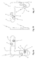
- Figures 1-9 show a first example of an aligning bracket 1 according to the invention with the locking pieces 4 mounted on the inner side 13 of the arms 3a and 3b of the angle piece 2, while Figures 10-18 show a second example of an aligning bracket 1 according to the invention with the locking pieces 4 mounted on the outer side 14 of the arms 3a and 3b of the angle piece 2.
- the locking pieces 4 will be forced towards the locking position B by means of a special spanner acting in a special shaped seat 16 provided above the head portions 6 of the said locking pieces 4.
- the retaining surface 8 of the head portion 6 will project outside the contour of the arm 3a, 3b until it grips against the section I, II as a result of a rotary/translatory movement performed by engagement of the cam surface 9 on the sliding surface 10 and by engagement of the pin portion 7 inside the track 11.
- the profiles of the cam surface 9 and the sliding surface 10 have been designed to determine a pressure which is smaller at the start and greater at the end of the rotary/translatory movement which causes alignment of the sections I and II in an optimum manner.
- the force transmitted by the engagement between the retaining surface and the section I, II is transmitted axially by means of the cam surface 9 onto the sliding surface 10 and not onto the track 11 of the pin portion 7.
- the locking position B is particularly stable owing to the dual engagement between the cam surface 9 and sliding surface 10 and between the retaining surface 8 and the section I, II, onto which the entire force is transmitted.
- the retaining surface 8, cam surface 9 and sliding surface 10 are knurled or provided with teeth able to increase the friction.
- the two arms 3a and 3b may also not be perpendicular to each other so as to allow the use of the bracket 1 according to the invention also in frames for fixtures forming angles which are not right angles.
- the invention thus conceived therefore achieves the predefined objects.
Landscapes
- Engineering & Computer Science (AREA)
- Civil Engineering (AREA)
- Structural Engineering (AREA)
- Connection Of Plates (AREA)
- Prostheses (AREA)
- Percussion Or Vibration Massage (AREA)
- Liquid Crystal (AREA)
- Hinges (AREA)
- Processing Of Terminals (AREA)
- Mechanical Coupling Of Light Guides (AREA)
- Paper (AREA)
Applications Claiming Priority (1)
| Application Number | Priority Date | Filing Date | Title |
|---|---|---|---|
| IT000381A ITPD20060381A1 (it) | 2006-10-12 | 2006-10-12 | Squadra di allineamento |
Publications (2)
| Publication Number | Publication Date |
|---|---|
| EP1914375A1 true EP1914375A1 (fr) | 2008-04-23 |
| EP1914375B1 EP1914375B1 (fr) | 2010-07-07 |
Family
ID=39016295
Family Applications (1)
| Application Number | Title | Priority Date | Filing Date |
|---|---|---|---|
| EP07118306A Active EP1914375B1 (fr) | 2006-10-12 | 2007-10-11 | Joint d'angle |
Country Status (5)
| Country | Link |
|---|---|
| EP (1) | EP1914375B1 (fr) |
| AT (1) | ATE473346T1 (fr) |
| DE (1) | DE602007007557D1 (fr) |
| ES (1) | ES2348560T3 (fr) |
| IT (1) | ITPD20060381A1 (fr) |
Cited By (10)
| Publication number | Priority date | Publication date | Assignee | Title |
|---|---|---|---|---|
| ITMI20081456A1 (it) * | 2008-08-04 | 2010-02-04 | Ragni S R L | Gruppo squadretta e metodo per l'allineamento e la connessione angolare di elementi profilati |
| CN102936990A (zh) * | 2012-11-05 | 2013-02-20 | 无锡市风云铝业有限公司 | 一种连接异形角铝 |
| ITRN20120032A1 (it) * | 2012-06-20 | 2013-12-21 | Alutech Italia Group S R L | Struttura portante componibile per insegne pubblicitarie |
| CN111270958A (zh) * | 2020-03-17 | 2020-06-12 | 北京洛嘉奇科技有限公司 | 一种组装型注胶角码及包括其的门窗 |
| EP3783181A1 (fr) | 2019-08-20 | 2021-02-24 | profine GmbH | Connecteur angulaire pour un pleine coque d'un cadre de support pour un profilé de fenêtre |
| EP3783182A1 (fr) | 2019-08-20 | 2021-02-24 | profine GmbH | Cadre composite pour une fenêtre ou une porte |
| IT202000017839A1 (it) * | 2020-07-23 | 2022-01-23 | Europrofili Group S P A | Sistema di chiusura con dispositivo giunto |
| US20220275679A1 (en) * | 2019-07-31 | 2022-09-01 | Cavity Sliders Limited | An Improved Bracket |
| CN115613941A (zh) * | 2022-10-21 | 2023-01-17 | 四川名人居门窗有限公司 | 一种夹片式组角连接件 |
| CN117798865A (zh) * | 2024-03-01 | 2024-04-02 | 江苏龙腾门业有限公司 | 一种屏蔽门生产装置的连接机构 |
Families Citing this family (2)
| Publication number | Priority date | Publication date | Assignee | Title |
|---|---|---|---|---|
| DE102021116600A1 (de) | 2021-06-28 | 2022-12-29 | Profine Gmbh | Verbundrahmen für ein Fenster oder eine Tür |
| DE102021116601A1 (de) | 2021-06-28 | 2022-12-29 | Profine Gmbh | Mit Anbauteilen verbindbarer Verbundrahmen für ein Fenster oder eine Tür |
Citations (9)
| Publication number | Priority date | Publication date | Assignee | Title |
|---|---|---|---|---|
| DE1252399B (de) * | 1967-10-19 | Metaux Legers &. Metaux Non-Ferreux SA, Brüssel | Eckverbindung von Rahmenprofilen fur Fensterflügelrahmen und feststehende Fensterrahmen, die im Querschnitt einen geschlossenen oder offenen Hohlraum aufweisen | |
| DE2656958A1 (de) | 1976-12-16 | 1978-06-22 | Uhl Geb Gmbh & Co Kg | Eckverbindung von auf gehrung geschnittenen profilen |
| US4122617A (en) * | 1974-08-12 | 1978-10-31 | Helmar Nielsen | Picture frame |
| US4538936A (en) | 1983-12-08 | 1985-09-03 | Trw Automotive Products, Inc. | Frame corner |
| US4547986A (en) | 1982-12-27 | 1985-10-22 | Nielsen Moulding Design Corp. | Framing system |
| DE4309274A1 (de) | 1993-03-23 | 1994-09-29 | Huels Troisdorf | Eckverbinder für Verkleidungsstücke und mehrteilige Verkleidung von Fenster- oder Türprofilen o. dgl. und Verfahren zu ihrer Herstellung |
| EP1048816A1 (fr) | 1999-04-30 | 2000-11-02 | L.M. dei F.lli Monticelli S.r.l. | Dispositif et méthode pour raccorder des éléments profilés dans la fabrication des cadres plans |
| DE202005006847U1 (de) * | 2005-04-27 | 2005-07-28 | Hirsch, Bodo | Eckverbindung für Fenster |
| EP1688578A2 (fr) * | 2005-01-21 | 2006-08-09 | Fratelli Comunello S.p.A. | Etrier d'alignement pour fixations |
-
2006
- 2006-10-12 IT IT000381A patent/ITPD20060381A1/it unknown
-
2007
- 2007-10-11 DE DE602007007557T patent/DE602007007557D1/de active Active
- 2007-10-11 ES ES07118306T patent/ES2348560T3/es active Active
- 2007-10-11 EP EP07118306A patent/EP1914375B1/fr active Active
- 2007-10-11 AT AT07118306T patent/ATE473346T1/de not_active IP Right Cessation
Patent Citations (9)
| Publication number | Priority date | Publication date | Assignee | Title |
|---|---|---|---|---|
| DE1252399B (de) * | 1967-10-19 | Metaux Legers &. Metaux Non-Ferreux SA, Brüssel | Eckverbindung von Rahmenprofilen fur Fensterflügelrahmen und feststehende Fensterrahmen, die im Querschnitt einen geschlossenen oder offenen Hohlraum aufweisen | |
| US4122617A (en) * | 1974-08-12 | 1978-10-31 | Helmar Nielsen | Picture frame |
| DE2656958A1 (de) | 1976-12-16 | 1978-06-22 | Uhl Geb Gmbh & Co Kg | Eckverbindung von auf gehrung geschnittenen profilen |
| US4547986A (en) | 1982-12-27 | 1985-10-22 | Nielsen Moulding Design Corp. | Framing system |
| US4538936A (en) | 1983-12-08 | 1985-09-03 | Trw Automotive Products, Inc. | Frame corner |
| DE4309274A1 (de) | 1993-03-23 | 1994-09-29 | Huels Troisdorf | Eckverbinder für Verkleidungsstücke und mehrteilige Verkleidung von Fenster- oder Türprofilen o. dgl. und Verfahren zu ihrer Herstellung |
| EP1048816A1 (fr) | 1999-04-30 | 2000-11-02 | L.M. dei F.lli Monticelli S.r.l. | Dispositif et méthode pour raccorder des éléments profilés dans la fabrication des cadres plans |
| EP1688578A2 (fr) * | 2005-01-21 | 2006-08-09 | Fratelli Comunello S.p.A. | Etrier d'alignement pour fixations |
| DE202005006847U1 (de) * | 2005-04-27 | 2005-07-28 | Hirsch, Bodo | Eckverbindung für Fenster |
Cited By (13)
| Publication number | Priority date | Publication date | Assignee | Title |
|---|---|---|---|---|
| ITMI20081456A1 (it) * | 2008-08-04 | 2010-02-04 | Ragni S R L | Gruppo squadretta e metodo per l'allineamento e la connessione angolare di elementi profilati |
| ITRN20120032A1 (it) * | 2012-06-20 | 2013-12-21 | Alutech Italia Group S R L | Struttura portante componibile per insegne pubblicitarie |
| CN102936990A (zh) * | 2012-11-05 | 2013-02-20 | 无锡市风云铝业有限公司 | 一种连接异形角铝 |
| US11952834B2 (en) * | 2019-07-31 | 2024-04-09 | Cavity Sliders Limited | Bracket |
| US20220275679A1 (en) * | 2019-07-31 | 2022-09-01 | Cavity Sliders Limited | An Improved Bracket |
| EP3783181A1 (fr) | 2019-08-20 | 2021-02-24 | profine GmbH | Connecteur angulaire pour un pleine coque d'un cadre de support pour un profilé de fenêtre |
| EP3783182A1 (fr) | 2019-08-20 | 2021-02-24 | profine GmbH | Cadre composite pour une fenêtre ou une porte |
| CN111270958A (zh) * | 2020-03-17 | 2020-06-12 | 北京洛嘉奇科技有限公司 | 一种组装型注胶角码及包括其的门窗 |
| CN111270958B (zh) * | 2020-03-17 | 2024-04-09 | 山东泓铸智能科技有限公司 | 一种组装型注胶角码及包括其的门窗 |
| IT202000017839A1 (it) * | 2020-07-23 | 2022-01-23 | Europrofili Group S P A | Sistema di chiusura con dispositivo giunto |
| CN115613941A (zh) * | 2022-10-21 | 2023-01-17 | 四川名人居门窗有限公司 | 一种夹片式组角连接件 |
| CN117798865A (zh) * | 2024-03-01 | 2024-04-02 | 江苏龙腾门业有限公司 | 一种屏蔽门生产装置的连接机构 |
| CN117798865B (zh) * | 2024-03-01 | 2024-05-07 | 江苏龙腾门业有限公司 | 一种屏蔽门生产装置的连接机构 |
Also Published As
| Publication number | Publication date |
|---|---|
| ATE473346T1 (de) | 2010-07-15 |
| ITPD20060381A1 (it) | 2008-04-13 |
| ES2348560T3 (es) | 2010-12-09 |
| EP1914375B1 (fr) | 2010-07-07 |
| DE602007007557D1 (de) | 2010-08-19 |
Similar Documents
| Publication | Publication Date | Title |
|---|---|---|
| EP1914375B1 (fr) | Joint d'angle | |
| EP1430225B1 (fr) | Dispositif et procede pour raccorder de maniere amovible des parties structurelles en butee et un element de liaison pour former ledit dispositif | |
| CA2427096A1 (fr) | Chevillage integre pour le montage de meubles | |
| US5655346A (en) | Structural mounting system | |
| US5244324A (en) | Anchoring retainer for threaded fastener | |
| US9673752B2 (en) | Photovoltaic array skirt and mounting hardware | |
| JP2002531794A (ja) | 2本の成形ロッドのt結合 | |
| US20140259526A1 (en) | Quick coupling furniture hinge | |
| CN109844328A (zh) | 将保持元件固定在承载件上的紧固件和包括这种紧固件和保持元件的系统 | |
| TW200424417A (en) | Slide hinge | |
| US6863464B1 (en) | Detachable assembly of two elements | |
| ITMI20110841A1 (it) | Accoppiamento rimuovibile fra un manico e una padella e padella con tale accoppiamento | |
| JP2001501137A (ja) | ハンドツールのロック装置 | |
| US20060255225A1 (en) | Clamp for connecting two elements arranged at an angle to each other, in a support structure | |
| US10077891B2 (en) | Luminaire connection systems | |
| US759608A (en) | Clamp for holding plate-glass. | |
| EP2363035B1 (fr) | Butée inférieure pour fermeture à glissière | |
| US4742658A (en) | Frame structure | |
| EP1688578B1 (fr) | Etrier d'alignement pour fixations | |
| US4402116A (en) | Concealed interlocking fastener | |
| EP2942451B1 (fr) | Système de fixation de profilés | |
| EP0969177A1 (fr) | Elément de raccord pour un profilé composite ainsi qu'un profilé composite pourvu d'un tel raccord | |
| KR102694452B1 (ko) | 프로파일용 연결구조체 | |
| JP2007092515A (ja) | 管継手 | |
| EP0943775B1 (fr) | Assemblage d'éléments structuraux, notamment un profilé et un élément isolant thermiquement |
Legal Events
| Date | Code | Title | Description |
|---|---|---|---|
| PUAI | Public reference made under article 153(3) epc to a published international application that has entered the european phase |
Free format text: ORIGINAL CODE: 0009012 |
|
| AK | Designated contracting states |
Kind code of ref document: A1 Designated state(s): AT BE BG CH CY CZ DE DK EE ES FI FR GB GR HU IE IS IT LI LT LU LV MC MT NL PL PT RO SE SI SK TR |
|
| AX | Request for extension of the european patent |
Extension state: AL BA HR MK RS |
|
| 17P | Request for examination filed |
Effective date: 20080415 |
|
| AKX | Designation fees paid |
Designated state(s): AT BE BG CH CY CZ DE DK EE ES FI FR GB GR HU IE IS IT LI LT LU LV MC MT NL PL PT RO SE SI SK TR |
|
| GRAP | Despatch of communication of intention to grant a patent |
Free format text: ORIGINAL CODE: EPIDOSNIGR1 |
|
| GRAS | Grant fee paid |
Free format text: ORIGINAL CODE: EPIDOSNIGR3 |
|
| GRAA | (expected) grant |
Free format text: ORIGINAL CODE: 0009210 |
|
| AK | Designated contracting states |
Kind code of ref document: B1 Designated state(s): AT BE BG CH CY CZ DE DK EE ES FI FR GB GR HU IE IS IT LI LT LU LV MC MT NL PL PT RO SE SI SK TR |
|
| REG | Reference to a national code |
Ref country code: GB Ref legal event code: FG4D |
|
| REG | Reference to a national code |
Ref country code: CH Ref legal event code: EP |
|
| REG | Reference to a national code |
Ref country code: IE Ref legal event code: FG4D |
|
| REF | Corresponds to: |
Ref document number: 602007007557 Country of ref document: DE Date of ref document: 20100819 Kind code of ref document: P |
|
| REG | Reference to a national code |
Ref country code: NL Ref legal event code: VDEP Effective date: 20100707 |
|
| REG | Reference to a national code |
Ref country code: ES Ref legal event code: FG2A Effective date: 20101125 |
|
| PG25 | Lapsed in a contracting state [announced via postgrant information from national office to epo] |
Ref country code: SI Free format text: LAPSE BECAUSE OF FAILURE TO SUBMIT A TRANSLATION OF THE DESCRIPTION OR TO PAY THE FEE WITHIN THE PRESCRIBED TIME-LIMIT Effective date: 20100707 |
|
| LTIE | Lt: invalidation of european patent or patent extension |
Effective date: 20100707 |
|
| PG25 | Lapsed in a contracting state [announced via postgrant information from national office to epo] |
Ref country code: FI Free format text: LAPSE BECAUSE OF FAILURE TO SUBMIT A TRANSLATION OF THE DESCRIPTION OR TO PAY THE FEE WITHIN THE PRESCRIBED TIME-LIMIT Effective date: 20100707 Ref country code: NL Free format text: LAPSE BECAUSE OF FAILURE TO SUBMIT A TRANSLATION OF THE DESCRIPTION OR TO PAY THE FEE WITHIN THE PRESCRIBED TIME-LIMIT Effective date: 20100707 Ref country code: AT Free format text: LAPSE BECAUSE OF FAILURE TO SUBMIT A TRANSLATION OF THE DESCRIPTION OR TO PAY THE FEE WITHIN THE PRESCRIBED TIME-LIMIT Effective date: 20100707 Ref country code: LT Free format text: LAPSE BECAUSE OF FAILURE TO SUBMIT A TRANSLATION OF THE DESCRIPTION OR TO PAY THE FEE WITHIN THE PRESCRIBED TIME-LIMIT Effective date: 20100707 |
|
| PG25 | Lapsed in a contracting state [announced via postgrant information from national office to epo] |
Ref country code: BG Free format text: LAPSE BECAUSE OF FAILURE TO SUBMIT A TRANSLATION OF THE DESCRIPTION OR TO PAY THE FEE WITHIN THE PRESCRIBED TIME-LIMIT Effective date: 20101007 Ref country code: CY Free format text: LAPSE BECAUSE OF FAILURE TO SUBMIT A TRANSLATION OF THE DESCRIPTION OR TO PAY THE FEE WITHIN THE PRESCRIBED TIME-LIMIT Effective date: 20100707 Ref country code: PT Free format text: LAPSE BECAUSE OF FAILURE TO SUBMIT A TRANSLATION OF THE DESCRIPTION OR TO PAY THE FEE WITHIN THE PRESCRIBED TIME-LIMIT Effective date: 20101108 Ref country code: PL Free format text: LAPSE BECAUSE OF FAILURE TO SUBMIT A TRANSLATION OF THE DESCRIPTION OR TO PAY THE FEE WITHIN THE PRESCRIBED TIME-LIMIT Effective date: 20100707 Ref country code: IS Free format text: LAPSE BECAUSE OF FAILURE TO SUBMIT A TRANSLATION OF THE DESCRIPTION OR TO PAY THE FEE WITHIN THE PRESCRIBED TIME-LIMIT Effective date: 20101107 |
|
| PG25 | Lapsed in a contracting state [announced via postgrant information from national office to epo] |
Ref country code: SE Free format text: LAPSE BECAUSE OF FAILURE TO SUBMIT A TRANSLATION OF THE DESCRIPTION OR TO PAY THE FEE WITHIN THE PRESCRIBED TIME-LIMIT Effective date: 20100707 Ref country code: BE Free format text: LAPSE BECAUSE OF FAILURE TO SUBMIT A TRANSLATION OF THE DESCRIPTION OR TO PAY THE FEE WITHIN THE PRESCRIBED TIME-LIMIT Effective date: 20100707 Ref country code: GR Free format text: LAPSE BECAUSE OF FAILURE TO SUBMIT A TRANSLATION OF THE DESCRIPTION OR TO PAY THE FEE WITHIN THE PRESCRIBED TIME-LIMIT Effective date: 20101008 Ref country code: LV Free format text: LAPSE BECAUSE OF FAILURE TO SUBMIT A TRANSLATION OF THE DESCRIPTION OR TO PAY THE FEE WITHIN THE PRESCRIBED TIME-LIMIT Effective date: 20100707 |
|
| PG25 | Lapsed in a contracting state [announced via postgrant information from national office to epo] |
Ref country code: DK Free format text: LAPSE BECAUSE OF FAILURE TO SUBMIT A TRANSLATION OF THE DESCRIPTION OR TO PAY THE FEE WITHIN THE PRESCRIBED TIME-LIMIT Effective date: 20100707 |
|
| PLBE | No opposition filed within time limit |
Free format text: ORIGINAL CODE: 0009261 |
|
| STAA | Information on the status of an ep patent application or granted ep patent |
Free format text: STATUS: NO OPPOSITION FILED WITHIN TIME LIMIT |
|
| PG25 | Lapsed in a contracting state [announced via postgrant information from national office to epo] |
Ref country code: EE Free format text: LAPSE BECAUSE OF FAILURE TO SUBMIT A TRANSLATION OF THE DESCRIPTION OR TO PAY THE FEE WITHIN THE PRESCRIBED TIME-LIMIT Effective date: 20100707 Ref country code: SK Free format text: LAPSE BECAUSE OF FAILURE TO SUBMIT A TRANSLATION OF THE DESCRIPTION OR TO PAY THE FEE WITHIN THE PRESCRIBED TIME-LIMIT Effective date: 20100707 Ref country code: CZ Free format text: LAPSE BECAUSE OF FAILURE TO SUBMIT A TRANSLATION OF THE DESCRIPTION OR TO PAY THE FEE WITHIN THE PRESCRIBED TIME-LIMIT Effective date: 20100707 Ref country code: MC Free format text: LAPSE BECAUSE OF NON-PAYMENT OF DUE FEES Effective date: 20101031 Ref country code: RO Free format text: LAPSE BECAUSE OF FAILURE TO SUBMIT A TRANSLATION OF THE DESCRIPTION OR TO PAY THE FEE WITHIN THE PRESCRIBED TIME-LIMIT Effective date: 20100707 |
|
| 26N | No opposition filed |
Effective date: 20110408 |
|
| REG | Reference to a national code |
Ref country code: DE Ref legal event code: R097 Ref document number: 602007007557 Country of ref document: DE Effective date: 20110408 |
|
| PG25 | Lapsed in a contracting state [announced via postgrant information from national office to epo] |
Ref country code: IE Free format text: LAPSE BECAUSE OF NON-PAYMENT OF DUE FEES Effective date: 20101011 |
|
| PG25 | Lapsed in a contracting state [announced via postgrant information from national office to epo] |
Ref country code: IT Free format text: LAPSE BECAUSE OF NON-PAYMENT OF DUE FEES Effective date: 20101011 Ref country code: MT Free format text: LAPSE BECAUSE OF FAILURE TO SUBMIT A TRANSLATION OF THE DESCRIPTION OR TO PAY THE FEE WITHIN THE PRESCRIBED TIME-LIMIT Effective date: 20100707 |
|
| REG | Reference to a national code |
Ref country code: CH Ref legal event code: PL |
|
| GBPC | Gb: european patent ceased through non-payment of renewal fee |
Effective date: 20111011 |
|
| PG25 | Lapsed in a contracting state [announced via postgrant information from national office to epo] |
Ref country code: LI Free format text: LAPSE BECAUSE OF NON-PAYMENT OF DUE FEES Effective date: 20111031 Ref country code: CH Free format text: LAPSE BECAUSE OF NON-PAYMENT OF DUE FEES Effective date: 20111031 |
|
| PG25 | Lapsed in a contracting state [announced via postgrant information from national office to epo] |
Ref country code: GB Free format text: LAPSE BECAUSE OF NON-PAYMENT OF DUE FEES Effective date: 20111011 |
|
| PG25 | Lapsed in a contracting state [announced via postgrant information from national office to epo] |
Ref country code: HU Free format text: LAPSE BECAUSE OF FAILURE TO SUBMIT A TRANSLATION OF THE DESCRIPTION OR TO PAY THE FEE WITHIN THE PRESCRIBED TIME-LIMIT Effective date: 20110108 Ref country code: LU Free format text: LAPSE BECAUSE OF NON-PAYMENT OF DUE FEES Effective date: 20101011 |
|
| PG25 | Lapsed in a contracting state [announced via postgrant information from national office to epo] |
Ref country code: TR Free format text: LAPSE BECAUSE OF FAILURE TO SUBMIT A TRANSLATION OF THE DESCRIPTION OR TO PAY THE FEE WITHIN THE PRESCRIBED TIME-LIMIT Effective date: 20100707 |
|
| REG | Reference to a national code |
Ref country code: FR Ref legal event code: PLFP Year of fee payment: 9 |
|
| PG25 | Lapsed in a contracting state [announced via postgrant information from national office to epo] |
Ref country code: IT Free format text: LAPSE BECAUSE OF NON-PAYMENT OF DUE FEES Effective date: 20151011 |
|
| REG | Reference to a national code |
Ref country code: FR Ref legal event code: PLFP Year of fee payment: 10 |
|
| PG25 | Lapsed in a contracting state [announced via postgrant information from national office to epo] |
Ref country code: IT Free format text: LAPSE BECAUSE OF NON-PAYMENT OF DUE FEES Effective date: 20151011 |
|
| PGRI | Patent reinstated in contracting state [announced from national office to epo] |
Ref country code: IT Effective date: 20161125 |
|
| REG | Reference to a national code |
Ref country code: FR Ref legal event code: PLFP Year of fee payment: 11 |
|
| REG | Reference to a national code |
Ref country code: FR Ref legal event code: PLFP Year of fee payment: 12 |
|
| P01 | Opt-out of the competence of the unified patent court (upc) registered |
Effective date: 20230306 |
|
| PGFP | Annual fee paid to national office [announced via postgrant information from national office to epo] |
Ref country code: IT Payment date: 20250926 Year of fee payment: 19 |
|
| PGFP | Annual fee paid to national office [announced via postgrant information from national office to epo] |
Ref country code: DE Payment date: 20251021 Year of fee payment: 19 |
|
| PGFP | Annual fee paid to national office [announced via postgrant information from national office to epo] |
Ref country code: FR Payment date: 20251029 Year of fee payment: 19 |
|
| PGFP | Annual fee paid to national office [announced via postgrant information from national office to epo] |
Ref country code: ES Payment date: 20251210 Year of fee payment: 19 |