EP1914708A2 - Appareil d'affichage à plasma - Google Patents
Appareil d'affichage à plasma Download PDFInfo
- Publication number
- EP1914708A2 EP1914708A2 EP07250466A EP07250466A EP1914708A2 EP 1914708 A2 EP1914708 A2 EP 1914708A2 EP 07250466 A EP07250466 A EP 07250466A EP 07250466 A EP07250466 A EP 07250466A EP 1914708 A2 EP1914708 A2 EP 1914708A2
- Authority
- EP
- European Patent Office
- Prior art keywords
- electrode
- sustain
- signal
- voltage
- plasma display
- Prior art date
- Legal status (The legal status is an assumption and is not a legal conclusion. Google has not performed a legal analysis and makes no representation as to the accuracy of the status listed.)
- Ceased
Links
- 239000010410 layer Substances 0.000 description 32
- OAICVXFJPJFONN-UHFFFAOYSA-N Phosphorus Chemical compound [P] OAICVXFJPJFONN-UHFFFAOYSA-N 0.000 description 17
- 230000004888 barrier function Effects 0.000 description 12
- 150000002500 ions Chemical class 0.000 description 11
- 238000010586 diagram Methods 0.000 description 10
- 101150071665 img2 gene Proteins 0.000 description 8
- 230000015556 catabolic process Effects 0.000 description 7
- 230000007423 decrease Effects 0.000 description 7
- 238000006731 degradation reaction Methods 0.000 description 7
- 239000000758 substrate Substances 0.000 description 5
- 238000000034 method Methods 0.000 description 4
- 101150013335 img1 gene Proteins 0.000 description 2
- 239000011241 protective layer Substances 0.000 description 2
- 230000000694 effects Effects 0.000 description 1
- 238000012986 modification Methods 0.000 description 1
- 230000004048 modification Effects 0.000 description 1
- 238000005192 partition Methods 0.000 description 1
Images





Classifications
-
- G—PHYSICS
- G09—EDUCATION; CRYPTOGRAPHY; DISPLAY; ADVERTISING; SEALS
- G09G—ARRANGEMENTS OR CIRCUITS FOR CONTROL OF INDICATING DEVICES USING STATIC MEANS TO PRESENT VARIABLE INFORMATION
- G09G3/00—Control arrangements or circuits, of interest only in connection with visual indicators other than cathode-ray tubes
- G09G3/20—Control arrangements or circuits, of interest only in connection with visual indicators other than cathode-ray tubes for presentation of an assembly of a number of characters, e.g. a page, by composing the assembly by combination of individual elements arranged in a matrix no fixed position being assigned to or needed to be assigned to the individual characters or partial characters
- G09G3/22—Control arrangements or circuits, of interest only in connection with visual indicators other than cathode-ray tubes for presentation of an assembly of a number of characters, e.g. a page, by composing the assembly by combination of individual elements arranged in a matrix no fixed position being assigned to or needed to be assigned to the individual characters or partial characters using controlled light sources
- G09G3/28—Control arrangements or circuits, of interest only in connection with visual indicators other than cathode-ray tubes for presentation of an assembly of a number of characters, e.g. a page, by composing the assembly by combination of individual elements arranged in a matrix no fixed position being assigned to or needed to be assigned to the individual characters or partial characters using controlled light sources using luminous gas-discharge panels, e.g. plasma panels
- G09G3/288—Control arrangements or circuits, of interest only in connection with visual indicators other than cathode-ray tubes for presentation of an assembly of a number of characters, e.g. a page, by composing the assembly by combination of individual elements arranged in a matrix no fixed position being assigned to or needed to be assigned to the individual characters or partial characters using controlled light sources using luminous gas-discharge panels, e.g. plasma panels using AC panels
- G09G3/291—Control arrangements or circuits, of interest only in connection with visual indicators other than cathode-ray tubes for presentation of an assembly of a number of characters, e.g. a page, by composing the assembly by combination of individual elements arranged in a matrix no fixed position being assigned to or needed to be assigned to the individual characters or partial characters using controlled light sources using luminous gas-discharge panels, e.g. plasma panels using AC panels controlling the gas discharge to control a cell condition, e.g. by means of specific pulse shapes
- G09G3/294—Control arrangements or circuits, of interest only in connection with visual indicators other than cathode-ray tubes for presentation of an assembly of a number of characters, e.g. a page, by composing the assembly by combination of individual elements arranged in a matrix no fixed position being assigned to or needed to be assigned to the individual characters or partial characters using controlled light sources using luminous gas-discharge panels, e.g. plasma panels using AC panels controlling the gas discharge to control a cell condition, e.g. by means of specific pulse shapes for lighting or sustain discharge
- G09G3/2942—Control arrangements or circuits, of interest only in connection with visual indicators other than cathode-ray tubes for presentation of an assembly of a number of characters, e.g. a page, by composing the assembly by combination of individual elements arranged in a matrix no fixed position being assigned to or needed to be assigned to the individual characters or partial characters using controlled light sources using luminous gas-discharge panels, e.g. plasma panels using AC panels controlling the gas discharge to control a cell condition, e.g. by means of specific pulse shapes for lighting or sustain discharge with special waveforms to increase luminous efficiency
-
- G—PHYSICS
- G09—EDUCATION; CRYPTOGRAPHY; DISPLAY; ADVERTISING; SEALS
- G09G—ARRANGEMENTS OR CIRCUITS FOR CONTROL OF INDICATING DEVICES USING STATIC MEANS TO PRESENT VARIABLE INFORMATION
- G09G3/00—Control arrangements or circuits, of interest only in connection with visual indicators other than cathode-ray tubes
- G09G3/20—Control arrangements or circuits, of interest only in connection with visual indicators other than cathode-ray tubes for presentation of an assembly of a number of characters, e.g. a page, by composing the assembly by combination of individual elements arranged in a matrix no fixed position being assigned to or needed to be assigned to the individual characters or partial characters
- G09G3/22—Control arrangements or circuits, of interest only in connection with visual indicators other than cathode-ray tubes for presentation of an assembly of a number of characters, e.g. a page, by composing the assembly by combination of individual elements arranged in a matrix no fixed position being assigned to or needed to be assigned to the individual characters or partial characters using controlled light sources
- G09G3/28—Control arrangements or circuits, of interest only in connection with visual indicators other than cathode-ray tubes for presentation of an assembly of a number of characters, e.g. a page, by composing the assembly by combination of individual elements arranged in a matrix no fixed position being assigned to or needed to be assigned to the individual characters or partial characters using controlled light sources using luminous gas-discharge panels, e.g. plasma panels
- G09G3/288—Control arrangements or circuits, of interest only in connection with visual indicators other than cathode-ray tubes for presentation of an assembly of a number of characters, e.g. a page, by composing the assembly by combination of individual elements arranged in a matrix no fixed position being assigned to or needed to be assigned to the individual characters or partial characters using controlled light sources using luminous gas-discharge panels, e.g. plasma panels using AC panels
- G09G3/291—Control arrangements or circuits, of interest only in connection with visual indicators other than cathode-ray tubes for presentation of an assembly of a number of characters, e.g. a page, by composing the assembly by combination of individual elements arranged in a matrix no fixed position being assigned to or needed to be assigned to the individual characters or partial characters using controlled light sources using luminous gas-discharge panels, e.g. plasma panels using AC panels controlling the gas discharge to control a cell condition, e.g. by means of specific pulse shapes
- G09G3/294—Control arrangements or circuits, of interest only in connection with visual indicators other than cathode-ray tubes for presentation of an assembly of a number of characters, e.g. a page, by composing the assembly by combination of individual elements arranged in a matrix no fixed position being assigned to or needed to be assigned to the individual characters or partial characters using controlled light sources using luminous gas-discharge panels, e.g. plasma panels using AC panels controlling the gas discharge to control a cell condition, e.g. by means of specific pulse shapes for lighting or sustain discharge
-
- G—PHYSICS
- G09—EDUCATION; CRYPTOGRAPHY; DISPLAY; ADVERTISING; SEALS
- G09G—ARRANGEMENTS OR CIRCUITS FOR CONTROL OF INDICATING DEVICES USING STATIC MEANS TO PRESENT VARIABLE INFORMATION
- G09G3/00—Control arrangements or circuits, of interest only in connection with visual indicators other than cathode-ray tubes
- G09G3/20—Control arrangements or circuits, of interest only in connection with visual indicators other than cathode-ray tubes for presentation of an assembly of a number of characters, e.g. a page, by composing the assembly by combination of individual elements arranged in a matrix no fixed position being assigned to or needed to be assigned to the individual characters or partial characters
- G09G3/22—Control arrangements or circuits, of interest only in connection with visual indicators other than cathode-ray tubes for presentation of an assembly of a number of characters, e.g. a page, by composing the assembly by combination of individual elements arranged in a matrix no fixed position being assigned to or needed to be assigned to the individual characters or partial characters using controlled light sources
- G09G3/28—Control arrangements or circuits, of interest only in connection with visual indicators other than cathode-ray tubes for presentation of an assembly of a number of characters, e.g. a page, by composing the assembly by combination of individual elements arranged in a matrix no fixed position being assigned to or needed to be assigned to the individual characters or partial characters using controlled light sources using luminous gas-discharge panels, e.g. plasma panels
- G09G3/288—Control arrangements or circuits, of interest only in connection with visual indicators other than cathode-ray tubes for presentation of an assembly of a number of characters, e.g. a page, by composing the assembly by combination of individual elements arranged in a matrix no fixed position being assigned to or needed to be assigned to the individual characters or partial characters using controlled light sources using luminous gas-discharge panels, e.g. plasma panels using AC panels
- G09G3/296—Driving circuits for producing the waveforms applied to the driving electrodes
-
- G—PHYSICS
- G09—EDUCATION; CRYPTOGRAPHY; DISPLAY; ADVERTISING; SEALS
- G09G—ARRANGEMENTS OR CIRCUITS FOR CONTROL OF INDICATING DEVICES USING STATIC MEANS TO PRESENT VARIABLE INFORMATION
- G09G2310/00—Command of the display device
- G09G2310/06—Details of flat display driving waveforms
-
- G—PHYSICS
- G09—EDUCATION; CRYPTOGRAPHY; DISPLAY; ADVERTISING; SEALS
- G09G—ARRANGEMENTS OR CIRCUITS FOR CONTROL OF INDICATING DEVICES USING STATIC MEANS TO PRESENT VARIABLE INFORMATION
- G09G2320/00—Control of display operating conditions
- G09G2320/02—Improving the quality of display appearance
- G09G2320/0238—Improving the black level
-
- G—PHYSICS
- G09—EDUCATION; CRYPTOGRAPHY; DISPLAY; ADVERTISING; SEALS
- G09G—ARRANGEMENTS OR CIRCUITS FOR CONTROL OF INDICATING DEVICES USING STATIC MEANS TO PRESENT VARIABLE INFORMATION
- G09G2360/00—Aspects of the architecture of display systems
- G09G2360/16—Calculation or use of calculated indices related to luminance levels in display data
-
- G—PHYSICS
- G09—EDUCATION; CRYPTOGRAPHY; DISPLAY; ADVERTISING; SEALS
- G09G—ARRANGEMENTS OR CIRCUITS FOR CONTROL OF INDICATING DEVICES USING STATIC MEANS TO PRESENT VARIABLE INFORMATION
- G09G3/00—Control arrangements or circuits, of interest only in connection with visual indicators other than cathode-ray tubes
- G09G3/20—Control arrangements or circuits, of interest only in connection with visual indicators other than cathode-ray tubes for presentation of an assembly of a number of characters, e.g. a page, by composing the assembly by combination of individual elements arranged in a matrix no fixed position being assigned to or needed to be assigned to the individual characters or partial characters
- G09G3/22—Control arrangements or circuits, of interest only in connection with visual indicators other than cathode-ray tubes for presentation of an assembly of a number of characters, e.g. a page, by composing the assembly by combination of individual elements arranged in a matrix no fixed position being assigned to or needed to be assigned to the individual characters or partial characters using controlled light sources
- G09G3/28—Control arrangements or circuits, of interest only in connection with visual indicators other than cathode-ray tubes for presentation of an assembly of a number of characters, e.g. a page, by composing the assembly by combination of individual elements arranged in a matrix no fixed position being assigned to or needed to be assigned to the individual characters or partial characters using controlled light sources using luminous gas-discharge panels, e.g. plasma panels
- G09G3/288—Control arrangements or circuits, of interest only in connection with visual indicators other than cathode-ray tubes for presentation of an assembly of a number of characters, e.g. a page, by composing the assembly by combination of individual elements arranged in a matrix no fixed position being assigned to or needed to be assigned to the individual characters or partial characters using controlled light sources using luminous gas-discharge panels, e.g. plasma panels using AC panels
- G09G3/291—Control arrangements or circuits, of interest only in connection with visual indicators other than cathode-ray tubes for presentation of an assembly of a number of characters, e.g. a page, by composing the assembly by combination of individual elements arranged in a matrix no fixed position being assigned to or needed to be assigned to the individual characters or partial characters using controlled light sources using luminous gas-discharge panels, e.g. plasma panels using AC panels controlling the gas discharge to control a cell condition, e.g. by means of specific pulse shapes
- G09G3/292—Control arrangements or circuits, of interest only in connection with visual indicators other than cathode-ray tubes for presentation of an assembly of a number of characters, e.g. a page, by composing the assembly by combination of individual elements arranged in a matrix no fixed position being assigned to or needed to be assigned to the individual characters or partial characters using controlled light sources using luminous gas-discharge panels, e.g. plasma panels using AC panels controlling the gas discharge to control a cell condition, e.g. by means of specific pulse shapes for reset discharge, priming discharge or erase discharge occurring in a phase other than addressing
- G09G3/2927—Details of initialising
Definitions
- This document relates to a plasma display apparatus.
- a plasma display apparatus may comprise a plasma display panel having electrodes and a driver supplying a driving signal to the electrodes of the plasma display panel.
- the plasma display panel comprises discharge cells partitioned by barrier ribs. Within each of the discharge cells, a phosphor layer is formed. When the driver supplies a driving signal, discharge is generated within the discharge cells.
- a discharge gas filled in the discharge cell generates ultraviolet rays, and the ultraviolet rays excite the phosphor layer formed in the discharge cell.
- the phosphor layer excited by the ultraviolet rays emits visible rays to the outside. Then, the plasma display panel displays an image.
- a plasma display apparatus comprises a plasma display panel including a first electrode, a second electrode, and a third electrode crossing the first electrode and the second electrode, and a driver supplying sustain signals to the first electrode and the second electrode and supplying a constant voltage to the third electrode during a first frame, and supplying sustain signals to the first electrode and the second electrode and supplying an auxiliary signal to the third electrode corresponding to at least one sustain signal of the sustain signals supplied to the first electrode and the second electrode during a second frame having an APL smaller than an APL of the first frame.
- the polarity of the sustain signal is the same as that of the auxiliary signal.
- the driver supplies a data signal to the third electrode during an address period, and the level of the highest voltage of the auxiliary signal is lower than that of the data signal.
- the constant voltage is substantially equal to a ground-level voltage.
- an overall supply period of each of the supply period of the sustain signal and the auxiliary signal comprises a voltage-rising period, a voltage sustain period, and a voltage-falling period, and an absolute value of slope of the auxiliary signal in each of the voltage-rising period and the voltage-falling period is smaller than that of the sustain signal in each of the voltage-rising period and the voltage-falling period.
- the ratio of the highest voltage of the sustain signal to the highest voltage of the auxiliary signal may range from 1.8 to 50.
- a distance between the first electrode and the second electrode may be equal to or more than 100 ⁇ m.
- the distance between the first electrode and the second electrode is larger than a distance between the first electrode and the third electrode or between the second electrode and the third electrodes.
- a plasma display apparatus comprises a plasma display panel including a first electrode, a second electrode, and a third electrode crossing the first electrode and the second electrode, and a driver supplying sustain signals to the first electrode and the second electrode and supplying a constant voltage to the third electrode during a first frame in which a first image is displayed, and supplying sustain signals to the first electrode and the second electrode and supplying an auxiliary signal to the third electrode corresponding to at least one sustain signal of the sustain signals supplied to the first electrode and the second electrode during a second frame in which a second image having an area smaller than an area of the first image is displayed.
- the plasma display panel comprises an effective region in which light is emitted and an ineffective region is not emitted, and the area of the second image is more than 40% of the effective region.
- the present invention may also provide a method of driving a plasma display panel having a first electrode and a second electrode, and a third electrode crossing the first electrode and the second electrode, the method comprising, supplying sustain signals to the first electrode and the second electrode; supplying a constant voltage to the third electrode during a first frame; and supplying sustain signals to the first electrode and the second electrode and supplying an auxiliary signal to the third electrode corresponding to at least one sustain signal of the sustain signals supplied to the first electrode and the second electrode during a second frame having an APL smaller than an APL of the first frame.
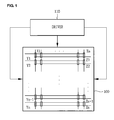
- a plasma display apparatus As shown in Fig. 1, a plasma display apparatus according to an embodiment of the invention comprises a plasma display panel 100 and a driver 110.
- the plasma display panel 100 comprises first electrodes Y1 to Yn, second electrodes Z1 to Zn, and third electrodes X1 to Xm.
- the first electrodes Y1 to Yn and the second electrodes Z1 to Zn are disposed in parallel to each other, and the third electrodes X1 to Xm are disposed so as to cross the first electrodes Y1 to Yn and the second electrodes Z1 to Zn.
- the driver 110 alternately supplies sustain signals to the first electrodes Y1 to Yn and the second electrodes Z1 to Zn and supplies a constant voltage to the third electrodes X1 to Xm.
- the driver 110 alternately supplies sustain signals to the first electrodes Y1 to Yn and the second electrodes Z1 to Zn and supplies an auxiliary signal to the third electrodes X1 to Xm corresponding to at least one of the sustain signals supplied to the first electrodes Y1 to Yn and the second electrodes Z1 to Zn.
- the driver 110 alternately supplies sustain signals to the first electrodes Y1 to Yn and the second electrodes Z1 to Zn and supplies a constant voltage to the third electrodes X1 to Xm.
- the driver 110 alternately supplies sustain signals to the first electrodes Y1 to Yn and the second electrodes Z1 to Zn and supplies an auxiliary signal to the third electrodes X1 to Xm corresponding to at least one of the sustain signals supplied to the first electrodes Y1 to Yn and the second electrodes Z1 to Zn.
- the driver 110 alternately supplies sustain signals to the first electrodes Y1 to Yn and the second electrodes Z1 to Zn and supplies a constant voltage to the third electrodes X1 to Xm.
- the driver 110 alternately supplies sustain signals to the first electrodes Y1 to Yn and the second electrodes Z1 to Zn and floats the third electrodes X1 to Xm corresponding to at least one of the sustain signals supplied to the first electrodes Y1 to Yn and the second electrodes Z1 to Zn.
- a constant voltage may be substantially equal to a ground-level voltage.
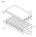
- the plasma display panel of Fig. 2 comprises a front substrate 201, on which the first electrodes 202 and the second electrodes 203 are disposed in parallel to each other, and a rear substrate 211 on which the third electrodes 213 crossing the first electrode and the second electrode 202 and 203 are disposed.
- the first electrodes 202 and the second electrodes 203 are disposed in parallel to each other.
- the first electrode and the second electrode 202 and 203 are covered by an upper dielectric layer 204.
- the upper dielectric layer 204 limits discharge currents of the first electrode and the second electrode 202 and 203.
- the first electrode and the second electrode 202 and 203 are insulated from each other by the upper dielectric layer 204.
- the upper dielectric layer 204 is covered by a protective layer 205.
- the protective layer 205 protects the upper dielectric layer 204, the first electrodes 202, and the second electrodes 203 and discharges secondary electrons.
- the third electrodes 213 are disposed so as to cross the first electrode and the second electrode 202 and 203.
- the third electrodes 213 are covered by a lower dielectric layer 215 by which the third electrodes 213 are insulated from each other.
- barrier ribs 212 are positioned so as to partition discharge cells. Between the barrier ribs 212 and 212, a phosphor layer 214 is positioned.
- the widths of R, G, and B discharge cells may be substantially identical to each other. However, the widths of R, G, and B discharge cells may be different from each other, in order to adjust color temperature.
- the plasma display panel can be formed to have a variety of barrier rib structures as well as the barrier rib structure shown in Fig. 2.
- the barrier rib 212 comprises first and second barrier ribs 212b and 212a, and the heights of the first and second barrier ribs 212b and the 212a may be different from each other.
- a channel which can be used as an exhaust path may be formed in at least one of the first and second barrier ribs 212b and 212a. At least one of the first and second barrier ribs 212b and 212a may have a groove formed therein.
- the respective R, G, and B discharge cells are arranged on the same line
- the R, G, and B discharge cells may be arranged in a triangle shape.
- the discharges cells may be formed in a pentagonal or hexagonal shape as well as a rectangular shape.
- the phosphor layer 214 may further comprise a white (W) layer and/or a yellow (Y) phosphor layer as well as red (R), green (G), and blue (B) phosphor layers.
- W white
- Y yellow
- R red
- G green
- B blue
- the upper and lower dielectric layers 204 and 205 may further comprises one layer and a plurality of layers.
- a black layer (not shown) may be disposed on the barrier rib 212. Further, a black layer (not shown) may be formed on a specific position of the front substrate 201 corresponding to the barrier rib 212.
- first electrode and the second electrode 202 and 203 of Fig. 2 respectively, comprises only a bus electrode
- transparent electrodes 202a and 203a and bus electrodes 202b and 203b may be comprised therein, as shown in Fig. 3.
- black layers 320 and 321 may be respectively disposed, the black layers 320 and 321 preventing light from being reflected.
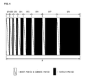
- the plasma display apparatus displays an image in each sub-field of a frame F.
- the frame comprises a plurality of sub-fields SF1 to SF8, each sub-field including a reset period, an address period, and a sustain period.
- a gray level weight is set.
- n 0, 1, 2, 3, 4, 5, 6, 7.
- the number of sustain signals supplied during a sustain period of each sub-field is adjusted in accordance with a gray level weight such that a gray level is represented.
- the frame F of Fig. 4 comprises eight sub-fields but may comprise more than eight sub-fields. Further, in Fig. 4, the sub-fields are arranged in an order where a gray level weight increases. However, the sub-fields may be arranged in an order where a gray level weight decreases or at random.
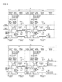
- the plasma display apparatus displays an image during first and second frames F1 and F2.
- Each of the first and second frames F1 and F2 comprises a pre-reset period, a reset period, an address period, and a sustain period.
- the driver 110 of Fig. 1 supplies a first ramp-down signal to the first electrode Y, the first ramp-down signal gradually falling to a first voltage V1. Further, the driver 110 supplies a pre-sustain signal to the second electrode Z, the pre-sustain signal having a reverse polarity to that of the first ramp-down signal.
- the highest voltage of a pre-sustain signal is a pre-sustain voltage Vpz.
- the pre-sustain voltage Vpz can be substantially identical to a sustain voltage which is the highest voltage of a sustain signal SUS.
- the pre-reset period may be comprised in at least one sub-field of the plurality of sub-fields comprised in one frame. Accordingly, it is possible to prevent reduction in driving period, which is caused by the addition of the free reset period. Further, the pre-reset period does not need to be comprised in each of the overall sub-fields.
- the driver 110 supplies a ramp-up signal to the first electrode Y, the ramp-up signal having a reverse polarity to that of the first ramp-down signal.
- the ramp-up signal comprises a first ramp-up signal, which gradually rises from a second voltage V2 to a third voltage V3, and a second ramp-up signal which gradually rises from the third voltage V3 to a fourth voltage V4.
- set-up discharge is generated within the discharge cell. Within the discharge cell, sufficient wall charges are formed by the set-up discharge.
- the slope of the second ramp-up signal may be smaller than that of the first ramp-up signal.
- a voltage rises relatively rapidly before the set-up discharge is generated. Further, while the set-up discharge is generated, a voltage rises relatively slowly. Accordingly, an amount of light generated by the set-up discharge decreases, and a contrast characteristic is improved.
- the driver 110 supplies a second ramp-down signal to the first electrode Y, the second ramp-down signal having a reverse polarity to that of the ramp-up signal.
- the second ramp-down signal gradually falls from a fifth voltage V5 to a sixth voltage V6.
- set-down discharge is generated within the discharge cell.
- the wall charges within the overall discharge cell are uniformized by the set-down discharge.
- the driver 110 supplies a scan bias signal to the first electrode Y.
- the voltage level of the scan bias signal is substantially identical to that of a seventh voltage V7.
- the driver 110 supplies a scan signal to the first electrode Y, the scan signal falling from the seventh voltage V7 to an eighth voltage V8.
- the width of a scan signal in at least one sub-field of the plurality of sub-fields may be different from those of scan signals in the rest of the sub-fields.
- the driver 110 supplies a data signal to the third electrode X.
- the driver 110 supplies a sustain bias signal to the second electrode Z in order to perform stable address discharge during the address period.
- the level of the highest voltage Vz of a sustain bias signal is lower than that of the highest voltage Vs of a sustain signal and is higher than that of a ground voltage GND.
- the waveforms of signals supplied during the pre-reset periods, the reset periods, and the address periods of the first and second frames F1 and F2 are identical to each other, as shown in Fig. 5.
- the number of sustain signals to be assigned to the second frame F2 is larger than the number of sustain signals to be assigned to the first frame F1.
- the number of sustain signals to be assigned to the second frame F2 is N
- the number of sustain signals to be assigned to the first frame F1 is M.
- a second image IMG2 is displayed on an effective region 600 of the plasma display panel.
- a first image IMG1 is displayed on the effective region 600 of the plasma display panel.
- the number of sustain signals to be assigned to the second frame F2 is N
- the number of sustain signals to be assigned to the first frame F1 is M.
- the effective region 600 of the plasma display panel is such a region that can emit light.
- the driver 110 alternately supplies a sustain signal to the first electrode Y and the second electrode Z. Further, the driver 110 supplies an auxiliary signal S to the third electrode X corresponding to at least one of the sustain signals supplied to the first electrode Y and the second electrode Z during the sustain period of the second frame F2.
- an auxiliary signal S is supplied so as to correspond to the sustain signal SUS supplied to the first or second electrode, as shown in Fig. 7.
- the overall supply period of each of the sustain signal SUS and the auxiliary signal S comprises a voltage-rising period, a voltage sustain period, and a voltage-falling period.
- An absolute value of slope of the auxiliary signal in each of the voltage-rising period and the voltage-falling period can be smaller than that of the sustain signal in each of the voltage-rising period and the voltage-falling period.
- the highest voltage V10 of an auxiliary signal may be more than 5V and less than 100V.
- the highest voltage of the sustain signal SUS may range 180V to 250V.
- the ratio of the highest voltage of the sustain signal to the highest voltage of the auxiliary signal may range from 1.8 to 50.
- a sustain signal SUS is supplied to the first or second electrode, and a ground voltage is supplied to the third electrode, as shown in Fig. 7B.
- positive ions in the discharge cell can move to the third electrode.
- the movement of positive ions to the third electrode is caused by a voltage difference between the first electrode and the third electrode or between the second electrode and the third electrodes.
- positive ions are pulled toward the third electrode, the positive ions collide with the phosphor layer such that the phosphor layer is degraded. Further, due to the degradation of the phosphor layer, image sticking occurs on a screen, thereby reducing a lifespan of the plasma display panel.
- a sustain signal is supplied to the first or second electrode during the sustain period as shown in Fig. 7a
- an auxiliary signal is supplied to the third electrode
- a voltage difference between the first electrode and the third electrode or a voltage difference between the second electrode and the third electrodes decreases.
- the auxiliary signal suppresses positive ions from moving toward the third electrode.
- image sticking caused by the degradation of the phosphor layer is suppressed from occurring.
- a lifespan of the plasma display panel is expanded, and driving efficiency and luminance increase.
- the polarity of the auxiliary signal is the same as that of the sustain signal. For example, if the polarity of the sustain signal of Fig. 5 is positive, the polarity of the auxiliary signal is positive.
- the number of sustain signals to be assigned to the second frame is larger than the number of sustain signals to be assigned to the first frame.
- the probability increases that positive ions collide with the phosphor layer. Therefore, the degradation of the phosphor layer increases during the second frame more than during the first frame.
- the driver 110 supplies an auxiliary signal to the third electrode during the second frame, a voltage difference between the first electrode and the third electrode or between the second electrode and the third electrodes decreases. Accordingly, the degradation of the phosphor layer decreases.
- the reason why the absolute value of slope of the auxiliary signal in each of the voltage-rising period and the voltage-falling period is smaller than the absolute value of slope of the sustain signal in each of the voltage-rising period and the voltage-falling period is as follows. If the absolute value of slope of the auxiliary signal in each of the voltage-rising period and the voltage-falling period is larger, the number of positive ions moving from the third electrode to the first or second electrode increases so that sustain discharge can be unstabilized.
- the ratio of the highest voltage of the sustain signal to the highest voltage of the auxiliary signal may range from 1.8 to 50, in order to prevent sustain discharge from being unstabilized when the number of positive ions moving from the third electrode to the first or second electrode increases.
- the driver 110 may supply an auxiliary signal S corresponding to the sustain signals SUS which are alternately supplied to the first electrode and the second electrode. Alternately, the driver 110 may supply an auxiliary signal S corresponding to only the sustain signal supplied to the first electrode. Further, the driver 110 may supply an auxiliary signal corresponding to only the sustain signal supplied to the second electrode.
- the driver 110 can supply an auxiliary signal S2 in at least one sub-field among the plurality of sub-fields of the second frame. For example, as shown in Fig. 5, the driver 110 does not supply an auxiliary signal in the sub-field SF1 of the second frame F2, but can supply an auxiliary signal S in the sub-field SF2 of the second frame F2.
- a distance W1 between the first electrode and the second electrode 202 and 203 can be larger than a distance W2 between the first electrode and the third electrode 202 and 213 or between the second electrode and the third electrodes 203 and 213, as shown in Fig. 8.
- the number of positive ions moving between the first electrode and the third electrode 202 and 213 or between the second electrode and the third electrodes 203 and 213 during the sustain period increases. Therefore, when a sustain signal and an auxiliary signal are supplied during the second frame F2 having a larger APL than the first frame F1, a voltage difference between the first electrode and the third electrode 202 and 213 or between the second electrode and the third electrodes 202 and 213 decreases so that the degradation of the phosphor layer is effectively prevented.
- the distance W1 between the first electrode and the second electrode 202 and 203 of Fig. 8 is equal to or more than 60 ⁇ m, and when an auxiliary signal is supplied, the degradation of the phosphor layer is prevented.
- the distance W1 between the first electrode and the second electrode 202 and 203 is equal to or more than 100 ⁇ m, and when an auxiliary signal is supplied, the degradation of the phosphor layer is prevented more effectively.
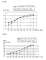
- Fig. 9a when the area of the second image IMG2 of Fig. 6 is equal to or less than 40% of the entire effective region 600 of the plasma display panel, the efficiency when an auxiliary signal is supplied is larger than when an auxiliary signal is not supplied. That is, when the area of the second image IMG2 is equal to or more than 40% of the entire effective region 600 of the plasma display panel, and if an auxiliary signal is not supplied, it may be more effective.
- both of the efficiency and power consumption can be considered.
- an auxiliary signal is not supplied.
- the area of the second image IMG2 of Fig. 6 is less than 60% of the entire effective region 600 of the plasma display panel, an auxiliary signal is supplied.
- the driver 110 of Fig. 1 comprises first and second switches S1 and S2 of Fig. 10a, in order to supply a data signal.
- the driver 110 turns on the first switch S1 so as to supply a high-level data signal to the third electrode. Further, the driver 110 turns on the second switch S2 so as to supply a low-level data signal to the third electrode.
- the driver 110 supplies a sustain signal to the first or second electrode and simultaneously floats the third electrode. That is, the driver 110 turns off the first and second switches S1 and S2 of Fig. 10 so as to float the third electrode. Accordingly, the voltage of the third electrode gradually rises to the highest voltage V10 due to the influence of the sustain signal supplied to the first or second electrode.
- the driver 110 floats the third electrode so as to supply an auxiliary signal. Therefore, the voltage-rising period, the voltage sustain period, and the voltage-falling period of an auxiliary signal are proportional to those of a sustain signal. Further, the width sw of an auxiliary signal is proportional to the width susw of a sustain signal.
- the level of the highest voltage V10 of the auxiliary signal can be lower than that of the highest voltage Vd of a data signal.
Landscapes
- Engineering & Computer Science (AREA)
- Physics & Mathematics (AREA)
- Power Engineering (AREA)
- Plasma & Fusion (AREA)
- Computer Hardware Design (AREA)
- General Physics & Mathematics (AREA)
- Theoretical Computer Science (AREA)
- Control Of Indicators Other Than Cathode Ray Tubes (AREA)
- Control Of Gas Discharge Display Tubes (AREA)
Applications Claiming Priority (1)
| Application Number | Priority Date | Filing Date | Title |
|---|---|---|---|
| KR1020060100547A KR100811472B1 (ko) | 2006-10-16 | 2006-10-16 | 플라즈마 디스플레이 장치 |
Publications (2)
| Publication Number | Publication Date |
|---|---|
| EP1914708A2 true EP1914708A2 (fr) | 2008-04-23 |
| EP1914708A3 EP1914708A3 (fr) | 2010-03-10 |
Family
ID=38925501
Family Applications (1)
| Application Number | Title | Priority Date | Filing Date |
|---|---|---|---|
| EP07250466A Ceased EP1914708A3 (fr) | 2006-10-16 | 2007-02-05 | Appareil d'affichage à plasma |
Country Status (4)
| Country | Link |
|---|---|
| US (1) | US7804465B2 (fr) |
| EP (1) | EP1914708A3 (fr) |
| KR (1) | KR100811472B1 (fr) |
| CN (1) | CN101165755B (fr) |
Cited By (2)
| Publication number | Priority date | Publication date | Assignee | Title |
|---|---|---|---|---|
| WO2011067703A1 (fr) | 2009-12-02 | 2011-06-09 | Koninklijke Philips Electronics N.V. | Contrôle de luminance pour les pixels d'un panneau d'affichage |
| EP2219172A3 (fr) * | 2009-02-17 | 2012-02-22 | Samsung SDI Co., Ltd. | Affichage à plasma et procédé de commande associé |
Citations (2)
| Publication number | Priority date | Publication date | Assignee | Title |
|---|---|---|---|---|
| EP1424679A2 (fr) | 2002-11-29 | 2004-06-02 | Matsushita Electric Industrial Co., Ltd. | Panneau d'affichage à plasma et sa méthode de commande |
| WO2004114270A1 (fr) | 2003-06-23 | 2004-12-29 | Matsushita Electric Industrial Co.,Ltd. | Appareil a ecran plat a plasma et procede de commande correspondant |
Family Cites Families (26)
| Publication number | Priority date | Publication date | Assignee | Title |
|---|---|---|---|---|
| US6376995B1 (en) * | 1998-12-25 | 2002-04-23 | Matsushita Electric Industrial Co., Ltd. | Plasma display panel, display apparatus using the same and driving method thereof |
| JP2000242223A (ja) | 1999-02-23 | 2000-09-08 | Matsushita Electric Ind Co Ltd | プラズマディスプレイパネルの駆動方法及びそれを用いたディスプレイ装置 |
| JP5063841B2 (ja) * | 2001-06-27 | 2012-10-31 | パナソニック株式会社 | プラズマディスプレイパネルの駆動方法 |
| KR20030004602A (ko) | 2001-07-05 | 2003-01-15 | 웹케시 주식회사 | 가상계좌를 이용한 결제 보증 시스템 및 방법, 그프로그램 소스를 기록한 기록매체 |
| KR100472505B1 (ko) * | 2001-11-14 | 2005-03-10 | 삼성에스디아이 주식회사 | 리셋기간에서 중간방전모드를 갖는 플라즈마 디스플레이패널의 구동방법 및 그 장치 |
| KR100438912B1 (ko) * | 2001-12-03 | 2004-07-03 | 엘지전자 주식회사 | 플라즈마 디스플레이 패널의 구동방법 |
| KR20050005682A (ko) | 2003-07-07 | 2005-01-14 | 한국건설기술연구원 | 쇄석을 충전한 투수성 침투구조물 |
| KR100502355B1 (ko) * | 2003-07-12 | 2005-07-21 | 삼성에스디아이 주식회사 | 어드레스 전극 라인들이 전기적으로 플로팅되는 플라즈마디스플레이 패널의 리셋팅 방법, 및 이 리셋팅 방법을사용한 플라즈마 디스플레이 패널의 구동 방법 |
| KR100523846B1 (ko) | 2003-07-14 | 2005-10-26 | 한국지질자원연구원 | 심해저 망간단괴로부터 제조된 매트상의 유가금속 침출방법 |
| KR20050034767A (ko) * | 2003-10-07 | 2005-04-15 | 엘지전자 주식회사 | 플라즈마 디스플레이 패널의 구동방법 |
| KR100589314B1 (ko) * | 2003-11-26 | 2006-06-14 | 삼성에스디아이 주식회사 | 플라즈마 디스플레이 패널의 구동 방법 및 플라즈마 표시장치 |
| KR100523865B1 (ko) * | 2003-12-10 | 2005-10-26 | 엘지전자 주식회사 | 플라즈마 표시 패널의 구동장치 |
| KR20050075216A (ko) * | 2004-01-16 | 2005-07-20 | 엘지전자 주식회사 | 플라즈마 표시 패널에서의 로드 이펙트 상쇄 장치 |
| KR100589316B1 (ko) * | 2004-02-10 | 2006-06-14 | 삼성에스디아이 주식회사 | 플라즈마 표시장치 및 이의 구동방법 |
| US20050264475A1 (en) * | 2004-05-31 | 2005-12-01 | Sang-Hoon Yim | Plasma display device and driving method thereof |
| KR100598175B1 (ko) | 2004-07-01 | 2006-07-10 | 주식회사 하이닉스반도체 | 반도체 소자 및 그 제조 방법 |
| KR100590112B1 (ko) * | 2004-11-16 | 2006-06-14 | 삼성에스디아이 주식회사 | 플라즈마 표시 장치 및 그 구동 방법 |
| KR100908714B1 (ko) * | 2005-01-17 | 2009-07-22 | 삼성에스디아이 주식회사 | 플라즈마 표시 장치 및 그 구동 방법 |
| US20060244685A1 (en) * | 2005-04-27 | 2006-11-02 | Lg Electronics Inc. | Plasma display apparatus and image processing method thereof |
| KR100775830B1 (ko) * | 2005-05-17 | 2007-11-13 | 엘지전자 주식회사 | 플라즈마 디스플레이 패널 장치 및 그 구동 방법 |
| KR100812942B1 (ko) | 2005-07-04 | 2008-03-11 | 주식회사 하이닉스반도체 | 낸드 플래쉬 메모리 소자의 제조방법 |
| KR20070095489A (ko) * | 2005-09-22 | 2007-10-01 | 엘지전자 주식회사 | 플라즈마 디스플레이 장치 |
| KR100774943B1 (ko) * | 2005-10-14 | 2007-11-09 | 엘지전자 주식회사 | 플라즈마 디스플레이 장치 및 그의 구동방법 |
| KR100627416B1 (ko) * | 2005-10-18 | 2006-09-22 | 삼성에스디아이 주식회사 | 플라즈마 표시 장치의 구동 방법 |
| KR100740096B1 (ko) * | 2005-10-21 | 2007-07-16 | 삼성에스디아이 주식회사 | 플라즈마 표시 장치 및 그 구동 방법 |
| JP2009020358A (ja) * | 2007-07-12 | 2009-01-29 | Hitachi Ltd | プラズマディスプレイ装置及び半導体装置 |
-
2006
- 2006-10-16 KR KR1020060100547A patent/KR100811472B1/ko not_active Expired - Fee Related
-
2007
- 2007-02-05 EP EP07250466A patent/EP1914708A3/fr not_active Ceased
- 2007-02-08 CN CN2007100075953A patent/CN101165755B/zh not_active Expired - Fee Related
- 2007-02-09 US US11/672,978 patent/US7804465B2/en not_active Expired - Fee Related
Patent Citations (2)
| Publication number | Priority date | Publication date | Assignee | Title |
|---|---|---|---|---|
| EP1424679A2 (fr) | 2002-11-29 | 2004-06-02 | Matsushita Electric Industrial Co., Ltd. | Panneau d'affichage à plasma et sa méthode de commande |
| WO2004114270A1 (fr) | 2003-06-23 | 2004-12-29 | Matsushita Electric Industrial Co.,Ltd. | Appareil a ecran plat a plasma et procede de commande correspondant |
Non-Patent Citations (1)
| Title |
|---|
| JANG ET AL.: "Improvement of Luminance and Luminous Efficiency Using Address Voltage Pulse During Sustain-Period of AC-PDP", IEEE TRANSACTIONS ON ELECTION DEVICES, vol. 48, no. 9, September 2001 (2001-09-01), pages 1903 - 1910 |
Cited By (2)
| Publication number | Priority date | Publication date | Assignee | Title |
|---|---|---|---|---|
| EP2219172A3 (fr) * | 2009-02-17 | 2012-02-22 | Samsung SDI Co., Ltd. | Affichage à plasma et procédé de commande associé |
| WO2011067703A1 (fr) | 2009-12-02 | 2011-06-09 | Koninklijke Philips Electronics N.V. | Contrôle de luminance pour les pixels d'un panneau d'affichage |
Also Published As
| Publication number | Publication date |
|---|---|
| EP1914708A3 (fr) | 2010-03-10 |
| US20080088541A1 (en) | 2008-04-17 |
| CN101165755A (zh) | 2008-04-23 |
| KR100811472B1 (ko) | 2008-03-07 |
| CN101165755B (zh) | 2010-05-19 |
| US7804465B2 (en) | 2010-09-28 |
Similar Documents
| Publication | Publication Date | Title |
|---|---|---|
| US7804465B2 (en) | Plasma display apparatus | |
| JP2005004213A (ja) | プラズマディスプレイパネルのリセット方法及び装置 | |
| US20060103598A1 (en) | Plasma display panel and method of driving the plasma display panel | |
| EP1868177A2 (fr) | Appareil d'affichage à plasma et son procédé de commande | |
| KR100844819B1 (ko) | 플라즈마 디스플레이 장치 | |
| US20100289789A1 (en) | Plasma display device | |
| WO2008066269A1 (fr) | Appareil d'affichage à plasma et procédé de commande associé | |
| WO2010146827A1 (fr) | Procédé de commande pour panneau d'affichage à plasma, et dispositif d'affichage à plasma | |
| KR100647667B1 (ko) | 플라즈마 디스플레이 패널의 구동방법 | |
| KR20080092749A (ko) | 플라즈마 디스플레이 장치 | |
| EP1930864A2 (fr) | Appareil d'affichage à plasma et procédé de commande correspondant | |
| KR100667589B1 (ko) | 플라즈마 디스플레이 패널의 구동방법 | |
| KR100622697B1 (ko) | 플라즈마 디스플레이 패널의 구동방법 | |
| KR20090043311A (ko) | 플라즈마 디스플레이 장치 | |
| US20070222713A1 (en) | Method of driving plasma display panel | |
| KR20080093589A (ko) | 플라즈마 디스플레이 장치 | |
| KR20090042445A (ko) | 플라즈마 디스플레이 장치 | |
| KR20060102006A (ko) | 플라즈마 디스플레이 패널의 구동방법 | |
| KR20080061000A (ko) | 플라즈마 디스플레이 패널 | |
| KR20090070968A (ko) | 플라즈마 디스플레이 패널의 구동방법 | |
| KR20080062323A (ko) | 플라즈마 디스플레이 장치 | |
| WO2009051396A1 (fr) | Appareil d'affichage à plasma | |
| KR20080014351A (ko) | 플라즈마 디스플레이 장치 | |
| KR20080047930A (ko) | 플라즈마 디스플레이 장치 | |
| KR20080057764A (ko) | 플라즈마 디스플레이 장치 |
Legal Events
| Date | Code | Title | Description |
|---|---|---|---|
| PUAI | Public reference made under article 153(3) epc to a published international application that has entered the european phase |
Free format text: ORIGINAL CODE: 0009012 |
|
| AK | Designated contracting states |
Kind code of ref document: A2 Designated state(s): AT BE BG CH CY CZ DE DK EE ES FI FR GB GR HU IE IS IT LI LT LU LV MC NL PL PT RO SE SI SK TR |
|
| AX | Request for extension of the european patent |
Extension state: AL BA HR MK RS |
|
| PUAL | Search report despatched |
Free format text: ORIGINAL CODE: 0009013 |
|
| AK | Designated contracting states |
Kind code of ref document: A3 Designated state(s): AT BE BG CH CY CZ DE DK EE ES FI FR GB GR HU IE IS IT LI LT LU LV MC NL PL PT RO SE SI SK TR |
|
| AX | Request for extension of the european patent |
Extension state: AL BA HR MK RS |
|
| 17P | Request for examination filed |
Effective date: 20100701 |
|
| AKX | Designation fees paid |
Designated state(s): DE FR GB NL |
|
| 17Q | First examination report despatched |
Effective date: 20110810 |
|
| STAA | Information on the status of an ep patent application or granted ep patent |
Free format text: STATUS: THE APPLICATION HAS BEEN REFUSED |
|
| 18R | Application refused |
Effective date: 20121228 |