EP1930864A2 - Appareil d'affichage à plasma et procédé de commande correspondant - Google Patents
Appareil d'affichage à plasma et procédé de commande correspondant Download PDFInfo
- Publication number
- EP1930864A2 EP1930864A2 EP07250125A EP07250125A EP1930864A2 EP 1930864 A2 EP1930864 A2 EP 1930864A2 EP 07250125 A EP07250125 A EP 07250125A EP 07250125 A EP07250125 A EP 07250125A EP 1930864 A2 EP1930864 A2 EP 1930864A2
- Authority
- EP
- European Patent Office
- Prior art keywords
- electrode
- sustain
- signal
- plasma display
- display apparatus
- Prior art date
- Legal status (The legal status is an assumption and is not a legal conclusion. Google has not performed a legal analysis and makes no representation as to the accuracy of the status listed.)
- Withdrawn
Links
- 238000000034 method Methods 0.000 title claims abstract description 17
- 206010047571 Visual impairment Diseases 0.000 description 21
- 101100137815 Arabidopsis thaliana PRP8A gene Proteins 0.000 description 13
- 101150085660 SUS2 gene Proteins 0.000 description 13
- 101000920618 Homo sapiens Transcription and mRNA export factor ENY2 Proteins 0.000 description 10
- 102100031954 Transcription and mRNA export factor ENY2 Human genes 0.000 description 10
- 239000000758 substrate Substances 0.000 description 10
- 238000010276 construction Methods 0.000 description 9
- 101150000971 SUS3 gene Proteins 0.000 description 7
- 230000004888 barrier function Effects 0.000 description 7
- 238000009826 distribution Methods 0.000 description 6
- 238000004519 manufacturing process Methods 0.000 description 6
- 230000007423 decrease Effects 0.000 description 5
- 230000003247 decreasing effect Effects 0.000 description 5
- OAICVXFJPJFONN-UHFFFAOYSA-N Phosphorus Chemical compound [P] OAICVXFJPJFONN-UHFFFAOYSA-N 0.000 description 4
- 101150065537 SUS4 gene Proteins 0.000 description 2
- CPLXHLVBOLITMK-UHFFFAOYSA-N magnesium oxide Inorganic materials [Mg]=O CPLXHLVBOLITMK-UHFFFAOYSA-N 0.000 description 2
- 239000000395 magnesium oxide Substances 0.000 description 2
- AXZKOIWUVFPNLO-UHFFFAOYSA-N magnesium;oxygen(2-) Chemical compound [O-2].[Mg+2] AXZKOIWUVFPNLO-UHFFFAOYSA-N 0.000 description 2
- 239000000463 material Substances 0.000 description 2
- 230000000630 rising effect Effects 0.000 description 2
- BQCADISMDOOEFD-UHFFFAOYSA-N Silver Chemical compound [Ag] BQCADISMDOOEFD-UHFFFAOYSA-N 0.000 description 1
- 208000032005 Spinocerebellar ataxia with axonal neuropathy type 2 Diseases 0.000 description 1
- 208000033361 autosomal recessive with axonal neuropathy 2 spinocerebellar ataxia Diseases 0.000 description 1
- 238000000151 deposition Methods 0.000 description 1
- AMGQUBHHOARCQH-UHFFFAOYSA-N indium;oxotin Chemical compound [In].[Sn]=O AMGQUBHHOARCQH-UHFFFAOYSA-N 0.000 description 1
- 238000009413 insulation Methods 0.000 description 1
- 238000012986 modification Methods 0.000 description 1
- 230000004048 modification Effects 0.000 description 1
- 230000003287 optical effect Effects 0.000 description 1
- 229910052709 silver Inorganic materials 0.000 description 1
- 239000004332 silver Substances 0.000 description 1
- 238000000638 solvent extraction Methods 0.000 description 1
- 238000002834 transmittance Methods 0.000 description 1
Images







Classifications
-
- G—PHYSICS
- G09—EDUCATION; CRYPTOGRAPHY; DISPLAY; ADVERTISING; SEALS
- G09G—ARRANGEMENTS OR CIRCUITS FOR CONTROL OF INDICATING DEVICES USING STATIC MEANS TO PRESENT VARIABLE INFORMATION
- G09G3/00—Control arrangements or circuits, of interest only in connection with visual indicators other than cathode-ray tubes
- G09G3/20—Control arrangements or circuits, of interest only in connection with visual indicators other than cathode-ray tubes for presentation of an assembly of a number of characters, e.g. a page, by composing the assembly by combination of individual elements arranged in a matrix no fixed position being assigned to or needed to be assigned to the individual characters or partial characters
- G09G3/22—Control arrangements or circuits, of interest only in connection with visual indicators other than cathode-ray tubes for presentation of an assembly of a number of characters, e.g. a page, by composing the assembly by combination of individual elements arranged in a matrix no fixed position being assigned to or needed to be assigned to the individual characters or partial characters using controlled light sources
- G09G3/28—Control arrangements or circuits, of interest only in connection with visual indicators other than cathode-ray tubes for presentation of an assembly of a number of characters, e.g. a page, by composing the assembly by combination of individual elements arranged in a matrix no fixed position being assigned to or needed to be assigned to the individual characters or partial characters using controlled light sources using luminous gas-discharge panels, e.g. plasma panels
- G09G3/288—Control arrangements or circuits, of interest only in connection with visual indicators other than cathode-ray tubes for presentation of an assembly of a number of characters, e.g. a page, by composing the assembly by combination of individual elements arranged in a matrix no fixed position being assigned to or needed to be assigned to the individual characters or partial characters using controlled light sources using luminous gas-discharge panels, e.g. plasma panels using AC panels
- G09G3/291—Control arrangements or circuits, of interest only in connection with visual indicators other than cathode-ray tubes for presentation of an assembly of a number of characters, e.g. a page, by composing the assembly by combination of individual elements arranged in a matrix no fixed position being assigned to or needed to be assigned to the individual characters or partial characters using controlled light sources using luminous gas-discharge panels, e.g. plasma panels using AC panels controlling the gas discharge to control a cell condition, e.g. by means of specific pulse shapes
- G09G3/294—Control arrangements or circuits, of interest only in connection with visual indicators other than cathode-ray tubes for presentation of an assembly of a number of characters, e.g. a page, by composing the assembly by combination of individual elements arranged in a matrix no fixed position being assigned to or needed to be assigned to the individual characters or partial characters using controlled light sources using luminous gas-discharge panels, e.g. plasma panels using AC panels controlling the gas discharge to control a cell condition, e.g. by means of specific pulse shapes for lighting or sustain discharge
-
- G—PHYSICS
- G09—EDUCATION; CRYPTOGRAPHY; DISPLAY; ADVERTISING; SEALS
- G09G—ARRANGEMENTS OR CIRCUITS FOR CONTROL OF INDICATING DEVICES USING STATIC MEANS TO PRESENT VARIABLE INFORMATION
- G09G3/00—Control arrangements or circuits, of interest only in connection with visual indicators other than cathode-ray tubes
- G09G3/20—Control arrangements or circuits, of interest only in connection with visual indicators other than cathode-ray tubes for presentation of an assembly of a number of characters, e.g. a page, by composing the assembly by combination of individual elements arranged in a matrix no fixed position being assigned to or needed to be assigned to the individual characters or partial characters
- G09G3/22—Control arrangements or circuits, of interest only in connection with visual indicators other than cathode-ray tubes for presentation of an assembly of a number of characters, e.g. a page, by composing the assembly by combination of individual elements arranged in a matrix no fixed position being assigned to or needed to be assigned to the individual characters or partial characters using controlled light sources
- G09G3/28—Control arrangements or circuits, of interest only in connection with visual indicators other than cathode-ray tubes for presentation of an assembly of a number of characters, e.g. a page, by composing the assembly by combination of individual elements arranged in a matrix no fixed position being assigned to or needed to be assigned to the individual characters or partial characters using controlled light sources using luminous gas-discharge panels, e.g. plasma panels
- G09G3/288—Control arrangements or circuits, of interest only in connection with visual indicators other than cathode-ray tubes for presentation of an assembly of a number of characters, e.g. a page, by composing the assembly by combination of individual elements arranged in a matrix no fixed position being assigned to or needed to be assigned to the individual characters or partial characters using controlled light sources using luminous gas-discharge panels, e.g. plasma panels using AC panels
- G09G3/291—Control arrangements or circuits, of interest only in connection with visual indicators other than cathode-ray tubes for presentation of an assembly of a number of characters, e.g. a page, by composing the assembly by combination of individual elements arranged in a matrix no fixed position being assigned to or needed to be assigned to the individual characters or partial characters using controlled light sources using luminous gas-discharge panels, e.g. plasma panels using AC panels controlling the gas discharge to control a cell condition, e.g. by means of specific pulse shapes
- G09G3/294—Control arrangements or circuits, of interest only in connection with visual indicators other than cathode-ray tubes for presentation of an assembly of a number of characters, e.g. a page, by composing the assembly by combination of individual elements arranged in a matrix no fixed position being assigned to or needed to be assigned to the individual characters or partial characters using controlled light sources using luminous gas-discharge panels, e.g. plasma panels using AC panels controlling the gas discharge to control a cell condition, e.g. by means of specific pulse shapes for lighting or sustain discharge
- G09G3/2946—Control arrangements or circuits, of interest only in connection with visual indicators other than cathode-ray tubes for presentation of an assembly of a number of characters, e.g. a page, by composing the assembly by combination of individual elements arranged in a matrix no fixed position being assigned to or needed to be assigned to the individual characters or partial characters using controlled light sources using luminous gas-discharge panels, e.g. plasma panels using AC panels controlling the gas discharge to control a cell condition, e.g. by means of specific pulse shapes for lighting or sustain discharge by introducing variations of the frequency of sustain pulses within a frame or non-proportional variations of the number of sustain pulses in each subfield
-
- G—PHYSICS
- G09—EDUCATION; CRYPTOGRAPHY; DISPLAY; ADVERTISING; SEALS
- G09G—ARRANGEMENTS OR CIRCUITS FOR CONTROL OF INDICATING DEVICES USING STATIC MEANS TO PRESENT VARIABLE INFORMATION
- G09G3/00—Control arrangements or circuits, of interest only in connection with visual indicators other than cathode-ray tubes
- G09G3/20—Control arrangements or circuits, of interest only in connection with visual indicators other than cathode-ray tubes for presentation of an assembly of a number of characters, e.g. a page, by composing the assembly by combination of individual elements arranged in a matrix no fixed position being assigned to or needed to be assigned to the individual characters or partial characters
- G09G3/22—Control arrangements or circuits, of interest only in connection with visual indicators other than cathode-ray tubes for presentation of an assembly of a number of characters, e.g. a page, by composing the assembly by combination of individual elements arranged in a matrix no fixed position being assigned to or needed to be assigned to the individual characters or partial characters using controlled light sources
- G09G3/28—Control arrangements or circuits, of interest only in connection with visual indicators other than cathode-ray tubes for presentation of an assembly of a number of characters, e.g. a page, by composing the assembly by combination of individual elements arranged in a matrix no fixed position being assigned to or needed to be assigned to the individual characters or partial characters using controlled light sources using luminous gas-discharge panels, e.g. plasma panels
- G09G3/288—Control arrangements or circuits, of interest only in connection with visual indicators other than cathode-ray tubes for presentation of an assembly of a number of characters, e.g. a page, by composing the assembly by combination of individual elements arranged in a matrix no fixed position being assigned to or needed to be assigned to the individual characters or partial characters using controlled light sources using luminous gas-discharge panels, e.g. plasma panels using AC panels
- G09G3/296—Driving circuits for producing the waveforms applied to the driving electrodes
-
- G—PHYSICS
- G09—EDUCATION; CRYPTOGRAPHY; DISPLAY; ADVERTISING; SEALS
- G09G—ARRANGEMENTS OR CIRCUITS FOR CONTROL OF INDICATING DEVICES USING STATIC MEANS TO PRESENT VARIABLE INFORMATION
- G09G2310/00—Command of the display device
- G09G2310/06—Details of flat display driving waveforms
- G09G2310/066—Waveforms comprising a gently increasing or decreasing portion, e.g. ramp
-
- G—PHYSICS
- G09—EDUCATION; CRYPTOGRAPHY; DISPLAY; ADVERTISING; SEALS
- G09G—ARRANGEMENTS OR CIRCUITS FOR CONTROL OF INDICATING DEVICES USING STATIC MEANS TO PRESENT VARIABLE INFORMATION
- G09G2320/00—Control of display operating conditions
- G09G2320/02—Improving the quality of display appearance
- G09G2320/0257—Reduction of after-image effects
-
- G—PHYSICS
- G09—EDUCATION; CRYPTOGRAPHY; DISPLAY; ADVERTISING; SEALS
- G09G—ARRANGEMENTS OR CIRCUITS FOR CONTROL OF INDICATING DEVICES USING STATIC MEANS TO PRESENT VARIABLE INFORMATION
- G09G2320/00—Control of display operating conditions
- G09G2320/10—Special adaptations of display systems for operation with variable images
- G09G2320/103—Detection of image changes, e.g. determination of an index representative of the image change
-
- G—PHYSICS
- G09—EDUCATION; CRYPTOGRAPHY; DISPLAY; ADVERTISING; SEALS
- G09G—ARRANGEMENTS OR CIRCUITS FOR CONTROL OF INDICATING DEVICES USING STATIC MEANS TO PRESENT VARIABLE INFORMATION
- G09G2360/00—Aspects of the architecture of display systems
- G09G2360/16—Calculation or use of calculated indices related to luminance levels in display data
-
- G—PHYSICS
- G09—EDUCATION; CRYPTOGRAPHY; DISPLAY; ADVERTISING; SEALS
- G09G—ARRANGEMENTS OR CIRCUITS FOR CONTROL OF INDICATING DEVICES USING STATIC MEANS TO PRESENT VARIABLE INFORMATION
- G09G3/00—Control arrangements or circuits, of interest only in connection with visual indicators other than cathode-ray tubes
- G09G3/20—Control arrangements or circuits, of interest only in connection with visual indicators other than cathode-ray tubes for presentation of an assembly of a number of characters, e.g. a page, by composing the assembly by combination of individual elements arranged in a matrix no fixed position being assigned to or needed to be assigned to the individual characters or partial characters
- G09G3/22—Control arrangements or circuits, of interest only in connection with visual indicators other than cathode-ray tubes for presentation of an assembly of a number of characters, e.g. a page, by composing the assembly by combination of individual elements arranged in a matrix no fixed position being assigned to or needed to be assigned to the individual characters or partial characters using controlled light sources
- G09G3/28—Control arrangements or circuits, of interest only in connection with visual indicators other than cathode-ray tubes for presentation of an assembly of a number of characters, e.g. a page, by composing the assembly by combination of individual elements arranged in a matrix no fixed position being assigned to or needed to be assigned to the individual characters or partial characters using controlled light sources using luminous gas-discharge panels, e.g. plasma panels
- G09G3/288—Control arrangements or circuits, of interest only in connection with visual indicators other than cathode-ray tubes for presentation of an assembly of a number of characters, e.g. a page, by composing the assembly by combination of individual elements arranged in a matrix no fixed position being assigned to or needed to be assigned to the individual characters or partial characters using controlled light sources using luminous gas-discharge panels, e.g. plasma panels using AC panels
- G09G3/291—Control arrangements or circuits, of interest only in connection with visual indicators other than cathode-ray tubes for presentation of an assembly of a number of characters, e.g. a page, by composing the assembly by combination of individual elements arranged in a matrix no fixed position being assigned to or needed to be assigned to the individual characters or partial characters using controlled light sources using luminous gas-discharge panels, e.g. plasma panels using AC panels controlling the gas discharge to control a cell condition, e.g. by means of specific pulse shapes
- G09G3/292—Control arrangements or circuits, of interest only in connection with visual indicators other than cathode-ray tubes for presentation of an assembly of a number of characters, e.g. a page, by composing the assembly by combination of individual elements arranged in a matrix no fixed position being assigned to or needed to be assigned to the individual characters or partial characters using controlled light sources using luminous gas-discharge panels, e.g. plasma panels using AC panels controlling the gas discharge to control a cell condition, e.g. by means of specific pulse shapes for reset discharge, priming discharge or erase discharge occurring in a phase other than addressing
- G09G3/2927—Details of initialising
Definitions
- This document relates to a display apparatus and, more particularly, to a plasma display apparatus and a driving method thereof.
- a plasma display apparatus of a display apparatus has a plasma display panel and a driver for driving the plasma display panel.
- the plasma display panel has phosphors formed within discharge cells partitioned by barrier ribs, and a plurality of electrodes.
- the driver applies a driving signal to the discharge cells through the electrodes.
- Discharge is generated within each discharge cell by means of the driving signal.
- a discharge gas filled within the discharge cell generates vacuum ultraviolet rays.
- the vacuum ultraviolet rays emit the phosphors formed within the discharge cell, generating a visible ray.
- An image is displayed on the screen of the plasma display panel by means of the visible ray.
- the conventional plasma display apparatus is problematic in that an afterimage is generated when an image is implemented on the screen.
- An aspect of this document is to provide a plasma display apparatus and a driving method thereof, in which the occurrence of an afterimage can be decreased.
- a plasma display apparatus comprises a plasma display panel comprising a first electrode and a second electrode, and a driver for applying a plurality of sustain signals to the second electrode while applying two consecutive sustain signals to the first electrode in a sustain period.
- a method of driving a plasma display apparatus comprises applying a first sustain signal to a first electrode in a sustain period, after the first sustain signal is applied to the first electrode, applying a plurality of sustain signals to a second electrode, and after the plurality of sustain signals are applied to the second electrode, applying a second sustain signal consecutive to the first sustain signal to the first electrode.
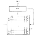
- FIG. 1 is a view illustrating the construction of a plasma display apparatus according to an embodiment of the present invention.
- a plasma display apparatus according to an embodiment of the present invention comprises a plasma display panel 100 and a driver 110.
- the driver 110 applies a sustain signal to a first electrode and a second electrode of the plasma display panel 100 in a sustain period, and also applies a plurality of sustain signals to the second electrode while applying two consecutive sustain signals to the first electrode.
- the driver 110 is formed in one board fashion. It is, however, to be noted that the driver 110 of the plasma display apparatus according to an embodiment of the present invention can be divided into a plurality of board forms depending on electrodes formed in the plasma display panel 100.
- the driver 110 can be divided into a first driver (not shown) for driving the first electrode, a second driver (not shown) for driving the second electrode, and a third driver (not shown) for driving the third electrodes.
- the driver 110 of the plasma display apparatus will become more evident from subsequent descriptions.
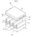
- FIGS. 2a and 2b are views illustrating the construction of the plasma display panel comprised in the plasma display apparatus according to an embodiment of the present invention.
- the plasma display panel 100 comprises a front panel 200 comprising a front substrate 201 in which electrodes, that is, a first electrode 202 and a second electrode 203 parallel to each other are formed, and a rear panel 210 comprising a front substrate 211 in which third electrodes 213 crossing the first electrode 202 and the second electrode 203 are formed.
- the front panel 200 and the rear panel 210 may be coalesced together.
- the first electrode 202 and the second electrode 203 formed on the front substrate 201 can generate discharge in a discharge space, that is, a discharge cell, and can also sustain the discharge of the discharge cell.
- a dielectric layer to cover the first electrode 202 and the second electrode 203, for example, an upper dielectric layer 204 can be formed on the front substrate 201 on which the first electrode 202 and the second electrode 203 are formed.
- the upper dielectric layer 204 can limit the discharge currents of the first electrode 202 and the second electrode 203, and can provide insulation between the first electrode 202 and the second electrode 203.
- a protection layer 205 for facilitating discharge conditions.
- the protection layer 205 can be formed by a method of depositing Magnesium Oxide (MgO), etc. on the upper dielectric layer 204 or the like.
- MgO Magnesium Oxide
- the third electrodes 213 formed on the front substrate 211 are electrodes for applying a data signal to the discharge cell.
- a dielectric layer to cover the third electrodes 213, for example, a lower dielectric layer 215 can be formed on a top surface of the front substrate 211 in which the third electrodes 213 are formed.
- the lower dielectric layer 215 can insulate the third electrodes 213.
- Barrier ribs 212 of a stripe type, a well type, a delta type, a beehive type or the like, for partitioning discharge spaces, that is, discharge cells can be formed on the lower dielectric layer 215.
- discharge cells of red (R), green (G), blue (B) and so on can be formed between the front substrate 201 and the front substrate 211.
- a specific discharge gas can be filled within each of the discharge cells partitioned by the barrier ribs 212.
- a phosphor layer 214 that emits a visible ray for image display at the time of address discharge can also be formed within each of the discharge cells partitioned by the barrier ribs 212.
- R, G, and B phosphor layers can be formed within the discharge cells.
- discharge can be generated within the discharge cells partitioned by the barrier ribs 212.
- vacuum ultraviolet rays are generated from the discharge gas filled within the discharge cell.
- the vacuum ultraviolet rays are applied to the phosphor layers 214 formed within the discharge cells.
- a visible ray is generated from each phosphor layer 214.
- the generated visible ray is discharged externally through the front substrate 201 in which the upper dielectric layer 204 is formed, so that an image can be displayed on an exterior surface of the front substrate 201.
- each of the first electrode 202 and the second electrode 203 has only one layer.
- one or more of the first electrode 202 and the second electrode 203 can have a plurality of layers. This example is described below with reference to FIG. 2b.
- each of the first electrode 202 and the second electrode 203 can have two layers.
- the first electrode 202 and the second electrode 203 can comprise bus electrodes 202b and 203b made of opaque silver (Ag) material, and transparent electrodes 202a and 203a made of transparent Indium Tin Oxide (ITO) material.
- bus electrodes 202b and 203b made of opaque silver (Ag) material
- transparent electrodes 202a and 203a made of transparent Indium Tin Oxide (ITO) material.
- first electrode 202 and the second electrode 203 comprise the transparent electrodes 202a and 203a, respectively, as described above is that a visible ray generated within the discharge cells can be effectively discharged outside the plasma display panel.
- the reason why the first electrode 202 and the second electrode 203 comprise the bus electrodes 202b and 203b, respectively, is as follows.
- electrical conductivity of the transparent electrodes 202a and 203a is relatively low and driving efficiency can be decreased accordingly.
- such low electrical conductivity of the transparent electrodes 202a and 203a which may cause a decrease in driving efficiency, can be compensated for by the bus electrodes 202b and 203b.
- black layers 220 and 221 may be further provided between the transparent electrode 202a and the bus electrode 202b, and between the transparent electrode 203a and the bus electrode 203b, respectively, in order to prevent reflection of external light by the bus electrodes 202b and 203b.
- the transparent electrodes 202a and 203a may be omitted. In other words, an ITO-less construction is possible.
- the first electrode 202 and the second electrode 203 may comprise only the bus electrodes 202b and 203b without the transparent electrodes 202a and 203a in FIG. 2b.
- the first electrode 202 and the second electrode 203 may comprise one layer of the bus electrodes 202b and 203b.
- FIGS. 2a and 2b only an example of the plasma display panel of the present invention has been shown and described. It is, however, to be understood that the present invention is not limited to the plasma display panel having the construction as shown in FIGS. 2a and 2b.
- each of the upper dielectric layer 204 and the lower dielectric layer 215 has only one layer.
- at least one of the upper dielectric layer 204 and the lower dielectric layer 215 may have a plurality of layers.
- a black layer (not shown), which can absorb external light, may be further formed on the barrier ribs 212.
- the construction of the plasma display panel applied to the plasma display apparatus according to an embodiment of the present invention may be changed in various ways.
- FIG. 3 is a view illustrating a frame for implementing gray levels of an image in the plasma display apparatus according to an embodiment of the present invention.
- FIG. 4 is a view illustrating the operation of the plasma display apparatus according to an embodiment of the present invention.
- a frame for implementing gray levels of an image is divided into several subfields having a different number of emissions.
- each subfield can be divided into a reset period for resetting the entire discharge cells, an address period for selecting a discharge cell to be discharged, and a sustain period for implementing gray levels depending on the number of discharges.
- a frame period (16.67ms) corresponding to 1/60 seconds is divided into eight subfields SF1 to SF8, and each of the eight subfields SF1 to SF8 is divided into a reset period, an address period and a sustain period, as shown in FIG. 3.
- a gray level weight of a corresponding subfield can be set by controlling the number of sustain signals supplied in the sustain period.
- a specific gray level weight may be assigned to each subfield by employing the sustain period.
- Gray levels of various images can be implemented by controlling the number of sustain signals supplied in the sustain period of each subfield depending on a gray level weight in each subfield as described above.
- the plasma display apparatus uses a plurality of frames in order to display an image of 1 second. For example, 60 frames are used to display an image of 1 second.
- one frame comprises eight subfields. It is however to be understood that the number of subfields constituting one frame may be changed in various ways.
- 12 subfields from a first subfield to a twelfth subfield may form one frame
- 10 subfields may form one frame or the like.
- the picture quality of an image implemented by the plasma display apparatus that implement gray levels of an image using the frame may be decided depending on the number of subfields comprised in the frame. In other words, when the number of subfields comprised in a frame is 12, gray levels of an image of 212 kinds can be represented. When the number of subfields comprised in a frame is 8, gray levels of an image of 28 kinds can be represented.
- the subfields are arranged in order of increasing gray level weights in one frame.
- the subfields can be arranged in order of decreasing gray level weights in one frame, or can be arranged regardless of gray level weights.
- FIG. 4 there is shown the operation of the plasma display apparatus in any one of the plurality of subfields comprised in the frame as shown in FIG. 3 according to an embodiment of the present invention.
- the driver 110 shown in FIG. 1 may apply a first ramp-down signal to the first electrode in a pre-reset period anterior to the reset period.
- the driver 110 may apply a pre-sustain signal having an opposite polarity to that of the first ramp-down signal to the second electrode while the first ramp-down signal is applied to the first electrode.
- the first ramp-down signal applied to the first electrode may gradually fall up to a tenth voltage V10.
- the first ramp-down signal may gradually fall from a voltage of a ground level GND.
- the pre-sustain signal may maintain a pre-sustain voltage Vpz substantially constantly.
- the pre-sustain voltage Vpz may be substantially the same voltage as a voltage of a sustain signal SUS applied in the subsequent sustain period, that is, a sustain voltage Vs.
- first ramp-down signal is applied to the first electrode and the pre-sustain signal is applied to the second electrode in the pre-reset period as described above
- wall charges having a specific polarity are accumulated on the first electrode
- wall charges having an opposite polarity to that of the first electrode are accumulated on the second electrode.
- positive (+) wall charges may be accumulated on the first electrode
- negative (-) wall charges may be accumulated on the second electrode.
- the above-described pre-reset period may be comprised anterior to the reset period in the whole subfields of the frame.
- the pre-reset period may be comprised anterior to the reset period in one of subfields of a frame, which has the smallest gray level weight, or the pre-reset period may be comprised anterior to the reset period in two or three of subfields of a frame.
- the pre-reset period may be omitted in the whole subfields.
- the driver 110 may apply a ramp-up signal having an opposite polarity to that of the first ramp-down signal to the first electrode.
- the ramp-up signal may comprise a first ramp-up signal gradually rising from a twentieth voltage V20 to a thirtieth voltage V30 with a first slope, and a second ramp-up signal gradually rising from the thirtieth voltage V30 to a fortieth voltage V40 with a second slope.
- weak dark discharge that is, set-up discharge is generated within the discharge cell by means of the ramp-up signal.
- the set-up discharge causes some degree of wall charges to be accumulated within the discharge cell.
- the second slope of the second ramp-up signal may be smoother than the first slope. If the second slope is smoother than the first slope as described above, voltage can rise relatively rapidly before the set-up discharge is generated, and voltage can rise relatively slowly while the set-up discharge is generated. Accordingly, the amount of light generated by the set-up discharge can be decreased.
- the driver 110 may apply a second ramp-down signal having an opposite polarity to that of the ramp-up signal to the first electrode after the ramp-up signal.
- the second ramp-down signal may gradually fall from the twentieth voltage V20 to a fiftieth voltage V50.
- the set-down discharge causes wall charges of the degree that address discharge can be generated stably to uniformly remain within the discharge cell.
- the ramp-up signal or the second ramp-down signal may be set differently from that of FIG. 4. This example is described below with reference to FIGS. 5a and 5b.
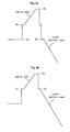
- FIGS. 5a and 5b are views illustrating another forms of the ramp-up signal or the second ramp-down signal.
- a ramp-up signal abruptly rises up to a thirtieth voltage V30 and then gradually rises from the thirtieth voltage V30 to a fortieth voltage V40.
- the ramp-up signal may be changed in various ways, such as that the ramp-up signal gradually rises with different slopes in two steps as in FIG. 4 and the ramp-up signal gradually rises in one step as in FIG. 5a.
- a voltage of a second ramp-down signal gradually falls from a thirtieth voltage V30.
- a point of time at which a voltage of the second ramp-down signal falls may be changed in various ways, such as that a point of time at which a voltage of the second ramp-down signal falls is set differently.
- FIGS. 5a and 5b Description about FIGS. 5a and 5b is thereby completed.
- the driver 110 may apply a scan bias signal whose voltage substantially keeps higher than the fiftieth voltage V50 of the second ramp-down signal to the first electrode.
- a scan signal Scan that falls from the scan bias signal as much as a scan voltage ⁇ vy may be applied to the entire first electrodes Y1 to Yn.
- a first scan signal Scan 1 may be applied to a first first electrode Y1 of the plurality of first electrodes
- a second scan signal Scan 2 may be applied to a second first electrode Y2 of the plurality of first electrodes
- a n th scan signal Scan n may be applied to a n th first electrode Yn of the plurality of first electrodes.
- address discharge is generated within a discharge cell to which the data voltage ⁇ Vd of the data signal is applied as a difference between the scan voltage ⁇ vy of the scan signal Scan and the data voltage ⁇ Vd of the data signal and a wall voltage by wall charges generated in the reset period are added.
- Wall charges of the degree that sustain discharge can be generated when the sustain signal SUS is applied in the subsequent sustain period are formed within a discharge cell selected by the address discharge.
- the driver 110 may apply a sustain bias signal to the second electrode in the address period in order to prevent the address discharge from becoming unstable due to the interference of the second electrode.
- the sustain bias signal can substantially constantly sustain a sustain bias voltage Vz, which is lower than the voltage of the sustain signal applied in the sustain period, but higher than the voltage of the ground level GND.
- the driver 110 may apply the sustain signal SUS to one or more of the first electrode and the second electrode in the sustain period for image display.
- the driver 110 can alternately apply the sustain signal SUS to the first electrode and the second electrode.
- the sustain signal SUS can have the amount of voltage as much as ⁇ Vs.
- sustain discharge that is, display discharge is generated between the first electrode and the second electrode of the discharge selected by the address discharge whenever the sustain signal SUS is applied as a wall voltage within the discharge cell and the sustain voltage ⁇ Vs of the sustain signal SUS are added. Accordingly, an image can be implemented on the plasma display panel.
- the sustain signal applied to the first electrode and the second electrode in the sustain period is described in more detail below.
- FIGS. 6a to 6c are views illustrating, in more detail, the sustain signal applied to the first electrode and the second electrode in the sustain period.
- the number of sustain signals applied to the first electrode and the number of sustain signals applied to the second electrode are different from each other.
- the number of the sustain signals applied to the first electrode can be 7 from 1 to 7
- the number of the sustain signals applied to the second electrode can be 6 from 1 to 6.
- the number of the sustain signals applied to the first electrode is greater than the number of the sustain signals applied to the second electrode.
- the number of the sustain signals applied to the first electrode can be smaller than or the same as the number of the sustain signals applied to the second electrode.
- a method of making different the number of the sustain signals applied to the first electrode and the number of the sustain signals applied to the second electrode may be changed in various ways.
- the number of sustain signals applied to the first electrode can be set different from the number of sustain signals applied to the second electrode in such a manner that two or more sustain signals SUSZ1 and SUSZ2 are consecutively applied to the second electrode while two consecutive sustain signals SUSY1 and SUSY2 are applied to the first electrode.
- the sustain signal SUSZ1 and the sustain signal SUSZ2 can be consecutively applied to the second electrode before the sustain signal SUSY2 is applied to the first electrode since the sustain signal SUSY1 is applied to the first electrode.
- the two sustain signals applied to the first electrode that is, the sustain signal SUSY1 and the sustain signal SUSY2 are neighboring sustain signals.
- a distance from when the sustain signal SUSY1 is applied to the first electrode to when the sustain signal SUSY2 is applied to the first electrode can be 1.5 to 5 times that from when the sustain signal SUSZ1 is applied to the second electrode to when the sustain signal SUSZ2 is applied to the second electrode.
- the reason why the distance from when the sustain signal SUSY1 is applied to the first electrode to when the sustain signal SUSY2 is applied to the first electrode is 5 times smaller than that from when the sustain signal SUSZ1 is applied to the second electrode to when the sustain signal SUSZ2 is applied to the second electrode is as follows. As a duration time of a specific mode increases, the distributions of wall charges can be further adhered. In this case, the occurrence of an afterimage can be prohibited to the greatest extent possible by shaking the adhesion of wall charges.
- the reason why the distance from when the sustain signal SUSY1 is applied to the first electrode to when the sustain signal SUSY2 is applied to the first electrode is 1.5 times greater than that from when the sustain signal SUSZ1 is applied to the second electrode to when the sustain signal SUSZ2 is applied to the second electrode is that it can prevent a decrease in a luminance characteristic while prohibiting the occurrence of an afterimage.
- the number of sustain signals applied to the first electrode and the number of sustain signals applied to the second electrode can be set differently in such a manner that any sustain signals are not applied to the second electrode while two sustain signals SUSY1 and SUSY2, which are adjacent and consecutive to each other, to the first electrode.
- any sustain signals are not applied to the second electrode in a period from when the sustain signal SUSY1 is applied to the first electrode to when the sustain signal SUSY2 is applied to the first electrode.
- the sustain signal SUSY1 and the sustain signal SUSY2 are continuously applied to the first electrode in a period from when the sustain signal SUSY1 is applied to the second electrode to when the sustain signal SUSY2 is applied to the second electrode.
- a distance from when the sustain signal SUSY1 is applied to the second electrode to when the sustain signal SUSY2 is applied to the second electrode can be 1.5 to 5 times that from when the sustain signal SUSZ1 is applied to the first electrode to when the sustain signal SUSZ2 is applied to the first electrode.
- the reason why the from when the sustain signal SUSY1 is applied to the second electrode to when the sustain signal SUSY2 is applied to the second electrode is 5 times smaller than that from when the sustain signal SUSZ1 is applied to the first electrode to when the sustain signal SUSZ2 is applied to the first electrode is as follows. As a duration time of a specific mode increases, the distributions of wall charges can be further adhered. In this case, the occurrence of an afterimage can be prohibited to the greatest extent possible by shaking the adhesion of wall charges.
- the reason why the from when the sustain signal SUSY1 is applied to the second electrode to when the sustain signal SUSY2 is applied to the second electrode is 1.5 times greater than that from when the sustain signal SUSZ1 is applied to the first electrode to when the sustain signal SUSZ2 is applied to the first electrode is that it can prevent a decrease in a luminance characteristic while prohibiting the occurrence of an afterimage.
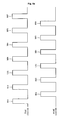
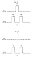
- FIGS. 7a and 7b are views illustrating, in more detail, a method of making different the number of sustain signals applied to the first electrode and the number of sustain signals applied to the second electrode.
- FIG. 7a illustrates an example in which the number of sustain signals applied to the first electrode is greater than the number of sustain signals applied to the second electrode, as in FIG. 6c.
- a first sustain signal SUS1 is first applied to the first electrode
- a second sustain signal SUS2 is applied to the second electrode
- a third sustain signal SUS3 is then applied to the first electrode in the sustain period, as in (a) of FIG. 7a.
- the third sustain signal SUS3 can be applied to the first electrode in a state where the second sustain signal SUS2 to be applied to the second electrode is omitted after the first sustain signal SUS1 is applied to the first electrode in the sustain period as in (b) of FIG. 7a.
- the number of the sustain signals applied to the first electrode can be increased by omitting the second sustain signal SUS2 to be applied to the second electrode.
- FIG. 7b illustrates an example in which the number of sustain signals applied to the second electrode is greater than the number of sustain signals applied to the first electrode, as in FIG. 6b.
- a first sustain signal SUS1 is first applied to the second electrode
- a second sustain signal SUS2 is applied to the first electrode
- a third sustain signal SUS3 is then applied to the second electrode in the sustain period, as in (a) of FIG. 7b.
- the third sustain signal SUS3 can be applied to the second electrode in a state where the second sustain signal SUS2 to be applied to the first electrode is omitted after the first sustain signal SUS1 is applied to the second electrode in the sustain period as in (b) of FIG. 7b.
- the number of the sustain signals applied to the second electrode can be increased by omitting the second sustain signal SUS2 to be applied to the first electrode.
- the number of sustain signals applied to the first electrode is set different from the number of sustain signals applied to the second electrode as described above, the occurrence of an afterimage can be decreased. This is described below with reference to FIGS. 8a and 8b.
- FIGS. 8a and 8b are views illustrating a reason why the number of sustain signals applied to the first electrode is set different from the number of sustain signals applied to the second electrode.
- FIG. 8a illustrates an example in which the same number of sustain signals are applied to the first electrode and the second electrode.
- an image 810 such as "A”
- a screen 800 as shown in (a) of FIG. 8a.
- FIG. 8b illustrates an example in which the number of sustain signals applied to the first electrode is different from the number of sustain signals applied to the second electrode.
- the second sustain signal to be applied to the second electrode is omitted.
- a method of making different the number of sustain signals applied to the first electrode and the number of sustain signals applied to the second electrode can be applied in a specific mode.
- the number of sustain signals applied to the first electrode is set to be the same as the number of sustain signals applied to the second electrode in a common mode, whereas the number of sustain signals applied to the first electrode is set different from the number of sustain signals applied to the second electrode in a specific mode.
- the specific mode may be a mode sensitive to an afterimage.
- a mode having conditions in which the afterimage can occur easily can be set to the specific mode.
- the specific mode may be a mode in which substantially the same image is displayed on a specific cell for a critical time or more.
- the cell can also be interpreted as a specific region on the screen.
- the specific mode may be a mode in which an image having substantially the same APL is displayed on a specific cell for a critical time or more.
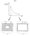
- FIG. 9 is a view illustrating, in more detail, the APL.
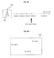
- FIGS. 10a and 10b are views illustrating, in more detail, an example of the specific mode.
- the APL is decided depending on the number of discharge cells, which are turned on, of discharge cells of a plasma display panel 900. In other words, the APL is decided depending on an area on which an image is displayed on the plasma display panel 900.
- the number of sustain signals per gray level decreases, and as the value of the APL decreases, the number of sustain signals per gray level increases.
- the whole power consumption can be reduced by making relatively small the number of sustain signals per gray level, which are supplied to each discharge cell contributing to image display because the number of discharge cells contributing to image display is relatively large.
- the number of sustain signals per gray level accordingly can be N.
- the number of sustain signals per gray level accordingly can be M smaller than N.
- the specific mode can be set depending on the APL.
- FIGS. 10a and 10b illustrate examples of a specific afterimage mode.
- a mode can be set to a specific mode in which the number of sustain signals applied to the first electrode and the number of sustain signals applied to the second electrode are set differently depending on a duration time at which the image 1010 is displayed.
- the specific mode may start beginning a point of time at which the image 1010 of "A" continues on the plasma display panel 1000 for a critical time, for example, 4 minutes.
- the specific mode may correspond to a case where the same image is displayed on a specific cell for a critical time or more, that is, a case where substantially the same image is continuously displayed on the plasma display panel 1000 for a critical time or more.
- the mode can be set to the specific mode in the case where an image having substantially the same APL, as described in FIG. 9, is displayed for a critical time or more.
- a critical time at which the image having substantially the same APL is continuously displayed may be set to range from approximately 30 seconds to 10 minutes.
- FIG. 10b illustrates another method of setting the specific mode.
- a no-signal mode can also be set to a specific mode in which the number of sustain signals applied to the first electrode is set different from the number of sustain signals applied to the second electrode. This is described below.
- OSD On Screen Display
- the OSD at the time of no signal can also generate an afterimage in the same manner as the above. Accordingly, at the time of no signal, the number of sustain signals applied to the first electrode can be set different from the number of sustain signals applied to the second electrode as in the present invention.
- a difference between the number of sustain signals applied to the first electrode and the number of sustain signals applied to the second electrode can be set differently by taking the duration time of the specific mode into consideration.
- FIG. 11 is a view illustrating an exemplary method of controlling the number of sustain signals depending on the duration time of the specific mode.
- the 9 sustain signal and the 19 sustain signal applied to the first electrode can be omitted as shown in (b) of FIG. 11.
- the duration time of the specific mode is a first critical time, for example, 4 minutes or more
- the 5 sustain signal, the 11 sustain signal and the 17 sustain signal applied to the first electrode can be omitted as shown in (c) of FIG. 11.
- the duration time of the specific mode is the first critical time, for example, 4 minutes or more as shown in (c)
- three of the 20 sustain signals can be omitted compared with the case where the specific mode is entered as shown in (b).
- the duration time of the specific mode is a second critical time, for example, 8 minutes or more
- the 3 sustain signal, the 7 sustain signal, the 11 sustain signal, the 15 sustain signal and the 19 sustain signal applied to the first electrode can be omitted as shown in (d) of FIG. 11.
- the duration time of the specific mode is the second critical time, for example, 8 minutes or more as shown in (d)
- five of the 20 sustain signals can be omitted compared with the case where the duration time of the specific mode is the first critical time, for example, 4 minutes or more as shown in (c).
- the number of sustain signals, which are omitted as the duration time of the specific mode increases is increased. This is because if the duration time of the specific mode increases, the distributions of wall charges within a discharge cell are further adhered and, as a result, the occurrence of an afterimage can be further increased.
- sustain signals applied to either the first electrode or the second electrode are omitted. It is however to be noted that one or more of sustain signals applied to the first electrode and one or more of sustain signals applied to the second electrode can be omitted together. An example of which is described below.
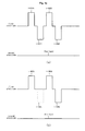
- FIG. 12 is a view illustrating an exemplary method of omitting one or more of sustain signals applied to the first electrode and one or more of sustain signals applied to the second electrode at the same time.
- FIG. 12 can be applied to a case that is further sensitive to an afterimage.
- FIG. 13 is a view illustrating continuous omission of two or more sustain signals.
- a second sustain signal SUS2 to be applied to the second electrode can be omitted, and after a third sustain signal SUS3 is applied to the first electrode, a fourth sustain signal SUS4 can be applied to the second electrode, as shown in (a) of FIG. 13.
- a next sustain signal can be applied to the first electrode different from the second electrode.
- the fourth sustain signal SUS4 can be then applied to the second electrode, as shown in (b) of FIG. 13.
- the omitted sustain signals can be selected in various ways.
- the sustain signal is alternately applied to the first electrode and the second electrode. It is, however, to be understood that the sustain signal may be applied to only either the first electrode or the second electrode, an example of which is described below.
- FIG. 14 is a view illustrating another type of the sustain signal.
- a positive sustain signal and a negative sustain signal are alternately applied to one of the first electrode and the second electrode, for example, the first electrode.
- a first positive sustain signal +SUS1 can be applied to the first electrode
- a first negative sustain signal -SUS1 can be applied to the same first electrode
- a second positive sustain signal +SUS2 can be applied to the same first electrode
- a second negative sustain signal -SUS2 can be then applied to the same first electrode.
- a bias signal can be applied to the other electrode.
- the bias signal may maintain the voltage of the ground level GND substantially constantly.
- the form of the sustain signal SUS can be changed variously.
- the shape of the driver can be further simplified.
- a driving board in which circuits for applying the sustain signal to the first electrode are disposed and a driving board in which circuits for applying the sustain signal to the second electrode are disposed are respectively required.
- the occurrence of an afterimage can be reduced by omitting one or more of a plurality of sustain signals, an example of which is described below.
- FIG. 15 is a view illustrating an exemplary method of reducing the occurrence of an afterimage in the case of FIG. 14.
- first and second positive sustain signals +SUS1 and +SUS2 and first and second negative sustain signals -SUS1 and - SUS2 can be applied to the first electrode.
- the first positive sustain signal +SUS1 can be applied to the first electrode
- the first negative sustain signal -SUS1 to be applied to the same first electrode can be omitted
- the second positive sustain signal +SUS2 can be applied to the same first electrode
- the second negative sustain signal -SUS2 can be then applied to the same first electrode.
- the plasma display apparatus is advantageous in that it can prevent the occurrence of an afterimage.
Landscapes
- Engineering & Computer Science (AREA)
- Physics & Mathematics (AREA)
- Power Engineering (AREA)
- Plasma & Fusion (AREA)
- Computer Hardware Design (AREA)
- General Physics & Mathematics (AREA)
- Theoretical Computer Science (AREA)
- Control Of Indicators Other Than Cathode Ray Tubes (AREA)
- Control Of Gas Discharge Display Tubes (AREA)
Applications Claiming Priority (1)
| Application Number | Priority Date | Filing Date | Title |
|---|---|---|---|
| KR1020060066037A KR20080006824A (ko) | 2006-07-13 | 2006-07-13 | 플라즈마 디스플레이 장치 |
Publications (2)
| Publication Number | Publication Date |
|---|---|
| EP1930864A2 true EP1930864A2 (fr) | 2008-06-11 |
| EP1930864A3 EP1930864A3 (fr) | 2011-02-09 |
Family
ID=38948753
Family Applications (1)
| Application Number | Title | Priority Date | Filing Date |
|---|---|---|---|
| EP07250125A Withdrawn EP1930864A3 (fr) | 2006-07-13 | 2007-01-12 | Appareil d'affichage à plasma et procédé de commande correspondant |
Country Status (5)
| Country | Link |
|---|---|
| US (1) | US8125411B2 (fr) |
| EP (1) | EP1930864A3 (fr) |
| JP (1) | JP4685807B2 (fr) |
| KR (1) | KR20080006824A (fr) |
| CN (1) | CN101105900B (fr) |
Families Citing this family (1)
| Publication number | Priority date | Publication date | Assignee | Title |
|---|---|---|---|---|
| TWI437036B (zh) | 2008-01-31 | 2014-05-11 | Sumitomo Chemical Co | 粒狀組成物及其製造方法 |
Citations (2)
| Publication number | Priority date | Publication date | Assignee | Title |
|---|---|---|---|---|
| EP0548051A2 (fr) | 1986-09-25 | 1993-06-23 | The Board of Trustees of the University of Illinois | Méthode et circuit pour entretenir des cellules et des éléments d'image d'affichages à plasma, d'affichages à électro-luminescence, à cristaux liquides ou similaires |
| JP2006048068A (ja) | 2005-08-22 | 2006-02-16 | Pioneer Electronic Corp | 画像表示制御装置、表示画面の焼き付き軽減方法及びその制御プログラムを記録した記録媒体 |
Family Cites Families (22)
| Publication number | Priority date | Publication date | Assignee | Title |
|---|---|---|---|---|
| JPH09305142A (ja) | 1996-05-13 | 1997-11-28 | Hitachi Ltd | ディスプレイ装置 |
| KR100234034B1 (ko) * | 1996-10-01 | 1999-12-15 | 구자홍 | Ac 플라즈마 디스플레이 판넬 구동방법 |
| JP3028087B2 (ja) | 1997-07-08 | 2000-04-04 | 日本電気株式会社 | プラズマディスプレイパネルの駆動方法 |
| JP2000010522A (ja) * | 1998-06-19 | 2000-01-14 | Pioneer Electron Corp | プラズマディスプレイパネルの輝度制御方法および装置 |
| TW425536B (en) * | 1998-11-19 | 2001-03-11 | Acer Display Tech Inc | The common driving circuit of the scan electrode in plasma display panel |
| JP2000322025A (ja) * | 1999-05-14 | 2000-11-24 | Nec Corp | プラズマディスプレイ装置 |
| JP2001135242A (ja) | 1999-11-02 | 2001-05-18 | Mitsubishi Electric Corp | 交流型プラズマディスプレイパネル用基板、交流型プラズマディスプレイパネル及び交流型プラズマディスプレイパネルの駆動方法 |
| JP3528718B2 (ja) | 1999-11-08 | 2004-05-24 | 日本電気株式会社 | プラズマディスプレイパネルとその駆動方法 |
| KR100391370B1 (ko) * | 2001-06-02 | 2003-07-16 | 주식회사옌트 | 교류형 플라즈마 디스플레이 패널의 색온도 향상을 위한제어 방법 및 장치 |
| JP4669633B2 (ja) * | 2001-06-28 | 2011-04-13 | パナソニック株式会社 | ディスプレイパネルの駆動方法及びディスプレイパネルの駆動装置 |
| KR100498030B1 (ko) * | 2002-12-26 | 2005-07-01 | 삼성전자주식회사 | 자동 잔상제거 기능을 갖는 영상디스플레이 장치 및 그의잔상제거 방법 |
| KR100525733B1 (ko) * | 2003-05-27 | 2005-11-04 | 엘지전자 주식회사 | 플라즈마 디스플레이 패널의 구동방법 및 장치 |
| FR2857144A1 (fr) * | 2003-07-03 | 2005-01-07 | Thomson Plasma | Procede de pilotage d'un panneau a plasma a declenchement matriciel echelonne |
| KR20050025805A (ko) * | 2003-09-08 | 2005-03-14 | 삼성에스디아이 주식회사 | 플라즈마 표시패널의 잔상제거방법 및 이를 이용한플라즈마 표시패널 |
| KR100529112B1 (ko) * | 2003-09-26 | 2005-11-15 | 삼성에스디아이 주식회사 | 다공성 열전달 시트를 갖는 디스플레이 장치 |
| KR100520833B1 (ko) * | 2003-10-21 | 2005-10-12 | 엘지전자 주식회사 | 평균화상레벨을 이용한 잔상 감소방법 및 장치 |
| KR100578832B1 (ko) | 2003-11-11 | 2006-05-11 | 삼성에스디아이 주식회사 | 플라즈마 디스플레이 패널의 구동 방법 및 플라즈마 표시장치 |
| KR100739070B1 (ko) * | 2004-04-29 | 2007-07-12 | 삼성에스디아이 주식회사 | 플라즈마 디스플레이 패널의 구동 방법 및 플라즈마 표시장치 |
| KR100536531B1 (ko) | 2004-05-31 | 2005-12-14 | 삼성에스디아이 주식회사 | 플라즈마 표시 패널의 구동 방법 |
| CN100373430C (zh) * | 2004-09-03 | 2008-03-05 | 南京Lg同创彩色显示系统有限责任公司 | 等离子显示器的驱动方法 |
| KR20060032112A (ko) | 2004-10-11 | 2006-04-14 | 엘지전자 주식회사 | 플라즈마 디스플레이 패널의 구동방법 |
| KR100625574B1 (ko) * | 2004-12-14 | 2006-09-20 | 엘지전자 주식회사 | 플라즈마 표시 패널의 구동 장치 및 구동 방법 |
-
2006
- 2006-07-13 KR KR1020060066037A patent/KR20080006824A/ko not_active Ceased
-
2007
- 2007-01-12 EP EP07250125A patent/EP1930864A3/fr not_active Withdrawn
- 2007-01-16 CN CN2007100002401A patent/CN101105900B/zh not_active Expired - Fee Related
- 2007-01-18 US US11/624,256 patent/US8125411B2/en not_active Expired - Fee Related
- 2007-01-23 JP JP2007012171A patent/JP4685807B2/ja not_active Expired - Fee Related
Patent Citations (2)
| Publication number | Priority date | Publication date | Assignee | Title |
|---|---|---|---|---|
| EP0548051A2 (fr) | 1986-09-25 | 1993-06-23 | The Board of Trustees of the University of Illinois | Méthode et circuit pour entretenir des cellules et des éléments d'image d'affichages à plasma, d'affichages à électro-luminescence, à cristaux liquides ou similaires |
| JP2006048068A (ja) | 2005-08-22 | 2006-02-16 | Pioneer Electronic Corp | 画像表示制御装置、表示画面の焼き付き軽減方法及びその制御プログラムを記録した記録媒体 |
Also Published As
| Publication number | Publication date |
|---|---|
| US20080012796A1 (en) | 2008-01-17 |
| CN101105900A (zh) | 2008-01-16 |
| US8125411B2 (en) | 2012-02-28 |
| JP2008020879A (ja) | 2008-01-31 |
| EP1930864A3 (fr) | 2011-02-09 |
| JP4685807B2 (ja) | 2011-05-18 |
| CN101105900B (zh) | 2010-05-19 |
| KR20080006824A (ko) | 2008-01-17 |
Similar Documents
| Publication | Publication Date | Title |
|---|---|---|
| US20060061521A1 (en) | Method and apparatus of driving plasma display panel | |
| US7817110B2 (en) | Plasma display apparatus having enhanced discharge stability and driving thereof | |
| US8305299B2 (en) | Plasma display device | |
| US8125411B2 (en) | Plasma display apparatus and driving method thereof to reduce after-images | |
| KR100844819B1 (ko) | 플라즈마 디스플레이 장치 | |
| US8044884B2 (en) | Plasma display apparatus and driving method thereof | |
| US8125412B2 (en) | Plasma display apparatus and method of driving the same | |
| US20070126659A1 (en) | Plasma display apparatus and driving method thereof | |
| KR100800499B1 (ko) | 플라즈마 디스플레이 장치 | |
| KR100820640B1 (ko) | 플라즈마 디스플레이 장치 | |
| KR100811549B1 (ko) | 플라즈마 디스플레이 장치 | |
| US20090091515A1 (en) | Plasma display apparatus and related technologies | |
| US20080252560A1 (en) | Plasma display apparatus | |
| KR100793086B1 (ko) | 플라즈마 디스플레이 장치 | |
| JP2006018259A (ja) | プラズマディスプレイパネル | |
| KR100719588B1 (ko) | 플라즈마 디스플레이 패널 | |
| KR20080008915A (ko) | 플라즈마 디스플레이 장치 | |
| KR100800465B1 (ko) | 플라즈마 디스플레이 장치 | |
| KR20080092749A (ko) | 플라즈마 디스플레이 장치 | |
| KR20080010712A (ko) | 플라즈마 디스플레이 장치 | |
| US20060284797A1 (en) | Plasma display panel (PDP) | |
| KR20080008914A (ko) | 플라즈마 디스플레이 장치 | |
| US20070222713A1 (en) | Method of driving plasma display panel | |
| US20070210990A1 (en) | Plasma display apparatus and driving method thereof | |
| KR20080018367A (ko) | 플라즈마 디스플레이 장치 |
Legal Events
| Date | Code | Title | Description |
|---|---|---|---|
| PUAI | Public reference made under article 153(3) epc to a published international application that has entered the european phase |
Free format text: ORIGINAL CODE: 0009012 |
|
| AK | Designated contracting states |
Kind code of ref document: A2 Designated state(s): AT BE BG CH CY CZ DE DK EE ES FI FR GB GR HU IE IS IT LI LT LU LV MC NL PL PT RO SE SI SK TR |
|
| AX | Request for extension of the european patent |
Extension state: AL BA HR MK RS |
|
| PUAL | Search report despatched |
Free format text: ORIGINAL CODE: 0009013 |
|
| AK | Designated contracting states |
Kind code of ref document: A3 Designated state(s): AT BE BG CH CY CZ DE DK EE ES FI FR GB GR HU IE IS IT LI LT LU LV MC NL PL PT RO SE SI SK TR |
|
| AX | Request for extension of the european patent |
Extension state: AL BA HR MK RS |
|
| RIC1 | Information provided on ipc code assigned before grant |
Ipc: G09G 3/288 20060101ALI20110106BHEP Ipc: G09G 3/00 20060101AFI20080103BHEP |
|
| 17P | Request for examination filed |
Effective date: 20110726 |
|
| AKX | Designation fees paid |
Designated state(s): DE FR GB NL |
|
| STAA | Information on the status of an ep patent application or granted ep patent |
Free format text: STATUS: THE APPLICATION IS DEEMED TO BE WITHDRAWN |
|
| 18D | Application deemed to be withdrawn |
Effective date: 20140801 |