EP1915225B1 - Verfahren zur erzeugung von innen- und aussenverzahnungen an dünnwandigen, zylindrischen hohlteilen - Google Patents
Verfahren zur erzeugung von innen- und aussenverzahnungen an dünnwandigen, zylindrischen hohlteilen Download PDFInfo
- Publication number
- EP1915225B1 EP1915225B1 EP05758521.8A EP05758521A EP1915225B1 EP 1915225 B1 EP1915225 B1 EP 1915225B1 EP 05758521 A EP05758521 A EP 05758521A EP 1915225 B1 EP1915225 B1 EP 1915225B1
- Authority
- EP
- European Patent Office
- Prior art keywords
- profiling
- mandrel
- profiling tool
- hollow
- hollow workpiece
- Prior art date
- Legal status (The legal status is an assumption and is not a legal conclusion. Google has not performed a legal analysis and makes no representation as to the accuracy of the status listed.)
- Expired - Lifetime
Links
Images
Classifications
-
- B—PERFORMING OPERATIONS; TRANSPORTING
- B21—MECHANICAL METAL-WORKING WITHOUT ESSENTIALLY REMOVING MATERIAL; PUNCHING METAL
- B21J—FORGING; HAMMERING; PRESSING METAL; RIVETING; FORGE FURNACES
- B21J5/00—Methods for forging, hammering, or pressing; Special equipment or accessories therefor
- B21J5/06—Methods for forging, hammering, or pressing; Special equipment or accessories therefor for performing particular operations
- B21J5/12—Forming profiles on internal or external surfaces
-
- B—PERFORMING OPERATIONS; TRANSPORTING
- B21—MECHANICAL METAL-WORKING WITHOUT ESSENTIALLY REMOVING MATERIAL; PUNCHING METAL
- B21D—WORKING OR PROCESSING OF SHEET METAL OR METAL TUBES, RODS OR PROFILES WITHOUT ESSENTIALLY REMOVING MATERIAL; PUNCHING METAL
- B21D15/00—Corrugating tubes
- B21D15/02—Corrugating tubes longitudinally
-
- B—PERFORMING OPERATIONS; TRANSPORTING
- B21—MECHANICAL METAL-WORKING WITHOUT ESSENTIALLY REMOVING MATERIAL; PUNCHING METAL
- B21D—WORKING OR PROCESSING OF SHEET METAL OR METAL TUBES, RODS OR PROFILES WITHOUT ESSENTIALLY REMOVING MATERIAL; PUNCHING METAL
- B21D53/00—Making other particular articles
- B21D53/26—Making other particular articles wheels or the like
- B21D53/28—Making other particular articles wheels or the like gear wheels
-
- B—PERFORMING OPERATIONS; TRANSPORTING
- B21—MECHANICAL METAL-WORKING WITHOUT ESSENTIALLY REMOVING MATERIAL; PUNCHING METAL
- B21J—FORGING; HAMMERING; PRESSING METAL; RIVETING; FORGE FURNACES
- B21J7/00—Hammers; Forging machines with hammers or die jaws acting by impact
- B21J7/02—Special design or construction
- B21J7/14—Forging machines working with several hammers
-
- B—PERFORMING OPERATIONS; TRANSPORTING
- B21—MECHANICAL METAL-WORKING WITHOUT ESSENTIALLY REMOVING MATERIAL; PUNCHING METAL
- B21K—MAKING FORGED OR PRESSED METAL PRODUCTS, e.g. HORSE-SHOES, RIVETS, BOLTS OR WHEELS
- B21K1/00—Making machine elements
- B21K1/28—Making machine elements wheels; discs
- B21K1/30—Making machine elements wheels; discs with gear-teeth
-
- Y—GENERAL TAGGING OF NEW TECHNOLOGICAL DEVELOPMENTS; GENERAL TAGGING OF CROSS-SECTIONAL TECHNOLOGIES SPANNING OVER SEVERAL SECTIONS OF THE IPC; TECHNICAL SUBJECTS COVERED BY FORMER USPC CROSS-REFERENCE ART COLLECTIONS [XRACs] AND DIGESTS
- Y10—TECHNICAL SUBJECTS COVERED BY FORMER USPC
- Y10T—TECHNICAL SUBJECTS COVERED BY FORMER US CLASSIFICATION
- Y10T29/00—Metal working
- Y10T29/49—Method of mechanical manufacture
- Y10T29/49462—Gear making
- Y10T29/49467—Gear shaping
- Y10T29/49474—Die-press shaping
Definitions
- the present invention relates to a method according to the preamble of claim 1, a device for its implementation, and its use, see for example the GB-A-1 324 090 ,
- an axial profiling of a thin-walled, cylindrical hollow part can be done for example by means of cold rolling.
- procedures are off US 5,355,706 in which profile rollers are radially brought as tools on a circular path on the workpiece in striking engagement and produce by axial feed of the workpiece relative to the profile rollers, the desired profiling using a toothed mandrel tool inside and outside.
- arcuate longitudinal contours are generated, which depending on the size of the web diameter have a larger or smaller radius, but are always present.
- a disadvantage of this cold forming process by means of profile rollers is that the teeth on a cylindrical workpiece with shoulder can not be executed close to this shoulder zoom.
- the object of the present invention was to find a method and an apparatus which a accurate profiling of thin-walled, cylindrical hollow bodies with a defined profile geometry, even close to a shoulder area zoom.
- a cold-forming profiling of cylindrical, thin-walled hollow parts is carried out, with substantially parallel to the longitudinal axis of the hollow part extending profiles, wherein radially to the longitudinal axis of the hollow part on the hollow part from the outside at least one profiling tool is suddenly hammered acting, wherein the profiling tool is brought in each case in an essentially vertical direction oscillating on the surface of the hollow part to act. Furthermore, the profiling tool is displaced axially relative to the hollow part at a constant radial infeed depth until the desired profile length has been reached.
- the profile can be completely generated in its entire length, wherein the entire forming work is divided into a plurality of individual steps.
- the forming forces of each individual step can be kept relatively small. This leads to a high accuracy of the profile produced, both as an inner or outer profile, as well as an excellent Profilausformung.
- the method can be relatively small profile radii are generated, which significantly increases the load-bearing flank share compared to identical profile dimensions.
- the profiling tool can be positioned close to a possible shoulder of the hollow part thanks to substantially vertical oscillating movement with respect to the surface of the hollow part, thus profiling up to close to this shoulder. This means that the profiling tool performs virtually no movement in the axial direction and thus also does not require any free movement space in the axial direction in the machining area of the hollow part.
- the profiling tool is delivered radially to the longitudinal axis of the hollow part up to a predefined feed depth for axial displacement. Because the resp. the profiling tools are arranged radially before the actual machining operation in a remote position from the hollow part, the hollow part can be arranged with sufficient free space in the processing device resp. be connected with a workpiece holder.
- a change of direction of the axial displacement between profiling tool and hollow part is performed at least once, in particular after reaching the desired profile length back to the original relative starting position between profiling tool and hollow part. This allows very high demands on the accuracy and surface quality of the profiling can be met. It is even conceivable a multiple axially parallel back and forth move the hollow part with respect to the profiling tool to achieve the desired surface quality.
- the profiling tool For example, respectively after completion of the axial relative displacement resp. Move the profiling tool radially out of the profile of the hollow part.
- the finished molded hollow part can be easily removed from the processing device and insert a new blank.
- a defined profiling such as a toothing with a defined pitch, can be generated.
- the oscillating stroke movement of the profiling tools is chosen to be greater than the maximum radial insertion depth of the profiling tools into the hollow part.
- the hollow part for example, intermittently, synchronized with the oscillating stroke movement rotates about its axis, for example, in each case by the pitch of the profiling to be generated.
- the profiling tool may be operated at over 1000 beats per minute, for example at over 1500 beats per minute. This allows very high production rates to be achieved, which is of great advantage, especially for mass production in the automotive industry.
- the hollow part is placed on a profiled mandrel for machining, which is displaceable relative to the profiling tool along the longitudinal axis.
- This will be the outdoor as well as the Inner profile of the hollow body made according to the specifications of the shape quickly and very accurate.
- the profiling of the mandrel ranges from its free end to a radially outwardly projecting shoulder and it is placed a hollow part, which is pot-shaped and also a shoulder resp. has an edge.
- Such hollow parts are used for example in gearbox application, as for the transmission of rotation and torque in automatic transmissions.
- the profiles must be executed as exact internal and external teeth to close to the outwardly projecting edge of the hollow part resp. be made.
- the profiling tool for the first process section in the region of the shoulder of the mandrel resp. brought radially to the action in the region of the edge of the hollow part and in the second process section the mandrel is axially displaced away from the profiling tool.
- either the profiling tool or the hollow part can be moved in the machine to produce the axial relative movement between the hollow part and profiling tool. This movement is carried out, for example, in such a length until the profiling tool no longer comes to act on the hollow part. This movement is referred to as a pulling movement, since the profiling tool moves practically after the piercing process to the base of the profile pulling relative to the hollow part and thus the entire length of the profiling is generated.
- the profiling tool is first in the region of the free end of the hollow part resp. the mandrel radially delivered and then the mandrel resp. the hollow part axially with respect to the profiling tool to the shoulder resp. moved to the edge, for example, until the profiling tool close to the shoulder of the mandrel resp. the edge of the hollow part is in action.
- the relative movement between Profiltechnikstechnikmaschine and hollow part in the machine can be accomplished by axial displacement of the hollow part. This movement is referred to as an abutting movement, since the profiling tool primarily shapes and completes the profile against the edge of the hollow part.
- the tool can be delivered outside the free end to the predefined feed depth and only then brought to the hollow part to act.
- at least two profiling tools arranged radially opposite one another are used which, for example, are driven synchronized with one another with respect to their radial infeed and their oscillatory movement. This ensures optimal force distribution and introduction.
- the profiling tool is delivered radially in relation to the workpiece continuously or in discrete, adjustable steps until the final profile depth of the hollow part is reached.
- the device for carrying out the claimed method at least one operatively connected to an eccentric tool holder for a profiling tool, a relative to the tool holder along its longitudinal axis slidably formed mandrel resp. Workpiece holder for a hollow part, a drive for rotating the mandrel resp. Workpiece holder about its longitudinal axis, and at least one profiling tool designed as a stamp.
- the stamp on a work profile that corresponds to the profile shape to be generated on the outside of the hollow part, wherein the working profile axis resp.
- Work surface is aligned at an acute angle to the longitudinal axis, with the exception of a region which has the shortest distance radially to the surface of the hollow body, which is aligned as a calibration zone parallel to the longitudinal axis.
- the calibration zone first engages in the surface of the hollow body, since this zone is closest to the surface of the hollow body in the machining direction of the stamp. After the penetration of the calibration zone, the remainder of the working surface of the stamp can penetrate into the surface, in particular when the hollow body is pulled, and a first pre-deformation of the hollow body can take place.
- the calibration zone In the second stage of the procedure, when the punch is moved axially with respect to the hollow body with constant radial infeed, the calibration zone then only needs to carry out the final deformation of the profile.
- the length of the stamp resp. the length of the working profile longer than the length of the profile to be generated in the hollow body.
- the profile is preformed.
- the length of the calibration zone is only a fraction of the total length of the stamp res. the length of the working profile.
- This calibration zone is ultimately decisive for the shaping and accuracy of the profiling, since only this calibration zone is in contact with the hollow part at the end of the radial infeed.
- the stamp will be made of a high-strength material resp. a corresponding
- the device has at least two profiling tools arranged opposite each other with respect to the longitudinal axis of the hollow body.
- the forces in the device itself can be optimally absorbed and distributed.
- Conceivable of course, other arrangements, for example, each symmetrical arrangements of profiling tools.
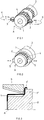
- FIG. 1 schematically shows the basic structure of a conventional impact rolling device for generating internal and external teeth on a cylindrical hollow body 1.
- the hollow body 1 is formed as a thin-walled pot, which on a profiled mandrel. 2 is postponed and processed from outside by means of arranged on a circular path K profile rollers 3 beating.
- the profile rollers 3 are thereby delivered radially against the axis A of the hollow body until the desired tread depth has been achieved on the hollow body 1.
- the profiles 4 are produced on the hollow body 1 at the front end with a straight end, while the profile ends tapering, with a radius corresponding to the shape of the circular path K ends. Now, if the profiles 4 must be formed close to a protruding radially outwardly of the hollow body 1 shoulder, so this process can be resp. do not use this device.
- FIG. 2 is now also schematically illustrated the basic structure of a device for machining cylindrical, thin-walled hollow bodies.
- a profiled mandrel 2 is used, on which the hollow body 1 to be profiled is placed.
- the hollow body 1 here now has an outwardly projecting shoulder 1 '.
- the profiles 4 should now be carried out from the front side to close to the shoulder.
- profiling tools 5 are now used, which can be delivered radially with respect to the axis A of the hollow body 1.
- the profiling tools 5 are driven by means of an eccentric drive (not shown for clarity) in a linear oscillating movement exactly radially to the axis A.
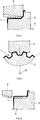
- FIG. 3 the longitudinal section through the mandrel 2 is shown with attached hollow body 1, wherein the profiling tool 5 is in the starting position for the processing of the shoulder 1 'of the hollow body 1.
- the hollow body 1 is pressed firmly against the mandrel 2 in the axial direction.
- the mandrel 2 has in particular a toothing resp. Longitudinal profiling on which the hollow body 1 rests with its inner side before machining.
- the mandrel 2 a shoulder 2 'on.
- the profiling tools 5 are now placed in the first process section in a sudden hammering action on the surface of the hollow body 1. Simultaneously with this oscillating movement of the profiling tools 5, these are now in the first process section radially against the axis A of the hollow body 1 to a previously defined resp. set depth, as shown in the longitudinal section FIG. 4 evident. At the end of this first process section, the profile is now formed in the region of the shoulder 1 ', while it is first preformed to the left to the front edge of the hollow body 1, but not yet fully formed.
- the profiling tools 5 may be operated at a speed of over 1000 beats per minute, for example even over 1500 beats per minute.
- the profiling tools 5 can be delivered in each case for each complete hollow body revolution in the radial direction in each case by at least about 0.1 mm until the desired tread depth is reached.
- FIG. 6 the longitudinal section through a hollow body 1 is analogous to FIG. 3 shown, in which case the profiling tool 5 is shown in its alternative starting position for processing.
- the profiling tool 5 is located axially in front of the end face of the hollow body 1, and is delivered radially in the predefined feed depth.
- the profiling tool 5 is now pushed axially in the direction of the shoulder 1 'of the hollow body 1 until reaching the desired profile length.
- the hollow body 1 is for example close to the end face of the mandrel 2, and the shoulder 1 'has against the shoulder 2' of the mandrel 2 on a small game.
- the material of the hollow body 1 during processing in the direction of this shoulder 2 'expand it is clear to the skilled person that this relative movement in the device itself by displacement of the hollow body 1, respectively. of the mandrel 2 relative to the profiling tool 5 can take place.
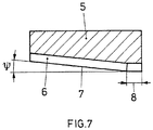
- FIG. 7 is still the longitudinal section of a profiling tool 5 shown, as it can be used for example for the claimed method.
- the profiling tool 5 is designed as a punch and has on its machining side 6 a cross-section to the profile 4 to be generated of the hollow body 1 corresponding shape, for example, a trapezoidal shape.
- the lower edge 7 of the machining side 6 is thereby arranged in relation to the axis A of the hollow body at an acute angle ⁇ . Depending on the shape and depth of the profile 4 to be produced, this angle is between 0.5 ° and 10 °.
- the lower edge 7 extends for example straight, but may also have a slight curvature.
- a calibration zone 8 is formed at the right end of the profiling tool 5 after FIG. 7 .
- the lower edge 7 is aligned parallel to the axis A of the hollow body 1, and the contour of the machining side 6 corresponds to the cross section of the profile to be produced on the outside of the hollow body 1.
- the lower edge 7 extends from the calibration zone 8 at an angle or possibly in an arc to the opposite end of the profiling tool 5. This angle resp. Arc corresponds to the contour of the preforming region of the profile 4 to be produced. It has been found that it can be advantageous if the length of the calibration zone 8 is only one Fraction of the total length of the profiling tool 5 corresponds.
- the axial feed of the hollow body 1 resp. of the mandrel 2 is to be tuned, for example, to the length of the calibration zone 8 and is when using two radially opposite profiling tools 5, for example, a maximum of twice this length in a full revolution of the hollow body.
- the stroke of the profiling tools 5 of the oscillating movement is dimensioned such that it is greater than the maximum radial infeed depth of the first method section.
- the profiling tools 5 arrive at each stroke once outside the contour of the surface of the hollow body 1.
- the hollow body respectively. the mandrel 2 in the same frequency as the oscillation of the profiling tool and synchronized to this movement, for example, intermittently rotated.
- the rotational movement is carried out, for example, exactly by a pitching step of the profiling, so that successive abrupt actions of the profiling tools 5 in adjacent profiles 4 of the hollow body 1 take place.
- a very precise and uniform profiling can be generated on the entire circumference of the hollow body 1.
- Very high production rates can be achieved by the already mentioned high rate of impact, which is particularly advantageous for mass production, for example in the automotive industry.
Landscapes
- Engineering & Computer Science (AREA)
- Mechanical Engineering (AREA)
- Forging (AREA)
- Turning (AREA)
- Shaping Metal By Deep-Drawing, Or The Like (AREA)
- Dental Prosthetics (AREA)
Description
- Die vorliegende Erfindung betrifft ein Verfahren nach dem Oberbegriff des Anspruchs 1, eine Vorrichtung zu seiner Durchführung, sowie seine Verwendung, siehe z.B. die
GB-A-1 324 090 - Die Herstellung einer axialen Profilierung eines dünnwandigen, zylindrischen Hohlteiles kann beispielsweise mittels Kaltwalzverfahren erfolgen. So sind Verfahren z.B. aus
US 5 355 706 bekannt, bei welchen Profilrollen als Werkzeuge auf einer Kreisbahn radial auf das Werkstück in schlagenden Eingriff gebracht werden und durch axialen Vorschub des Werkstückes gegenüber den Profilrollen die gewünschte Profilierung unter Verwendung eines verzahnten Dornwerkzeuges innen und aussen erzeugen. Allerdings werden bedingt durch die Kreisbahn der Profilrollen beim Eingriff in das Werkstück kreisbogenförmige Längskonturen erzeugt, welche abhängig von der Grösse der Bahndurchmesser einen grösseren oder kleineren Radius aufweisen, aber immer vorhanden sind. Ein Nachteil dieses Kaltumformverfahrens mittels Profilrollen besteht darin, dass die Verzahnung an einem zylindrischen Werkstück mit Schulter nicht dicht an diese Schulter heran ausgeführt werden kann. Bedingt durch die Kreisbahn der Profilrollen verbleibt zwischen dem Ende der Profilierung und der Schulter ein bestimmter Abschnitt auf dem Werkstück, welcher nicht bearbeitet werden kann. Die Aufgabe der vorliegenden Erfindung bestand nun darin, ein Verfahren und eine Vorrichtung zu finden, welche eine genaue Profilierung von dünnwandigen, zylindrischen Hohlkörpern mit einer definierten Profilgeometrie, auch bis dicht an einen Schulterbereich heran, erlauben. - Diese Aufgabe wird mit dem Verfahren mit den Merkmalen nach Anspruch 1 gelöst. Weitere Ausführungsformen ergeben sich aus den Merkmalen der weiteren Ansprüche 2 bis 9.
- Insbesondere wird beim beanspruchten Verfahren ein kaltumformendes Profilieren von zylindrischen, dünnwandigen Hohlteilen durchgeführt, mit im Wesentlichen parallel zur Längsachse des Hohlteiles verlaufenden Profilen, wobei radial zur Längsachse des Hohlteiles auf das Hohlteil von Aussen mindestens ein Profilierungswerkzeug schlagartig hämmernd zur Einwirkung gebracht wird, wobei das Profilierungswerkzeug jeweils in einer im Wesentlichen senkrechten Richtung oszillierend auf die Oberfläche des Hohlteils zur Einwirkung gebracht wird. Weiter wird das Profilierungswerkzeug bei gleich bleibender radialer Zustelltiefe axial relativ gegenüber dem Hohlteil verschoben, bis die gewünschte Profillänge erreicht ist. Damit kann in einem Arbeitsgang das Profil in seiner gesamten Länge vollständig erzeugt werden, wobei die gesamte Umformarbeit in eine Vielzahl von Einzelschritten aufgeteilt wird. Dadurch können die Umformkräfte jedes Einzelschrittes verhältnismässig klein gehalten werden. Dies führt zu einer hohen Genauigkeit des erzeugten Profils, sowohl als Innen- oder Aussenprofil, sowie zu einer hervorragenden Profilausformung. Insbesondere können mit dem Verfahren verhältnismässig kleine Profilradien erzeugt werden, was den tragenden Flankenanteil im Vergleich zu identischen Profildimensionen massgeblich vergrössert. Weiter kann dabei das Profilierungswerkzeug dank im Wesentlichen senkrechter oszillierender Bewegung in Bezug auf die Oberfläche des Hohlteils bis dicht an eine allfällige Schulter des Hohlteiles positioniert werden und damit eine Profilierung bis dicht an diese Schulter heran ausgeführt werden. D.h. dass das Profilierungswerkzeug praktisch keine Bewegung in axialer Richtung ausführt und damit auch keinen freien Bewegungsraum in axialer Richtung im Bearbeitungsbereich des Hohlteils benötigt.
- Beispielsweise wird vorgängig zur axialen Verschiebung das Profilierungswerkzeug radial zur Längsachse des Hohlteils bis zu einer vordefinierten Zustelltiefe zugestellt. Dadurch, dass das resp. die Profilierungswerkzeuge vor dem eigentlichen Bearbeitungsvorgang radial in einer entfernten Position vom Hohlteil angeordnet sind, kann das Hohlteil mit genügend freiem Raum in der Bearbeitungsvorrichtung angeordnet resp. mit einem Werkstückhalter verbunden werden.
- Zum Beispiel wird mindestens einmal ein Richtungswechsel der axialen Verschiebung zwischen Profilierungswerkzeug und Hohlteil ausgeführt, insbesondere nach dem Erreichen der gewünschten Profillänge zurück zur ursprünglichen relativen Ausgangsposition zwischen Profilierungswerkzeug und Hohlteil. Damit können sehr hohe Anforderungen an die Genauigkeit und Oberflächenbeschaffenheit der Profilierung erfüllt werden. Denkbar ist sogar ein mehrfaches achsparalleles hin und her verschieben des Hohlteiles bezüglich dem Profilierungswerkzeug, um die gewünschte Oberflächenqualität zu erreichen.
- Beispielsweise wird jeweils nach Abschluss der axialen relativen Verschiebung resp. Bewegung das Profilierungswerkzeug radial aus dem Profil des Hohlteiles herausgefahren. Damit lässt sich das fertig geformte Hohlteil einfach aus der Bearbeitungsvorrichtung entfernen und ein neues Rohteil einsetzen. Mit dem beanspruchten Verfahren kann zum Beispiel eine definierte Profilierung, wie beispielsweise eine Verzahnung mit definierter Teilung, erzeugt werden.
- Anspruchsgemäss ist die oszillierende Hubbewegung der Profilierungswerkzeuge grösser gewählt als die maximale radiale Eintauchtiefe der Profilierungswerkzeuge in das Hohlteil. Dabei wird das Hohlteil beispielsweise intermittierend, mit der oszillierenden Hubbewegung synchronisiert um seine Achse rotiert, zum Beispiel jeweils um den Teilungsabstand der zu erzeugenden Profilierung. Beispielsweise kann das Profilierungswerkzeug mit über 1000 Schlägen pro Minute, zum Beispiel mit über 1500 Schlägen pro Minute, betrieben werden. Damit können sehr hohe Produktionsraten erzielt werden, was gerade für die Massenproduktion in der Automobilindustrie von grossem Vorteil ist.
- Anspruchsgemäss wird das Hohlteil zur Bearbeitung auf einen profilierten Dorn aufgesetzt, welcher gegenüber dem Profilierungswerkzeug entlang der Längsachse verschiebbar angeordnet ist. Damit wird sowohl das Aussen- wie auch das Innenprofil des Hohlkörpers entsprechend den Vorgaben an die Formgebung schnell und besonders genau gefertigt.
- Beispielsweise reicht die Profilierung des Dorns von seinem freien Ende bis zu einer radial nach Aussen abstehenden Schulter und es wird ein Hohlteil aufgesetzt, welches topfartig ausgebildet ist und ebenfalls eine Schulter resp. einen Rand aufweist. Derartige Hohlteile finden beispielsweise im Getriebebau Anwendung, wie für die Übertragung von Rotation und Drehmoment in automatischen Getrieben. Dabei müssen häufig die Profile als exakte Innen- und Aussenverzahnung bis dicht an den nach Aussen abstehenden Rand des Hohlteiles ausgeführt resp. gefertigt werden.
- Beispielsweise wird das Profilierungswerkzeug für den ersten Verfahrensabschnitt im Bereich der Schulter des Dorns resp. im Bereich des Randes des Hohlteiles radial zur Einwirkung gebracht und im zweiten Verfahrensabschnitt wird der Dorn axial vom Profilierungswerkzeug weg verschoben. Dabei kann entweder das Profilierungswerkzeug oder das Hohlteil in der Maschine verschoben werden, um die axiale Relativbewegung zwischen Hohlteil und Profilierungswerkzeug zu erzeugen. Diese Bewegung wird zum Beispiel in einer solchen Länge ausgeführt, bis das Profilierungswerkzeug nicht mehr zur Einwirkung auf das Hohlteil gelangt. Diese Bewegung wird als ziehende Bewegung bezeichnet, da das Profilierungswerkzeug praktisch nach dem Einstechvorgang bis auf den Profilgrund relativ zum Hohlteil ziehend bewegt und damit die gesamte Länge der Profilierung erzeugt wird.
- Beispielsweise wird das Profilierungswerkzeug zuerst im Bereich des freien Endes des Hohlteiles resp. des Dornes radial zugestellt und danach wird der Dorn resp. das Hohlteil axial in Bezug auf das Profilierungswerkzeug zur Schulter resp. dem Rand hin verschoben, zum Beispiel bis das Profilierungswerkzeug dicht an die Schulter des Dorns resp. den Rand des Hohlteiles in Einwirkung steht. Auch hier kann selbstverständlich die relative Bewegung zwischen Profilierungswerkzeug und Hohlteil in der Maschine durch axiale Verschiebung des Hohlteiles bewerkstelligt werden. Diese Bewegung wird als stossende Bewegung bezeichnet, da das Profilierungswerkzeug primär das Profil gegen den Rand des Hohlteiles hin formt und fertig stellt. Dabei kann beispielsweise das Werkzeug ausserhalb des freien Endes auf die vordefinierte Zustelltiefe zugestellt werden und erst danach auf das Hohlteil zur Einwirkung gebracht werden. Beispielsweise werden jeweils mindestens zwei einander radial gegenüberliegend angeordnete Profilierungswerkzeuge eingesetzt, welche zum Beispiel miteinander in Bezug auf ihre radiale Zustellung und ihre Oszillationsbewegung synchronisiert angetrieben sind. Damit kann eine optimale Kraftverteilung und -einleitung gewährleistet werden. Beispielsweise wird das Profilierungswerkzeug radial in Bezug auf das Werkstück kontinuierlich oder in diskreten, einstellbaren Schritten zugestellt, bis die endgültige Profiltiefe des Hohlteiles erreicht ist.
- Weiter wird die Aufgabe durch eine Vorrichtung mit den Merkmalen nach Anspruch 10 gelöst.
- Weitere Ausführungsformen der Vorrichtung ergeben sich aus den Merkmalen der weiteren Ansprüche 11 bis 18.
- Anspruchsgemäss weist die Vorrichtung zur Durchführung des beanspruchten Verfahrens mindestens einen mit einem Exzenterantrieb wirkverbundenen Werkzeughalter für ein Profilierungswerkzeug, einen gegenüber dem Werkzeughalter entlang seiner Längsachse verschiebbar ausgebildeten Dorn resp. Werkstückhalter für ein Hohlteil, einen Antrieb zur Rotation des Dornes resp. Werkstückhalters um seine Längsachse, und mindestens ein als Stempel ausgebildetes Profilierungswerkzeug auf. Dabei weist der Stempel ein Arbeitsprofil auf, das der zu erzeugenden Profilform der Aussenseite des Hohlteils entspricht, wobei die Arbeitsprofilachse resp. Arbeitsoberfläche in einem spitzen Winkel zur Längsachse ausgerichtet ist, mit Ausnahme eines Bereiches der radial den kürzesten Abstand zur Oberfläche des Hohlkörpers aufweist, der als Kalibrierzone parallel zur Längsachse ausgerichtet ist. Damit greift jeweils die Kalibrierzone zuerst in die Oberfläche des Hohlkörpers ein, da diese Zone der Oberfläche des Hohlkörpers in Bearbeitungsrichtung des Stempels am nächsten liegt. Nach dem Eindringen der Kalibrierzone kann insbesondere bei ziehender Bearbeitung des Hohlkörpers jeweils auch der Rest Arbeitsoberfläche des Stempels in die Oberfläche eindringen und eine erste Vorverformung des Hohlkörpers ausführen. Im zweiten Verfahrensabschnitt, wenn der Stempel bei konstanter radialer Zustellung axial gegenüber dem Hohlkörper bewegt wird, brauch dann die Kalibrierzone lediglich noch die Endverformung des Profils vorzunehmen. Beispielsweise ist die Länge des Stempels resp. die Länge des Arbeitsprofils länger als die Länge des zu erzeugenden Profils im Hohlkörper. Damit wird beispielsweise bei der ziehenden Bearbeitung des Hohlkörpers bereits auf der gesamten Länge des Profils beim radialen Zustellen das Profil vorgeformt.
- Beispielsweise beträgt die Länge der Kalibrierzone nur einen Bruchteil der Gesamtlänge des Stempels res. der Länge des Arbeitsprofils. Diese Kalibrierzone ist letztlich für die Formgebung und Genauigkeit der Profilierung massgebend, da am Ende der radialen Zustellung nur noch diese Kalibrierzone mit dem Hohlteil in Kontakt steht.
- Zum Beispiel wird der Stempel aus einem hochfesten Werkstoff gefertigt sein resp. eine entsprechende
- Oberflächenbehandlung aufweisen, um eine möglichst lange Standzeit zu erreichen und damit eine hohe Genauigkeit der erstellten Profilierungen auch über einen längeren Herstellungszeitraum zu gewährleisten.
- Beispielsweise weist die Vorrichtung mindestens zwei, einander in Bezug auf die Längsachse des Hohlkörpers gegenüberliegend angeordnete Profilierungswerkzeuge auf. Damit wird eine optimale Krafteinleitung- und -verteilung auf das Hohlteil gewährleistet, und auch die Kräfte in der Vorrichtung selbst können optimal aufgenommen und verteilt werden. Denkbar sind natürlich auch andere Anordnungen, zum Beispiel jeweils symmetrische Anordnungen der Profilierungswerkzeuge.
- Ein Ausführungsbeispiel der vorliegenden Erfindung werden nachstehend anhand von Figuren noch näher erläutert. Es zeigen
-
Fig. 1 schematisch den prinzipiellen Aufbau einer herkömmlichen Schlagwalzvorrichtung mit auf einer Kreisbahn umlaufenden Profilierungsrollen; -
Fig. 2 schematisch den prinzipiellen Aufbau einer Vorrichtung zur Durchführung des Verfahrens; -
Fig. 3 den Längsschnitt durch einen auf einem Dorn aufgesetzten topfförmigen Hohlkörper vor der Bearbeitung mit einem Profilierungswerkzeug; -
Fig. 4 den Längsschnitt vonFigur 3 nach dem ersten Verfahrensabschnitt der Verfahrens; -
Fig. 5 den Querschnitt durch den Bearbeitungsbereich des Längsschnittes vonFigur 4 ; -
Fig. 6 den Längsschnitt durch einen auf einem Dorn aufgesetzten topfförmigen Hohlkörper vor der alternativen Bearbeitung mit einem Profilierungswerkzeug; und -
Fig. 7 den Längsschnitt eines Profilierungswerkzeuges. -
Figur 1 zeigt schematisch den prinzipiellen Aufbau einer herkömmlichen Schlagwalzvorrichtung zur Erzeugung von Innen- und Aussenverzahnung an einem zylindrischen Hohlkörper 1. Der Hohlkörper 1 ist dabei als dünnwandiger Topf ausgebildet, der auf einem profilierten Dorn 2 aufgeschoben ist und von Aussen mittels auf einer Kreisbahn K angeordneten Profilrollen 3 schlagend bearbeitet wird. Die Profilrollen 3 werden dabei radial gegen die Achse A des Hohlkörpers zugestellt, bis die gewünschte Profiltiefe am Hohlkörper 1 erreicht worden ist. Aus dieser Darstellung ist ersichtlich, dass die Profile 4 am Hohlkörper 1 stirnseitig mit einem geraden Abschluss erzeugt werden, während die Profilenden zulaufend, mit einem Radius entsprechend der Form der Kreisbahn K enden. Wenn nun die Profile 4 bis dicht an eine vom Hohlkörper 1 radial nach Aussen abstehende Schulter ausgebildet sein müssen, lässt sich damit dieses Verfahren resp. diese Vorrichtung nicht einsetzen. - In
Figur 2 ist nun ebenfalls schematisch der prinzipielle Aufbau einer Vorrichtung zur Bearbeitung von zylindrischen, dünnwandigen Hohlkörpern dargestellt. Hier wird ebenfalls ein profilierter Dorn 2 eingesetzt, auf welchem der mit einer Profilierung zu versehende Hohlkörper 1 aufgesetzt ist. Der Hohlkörper 1 weist hier nun eine nach Aussen abragende Schulter 1' auf. Die Profile 4 sollen nun von der Stirnseite her bis dicht an die Schulter ausgeführt werden. Hierfür werden nun Profilierungswerkzeuge 5 eingesetzt, welcher radial in Bezug auf die Achse A des Hohlkörpers 1 zugestellt werden können. Die Profilierungswerkzeuge 5 werden mittels eines Exzenterantriebs (der Übersicht halber nicht dargestellt) in eine lineare oszillierende Bewegung exakt radial zur Achse A angetrieben. - In
Figur 3 ist der Längsschnitt durch den Dorn 2 mit aufgesetztem Hohlkörper 1 dargestellt, wobei sich das Profilierungswerkzeug 5 in der Ausgangslage für die Bearbeitung von der Schulter 1' des Hohlkörpers 1 befindet. Der Hohlkörper 1 ist dabei in axialer Richtung fest gegen den Dorn 2 angedrückt. Der Dorn 2 weist insbesondere eine Verzahnung resp. Längsprofilierung auf, auf welche der Hohlkörper 1 vor der Bearbeitung mit seiner Innenseite aufliegt. Weiter weist auch der Dorn 2 eine Schulter 2' auf. - Die Profilierungswerkzeuge 5 werden nun im ersten Verfahrensabschnitt in eine schlagartige hämmernde Einwirkung auf die Oberfläche des Hohlkörpers 1 gebracht. Gleichzeitig zu dieser oszillierenden Bewegung der Profilierungswerkzeuge 5 werden diese nun im ersten Verfahrensabschnitt radial gegen die Achse A des Hohlkörpers 1 bis in eine vorgängig definierte resp. eingestellte Tiefe zugestellt, wie aus dem Längsschnitt nach
Figur 4 hervorgeht. Am Ende dieses ersten Verfahrensabschnittes ist damit nun das Profil im Bereich der Schulter 1' geformt, während es nach links zur Stirnkante des Hohlkörpers 1 erst vorgeformt, aber noch nicht fertig ausgeformt ist. - Durch eine axiale Relativverschiebung des Hohlkörpers 1 in Bezug auf das Profilierungswerkzeug 5 im zweiten Verfahrensabschnitt, bei welchem das Profilierungswerkzeug 5 bei konstanter Zustelltiefe quasi aus den Hohlkörper 1 herausgezogen wird, wird das Profil 4 nun auf seiner gesamten Länge fertig geformt. In
Figur 5 ist im Querschnitt das Profilierungswerkzeug 5 in seiner definierten Zustelltiefe in der untersten Bearbeitungsresp. Eingriffslage im Hohlkörper 1 dargestellt. Hier ist besonders deutlich das im Querschnitt fertig geformte Profil 4 des Hohlkörpers 1 ersichtlich. - Typischerweise können die Profilierungswerkzeuge 5 mit einer Schlaggeschwindigkeit von über 1000 Schlägen pro Minute betrieben werden, beispielsweise sogar mit über 1500 Schlägen pro Minute. Dabei können die Profilierungswerkzeuge 5 beispielsweise bei jeder vollständigen Hohlkörperumdrehung in radialer Richtung jeweils um mindestens etwa 0.1 mm zugestellt werden, bis die gewünschte Profiltiefe erreicht ist.
- In
Figur 6 ist der Längsschnitt durch einen Hohlkörper 1 analog zuFigur 3 dargestellt, wobei hier das Profilierungswerkzeug 5 in seiner alternativen Ausgangslage für die Bearbeitung dargestellt ist. Das Profilierungswerkzeug 5 befindet sich axial gesehen vor der Stirnseite des Hohlkörpers 1, und ist radial in der vordefinierten Zustelltiefe zugestellt. Für die eigentliche Bearbeitung des Hohlkörpers 1 wird das Profilierungswerkzeug 5 nun axial in Richtung der Schulter 1' des Hohlkörpers 1 bis zum Erreichen der gewünschten Profillänge hinein geschoben. Der Hohlkörper 1 liegt dabei beispielsweise dicht an die Stirnfläche des Dorns 2 an, und die Schulter 1' weist gegenüber der Schulter 2' des Dorns 2 ein kleines Spiel auf. Damit kann sich das Material des Hohlkörpers 1 bei der Bearbeitung in Richtung dieser Schulter 2' ausdehnen. Es ist für den Fachmann klar, dass diese Relativbewegung in der Vorrichtung selbst auch durch Verschiebung des Hohlkörpers 1 resp. des Dorns 2 gegenüber dem Profilierungswerkzeug 5 erfolgen kann. - In
Figur 7 ist noch der Längsschnitt eines Profilierungswerkzeuges 5 dargestellt, wie es beispielsweise für das beanspruchte verfahren eingesetzt werden kann. Das Profilierungswerkzeug 5 ist als Stempel ausgebildet und weist an seiner Bearbeitungsseite 6 eine im Querschnitt dem zu erzeugenden Profil 4 des Hohlkörpers 1 entsprechende Form auf, beispielsweise eine Trapezform. Die untere Kante 7 der Bearbeitungsseite 6 wird dabei in Bezug zur Achse A des Hohlkörpers in einem spitzen Winkel ϕ angeordnet. Dieser Winkel beträgt je nach Form und Tiefe des zu erzeugenden Profils 4 zwischen 0,5° und 10°. - Die untere Kante 7 verläuft dabei beispielsweise gerade, kann aber auch eine leichte Krümmung aufweisen. Am rechten Ende des Profilierungswerkzeuges 5 nach
Figur 7 ist eine Kalibrierzone 8 ausgebildet. Im Bereich dieser Kalibrierzone 8 ist die untere Kante 7 parallel zur Achse A des Hohlkörpers 1 ausgerichtet, und die Kontur der Bearbeitungsseite 6 entspricht dem Querschnitt des auf der Aussenseite des Hohlkörpers 1 zu erzeugenden Profils. Die untere Kante 7 verläuft von der Kalibrierzone 8 in einem Winkel oder ggf. in einem Bogen zum gegenüberliegenden Ende des Profilierungswerkzeuges 5. Dieser Winkel resp. Bogen entspricht der Kontur des Vorformungsbereichs des zu erzeugenden Profils 4. Es hat sich gezeigt, dass es von Vorteil sein kann wenn die Länge der Kalibrierzone 8 nur einem Bruchteil der Gesamtlänge des Profilierungswerkzeuges 5 entspricht. - Der Axialvorschub des Hohlkörpers 1 resp. des Dorns 2 ist beispielsweise auf die Länge der Kalibrierzone 8 abzustimmen und beträgt beim Einsatz von zwei einander radial gegenüberliegenden Profilierungswerkzeugen 5 zum Beispiel maximal das Doppelte dieser Länge bei einer vollen Umdrehung des Hohlkörpers 1.
- Der Hub der Profilierungswerkzeuge 5 der oszillierenden Bewegung wird derart bemessen, dass er grösser ist als die maximale radiale Zustelltiefe des ersten Verfahrensabschnittes. Damit gelangen die Profilierungswerkzeuge 5 bei jedem Hub einmal ausserhalb der Kontur der Oberfläche des Hohlkörpers 1. Sodann wird der Hohlkörper 1 resp. der Dorn 2 in der gleichen Frequenz wie die Oszillation des Profilierungswerkzeuges und synchronisiert zu dieser Bewegung beispielsweise intermittierend rotiert werden. Dabei wird die Rotationsbewegung jeweils beispielsweise genau um einen Teilungsschritt der Profilierung ausgeführt, so dass jeweils aufeinander folgende schlagartige Einwirkungen der Profilierungswerkzeuge 5 in benachbarten Profilen 4 des Hohlkörpers 1 erfolgen. Damit kann eine sehr präzise und gleichförmige Profilierung am gesamten Umfang des Hohlkörpers 1 erzeugt werden.
- Durch die bereits erwähnte hohe Schlagzahl können sehr hohe Produktionsraten erzielt werden, was besonders für die Massenproduktion beispielsweise in der Automobilindustrie von grossem Vorteil ist.
Claims (19)
- Verfahren zum kaltumformenden Profilieren von zylindrischen, dünnwandigen Hohlteilen (1) zur Erzeugung von Innen- und Aussenverzahnungen an den Hohlteilen mit im Wesentlichen parallel zur Längsachse (A) des Hohlteiles (1) verlaufenden Profilen, dadurch gekennzeichnet, dass:- das Hohlteil (1) zur Bearbeitung auf einen prafilierten Dom aufgesetzt wird, welcher gegenüber dem Profilierungswerkzeug (5) entlang der Längsachse (A) verschiebbar angeordnet ist,- radial zur Längsachse (A) des Hohlteiles (1) auf das Hohlteil (1) von aussen mindestens ein mit einem Exzenterantrieb wirkverbundenes Profilierungswerkzeug (5) schlagartig hämmernd zur Einwirkung gebracht wird,- das Profilierungswerkzeug (5) jeweils einzig in einer im Wesentlichen senkrechten Richtung oszillierend auf die Oberfläche des Hohlteiles (1) zur Einwirkung gebracht wird- die oszillierenden Hubbewegung des Profilierungswerkzeugs (5) grösser gewählt ist als die maximale radiale Eintauchtiefe des Profilierungswerkzeugs (5) in das Hohlteil (1),- das Hohlteil (1) intermittierend, mit der oszillierenden Hubbewegung synchronisiert um seine Längsachse (A) rotiert wird, insbesondere jeweils um den Teilungsabstand der zu erzeugenden Profilierung, und- das Profilierungswerkzeug (5) bei gleich bleibender radialer Zustelltiefe axial relativ gegenüber dem Hohlteil (1) verschoben wird, bis die gewünschte Profillänge erreicht ist,wobei das Profilierungswerkzeug (5) als Stempel mit einer Bearbeitungsseite (6) ausgebildet ist und an seiner Bearbeitungsseite (6) eine im Querschnitt dem zu erzeugenden Profil (4) des Hohlkörpers (1) entsprechende Form aufweist, und
wobei die Bearbeitungsseite (6) eine untere Kante (7) aufweist, die, in einem Längsschnitt, in Bezug zur Längsachse (A) in einem spitzen Winkel angeordnet ist, wobei aber an einem Ende des Profilierungswerkzeuges (5) eine Kalibrierzone (8) ausgebildet ist und im Bereich der Kalibrierzone (8) die untere Kante (7), in einem Längsschnitt, parallel zur Längsachse (A) ausgerichtet ist und im Querschnitt die Kontur der Bearbeitungsseite (6) dem auf der Aussenseite des Hohlkörpers (1) zu erzeugenden Profil entspricht, und wobei die untere Kante (7) in der Kalibrierzone (8) radial den kürzesten Abstand zur Oberfläche des Hohlkörpers (1) aufweist. - Verfahren nach Anspruch 1, dadurch gekenntzeichnet, dass vorgängig zur axialen Verschiebung das Profilierungswerkzeug (5) radial zur Längsachse des Hohlteiles (1) bis zu einer vordefinierten Zustelltiefe zugestellt wird.
- Verfahren nach Anspruch 1 oder 2, dadurch gekennzeichnet, dass mindestens einmal ein Richtungswechsel der axialen Verschiebung zwischen Profilierungswerkzeug (5) und Hohlteil (1) ausgeführt wird, beispielsweise nach dem Erreichen der gewünschten Profillänge zurück zur ursprünglichen Ausgangsposition.
- Verfahren nach einem der Ansprüche 1 bis 3, dadurch gekennzeichnet, dass jeweils nach Abschluss der axialen relativen Verschiebung das Profilierungswerkzeug (5) radial aus dem Profil (4) des Hohlteiles (1) herausgefahren wird.
- Verfahren nach einem der Ansprüche 1 bis 4, dadurch gekennzeichnet, dass die Profilierung des Dorns (2) von seinem freien Ende bis zu einer radial nach aussen abstehenden Schulter (2') reicht und ein Hohlteil (1) aufgesetzt wird, welches topfartig ausgebildet ist und einen Rand oder eine Schulter (1') aufweist.
- Verfahren nach Anspruch 5, dadurch gekennzeichnet, dass das Profilierungswerkzeug (5) zuerst im Bereich der Schulter (2') des Dorns (2) resp. im Bereich des Randes (1') des Hohlteiles (1) radial zur Einwirkung gebracht wird und danach der Dorn (2) resp. das Hohlteil (1) axial in Bezug auf das Profilierungswerkzeug (5) von der Schulter (2') resp. dem Rand (1') weg verschoben wird, beispielsweise das Profilierungswerkzeug (5) nicht mehr zur Einwirkung auf das Hohlteil (1) gelangt.
- Verfahren nach Anspruch 5, dadurch gekennzeichnet, dass das Profilierungswerkzeug (5) im Bereich des freien Endes des Hohlteiles (1) resp. des Dornes (2) radial bis zu einer definierten Zustelltiefe zugestellt wird und danach der Dorn (2) axial in Bezug auf das Profilierungswerkzeug (5) verschoben wird, beispielsweise bis das Profilierungswerkzeug (5) dicht an die Schulter (2') des Dorns (2) resp. den Rand (1') des Hohlteiles (1) in Einwirkung steht.
- Verfahren nach einem der Ansprüche 1 bis 7, dadurch gekennzeichnet, dass jeweils mindestens zwei einander radial gegenüberliegend angeordnete Profilierungswerkzeuge (5) eingesetzt werden, beispielsweise miteinander in Bezug auf ihre radiale Zustellung und ihre Oszillationsbewegung synchronisiert angetrieben.
- Verfahren nach einem der Ansprüche 1 bis 8, dadurch gekennzeichnet, dass das Profilierungswerkzeug (5) radial in Bezug auf den Hohlkörper (1) kontinuierlich oder in diskreten, einstellbaren Schritten zugestellt wird, bis die endgültige Tiefe des Profils (4) des Hohlteiles (1) erreicht ist.
- Vorrichtung zur Durchführung des Verfahrens nach einem der Ansprüche 1 bis 9, mit- einem Exzenterantrieb und- mindestens einem zur Erzeugung der oszillierenden Hubbewegung des Profilierungswerkzeugs (5) mit dem Exzenterantrieb wirkverbundenen Profilierungswerkzeug (5) sowie- einem gegenüber dem Profilierungswerkzeug (5) entlang seiner Längsachse (A) verschiebbar ausgebildeten Werkstückhalter in Form eines profilierten Dorns (2) für ein Hohlteil (1),- einem Antrieb zur intermittierenden und mit der oszillierenden Hubbewegung synchronisierten Rotation des Dorns (2) um seine Längsachse (A),wobei- das Profilierungswerkzeug (5) als Stempel mit einer Bearbeitungsseite (6) ausgebildet ist und an seiner Bearbeilungsseite (6) eine im Querschnitt dem zu erzeugenden Profil (4) des Hohlkörpers (1) entsprechende Form aufweist,- die Bearbeitungsseite (6) eine untere Kante (7) aufweist, die, in einem Längsschnitt, in Bezug zur Längsachse (A) in einem spitzen Winkel angeordnet ist, wobei aber an einem Ende des Profilierungswerkzeuges (5) eine Kalibrierzone (8) ausgebildet ist und im Bereich der Kalibrierzone (8) die untere Kante (7), in einem Längsschnitt, parallel zur Längsachse (A) ausgerichtet ist und im Querschnitt die Kontur der Bearbeitungszone (6) dem auf der Aussenseite des Hohlkörpers (1) zu erzeugenden Profil entspricht, und wobei die untere Kante (7) in der Kalibrierzone (8) radial den kürzesten Abstand zur Längsachse (A) aufweist.
- Vorrichtung nach Anspruch 10 , dadurch gekennzeichnet, dass die Länge des Stempels (5) resp. die Länge des Arbeitsprofils länger ist als die Länge des zu erzeugenden Profils (4) im Hohlkörper (1).
- Vorrichtung nach Anspruch 10 oder 11, dadurch gekennzeichnet, dass die Länge der Kalibrierzone (8) nur einen Bruchteil der Gesamtlänge des Stempels (5) resp. der Länge des Arbeitsprofils beträgt.
- Vorrichtung nach einem der Ansprüche 10 bis 12, dadurch gekennzeichnet, dass sie mindestens zwei, einander in Bezug auf die Längsachse (A) des Hohlkörpers (1) gegenüberliegend angeordnete Profilierungswerkzeuge (5) aufweist.
- Vorrichtung nach Anspruch 10, dadurch gekennzeichnet, dass die Profilierung des Dorns (2) von seinem freien Ende bis zu einer radial nach aussen abstehenden Schulter (2') reicht
- Vorrichtung nach Anspruch 14, dadurch gekennzeichnet, dass der Dorn (2) dazu geeignet ist, dass auf ihn ein Hohlteil (1) aufgesetzt wird, welches topfartig ausgebildet ist und einen Rand oder eine Schulter (1') aufweist.
- Vorrichtung nach Anspruch 10, dadurch gekennzeichnet, dass der spitze Winkel je nach Form und Tiefe des zu erzeugenden Profils (4) zwischen 0,5° und 10° beträgt.
- Vorrichtung nach Anspruch 10, dadurch gekennzeichnet, dass die untere Kante (7) von der Kalibrierzone (8) in einem Winkel oder Bogen zum gegenüberliegenden Ende des Profilierungswerkzeuges (5) verläuft.
- Vorrichtung nach Anspruch 17, dadurch gekennzeichnet, dass dieser Winkel resp. Bogen der Kontur eines Vorformungsbereichs für das zu erzeugenden Profil (4) entspricht.
- Verwendung eines Verfahrens gemäss Anspruch 5 oder einer Vorrichtung gemäss Anspruch 14 zum kaltumformenden Profilieren von zylindrischen, dünnwandigen Hohlteilen (1) zur Erzeugung von Innen- und Aussenverzahnungen an den Hohlteilen mit im Wesentlichen parallel zur Längsachse (A) des Hohlteiles (1) verlaufenden Profilen, wobei die Hohlteile (1) topfartig ausgebildet sind und eine Schulter resp.einen Rand aufweisen und solche Hohlteile sind, die im Getriebebau Anwendung finden, für die Übertragung von Rotation und Drehmoment in automatischen Getrieben.
Applications Claiming Priority (1)
| Application Number | Priority Date | Filing Date | Title |
|---|---|---|---|
| PCT/CH2005/000406 WO2007009267A1 (de) | 2005-07-15 | 2005-07-15 | Verfahren zur erzeugung von innen- und aussenverzahnungen an dünnwandigen, zylindrischen hohlteilen |
Publications (2)
| Publication Number | Publication Date |
|---|---|
| EP1915225A1 EP1915225A1 (de) | 2008-04-30 |
| EP1915225B1 true EP1915225B1 (de) | 2017-11-01 |
Family
ID=35735096
Family Applications (1)
| Application Number | Title | Priority Date | Filing Date |
|---|---|---|---|
| EP05758521.8A Expired - Lifetime EP1915225B1 (de) | 2005-07-15 | 2005-07-15 | Verfahren zur erzeugung von innen- und aussenverzahnungen an dünnwandigen, zylindrischen hohlteilen |
Country Status (8)
| Country | Link |
|---|---|
| US (1) | US8117884B2 (de) |
| EP (1) | EP1915225B1 (de) |
| JP (1) | JP4873661B2 (de) |
| KR (1) | KR101292287B1 (de) |
| CN (1) | CN101198425B (de) |
| CA (1) | CA2615220C (de) |
| ES (1) | ES2676420T3 (de) |
| WO (1) | WO2007009267A1 (de) |
Families Citing this family (18)
| Publication number | Priority date | Publication date | Assignee | Title |
|---|---|---|---|---|
| CH706436A1 (de) * | 2012-04-25 | 2013-10-31 | Grob Ernst Fa | Verfahren und Vorrichtung zur Herstellung von mit einer innenliegenden Laufradverzahnung versehenen dickwandigen Hohlrädern. |
| CN102990472B (zh) * | 2012-11-17 | 2016-06-22 | 山东省青岛生建机械厂 | 高速间歇分度机构 |
| AT514020B1 (de) * | 2013-03-07 | 2015-05-15 | Steyr Mannlicher Gmbh | Verfahren zum Herstellen eines Laufs mit Laufflutungen |
| KR102282551B1 (ko) | 2013-09-04 | 2021-07-27 | 이데미쓰 고산 가부시키가이샤 | 카바졸 유도체, 이것을 이용한 유기 전기발광 소자용 재료, 및 이것을 이용한 유기 전기발광 소자 및 전자 기기 |
| EP3060825B1 (de) * | 2013-10-23 | 2021-02-24 | Ernst Grob AG | Verbundbremsscheibe sowie verfahren und vorrichtung zur herstellung derselben |
| EP2982456B1 (de) * | 2014-08-05 | 2016-11-30 | Feintool International Holding AG | Vorrichtung und Verfahren zum Herstellen von für Synchronisationssysteme geeignete mit Zähnen bzw. Zahnabschnitten versehene Kupplungskörper |
| CN105436327B (zh) * | 2014-08-12 | 2018-02-02 | 博世华域转向系统(烟台)有限公司 | 一种转向管柱的下转向轴花键用铆压装置 |
| US9890808B2 (en) | 2015-04-22 | 2018-02-13 | American Axle & Manufacturing, Inc. | Telescoping propshaft |
| DE102016103946A1 (de) * | 2016-03-04 | 2017-09-07 | Leifeld Metal Spinning Ag | Verfahren und Vorrichtung zum Umformen eines Werkstücks mit trommelförmiger Umfangswand |
| US10837072B2 (en) * | 2016-08-29 | 2020-11-17 | Magna Powertrain Inc. | Splined power transmission components made using heat-assisted calibration process and method of forming such splined power transmission components |
| CN108246917B (zh) * | 2018-02-05 | 2020-02-07 | 吉林大学 | 一种离合器毂齿形辊压成形装置及加工工艺 |
| CH714660A1 (de) * | 2018-02-16 | 2019-08-30 | Grob Ernst Fa | Vorrichtung und Verfahren zur Herstellung eines Hohlrades mit Innen- und Aussenverzahnung sowie Hohlrad. |
| CH714772A1 (de) * | 2018-11-15 | 2019-09-13 | Grob Ernst Fa | Vorrichtung und Verfahren zum kaltumformenden Profilieren von Werkstücken. |
| EP3670018A1 (de) * | 2018-12-20 | 2020-06-24 | Leifeld Metal Spinning AG | Verfahren und umformanlage zum herstellen eines trommelförmigen getriebeteiles |
| EP3711707B1 (de) * | 2019-03-21 | 2022-01-19 | SIRONA Dental Systems GmbH | Relative ausrichtung zwischen gekoppelten bearbeitungswerkzeugen und rohkörpern |
| CN111014392B (zh) * | 2019-12-06 | 2021-08-27 | 吉林大学 | 一种离合器毂齿形轴向多点辊压成形装置 |
| CN111842754B (zh) * | 2020-07-08 | 2021-08-27 | 西安交通大学 | 圆弧齿底非渐开线齿形四锤头渐进径向锻造装置及工艺 |
| CH718706A1 (de) | 2021-06-04 | 2022-12-15 | Grob Ernst Fa | Vorrichtung und Verfahren zum kaltumformenden Profilieren von Werkstücken. |
Family Cites Families (9)
| Publication number | Priority date | Publication date | Assignee | Title |
|---|---|---|---|---|
| US1324090A (en) * | 1915-10-19 | 1919-12-09 | Lorillard Co P | Bale-band tightener. |
| DE1280198B (de) * | 1961-07-07 | 1968-10-17 | Grob Ernst Fa | Verfahren zum spanlosen Profilieren, vorzugsweise Verzahnen, von zylindrischen metallischen Werkstuecken und Vorrichtung zur Durchfuehrung des Verfahrens |
| US3352138A (en) * | 1965-10-23 | 1967-11-14 | Barber Colman Co | Tool for forming toothed parts |
| DE2401671A1 (de) * | 1974-01-15 | 1975-07-24 | Rueggeberg August Fa | Verfahren zur herstellung einer feile aus einem duennwandigen rohr |
| JP3089369B2 (ja) * | 1992-02-04 | 2000-09-18 | 本田技研工業株式会社 | スナップリング溝を有するスプライン付きカップ状製品の成形装置 |
| JPH0679390A (ja) * | 1992-09-04 | 1994-03-22 | Mitsubishi Heavy Ind Ltd | 棒状物の鍛造方法 |
| JPH07265990A (ja) * | 1994-03-28 | 1995-10-17 | Mazda Motor Corp | 円筒部品成形方法および成形装置 |
| JP3281175B2 (ja) * | 1994-04-18 | 2002-05-13 | 株式会社東芝 | プレス成形装置 |
| FR2755042B1 (fr) * | 1996-10-24 | 1998-12-24 | Lemforder Nacam Sa | Procede d'obtention de cannelures sur un arbre |
-
2005
- 2005-07-15 CA CA2615220A patent/CA2615220C/en not_active Expired - Fee Related
- 2005-07-15 WO PCT/CH2005/000406 patent/WO2007009267A1/de not_active Ceased
- 2005-07-15 JP JP2008520686A patent/JP4873661B2/ja not_active Expired - Fee Related
- 2005-07-15 EP EP05758521.8A patent/EP1915225B1/de not_active Expired - Lifetime
- 2005-07-15 KR KR1020087002571A patent/KR101292287B1/ko not_active Expired - Fee Related
- 2005-07-15 US US11/994,376 patent/US8117884B2/en active Active
- 2005-07-15 ES ES05758521.8T patent/ES2676420T3/es not_active Expired - Lifetime
- 2005-07-15 CN CN200580050082XA patent/CN101198425B/zh not_active Expired - Fee Related
Non-Patent Citations (1)
| Title |
|---|
| None * |
Also Published As
| Publication number | Publication date |
|---|---|
| KR101292287B1 (ko) | 2013-08-01 |
| US8117884B2 (en) | 2012-02-21 |
| US20100126020A1 (en) | 2010-05-27 |
| CN101198425A (zh) | 2008-06-11 |
| CN101198425B (zh) | 2011-06-08 |
| ES2676420T3 (es) | 2018-07-19 |
| JP4873661B2 (ja) | 2012-02-08 |
| JP2009500179A (ja) | 2009-01-08 |
| CA2615220C (en) | 2013-01-08 |
| CA2615220A1 (en) | 2007-01-25 |
| KR20080030071A (ko) | 2008-04-03 |
| EP1915225A1 (de) | 2008-04-30 |
| WO2007009267A1 (de) | 2007-01-25 |
Similar Documents
| Publication | Publication Date | Title |
|---|---|---|
| EP1915225B1 (de) | Verfahren zur erzeugung von innen- und aussenverzahnungen an dünnwandigen, zylindrischen hohlteilen | |
| DE102012017525B4 (de) | Verfahren zur umformenden Herstellung eines Zahnrads mit Außenverzahnung, sowie nach diesem Verfahren herstellbares Zahnrad mit Außenverzahnung | |
| EP0921879B1 (de) | Verfahren und vorrichtung zur herstellung eines aussen verzahnten getriebeteiles | |
| EP1629919A2 (de) | Werkzeug und Verwendung desselben zur Herstellung von Gewinden | |
| DE102006026992B4 (de) | Verfahren zur Erzeugung eines Gewindes in wenigstens zwei Arbeitsschritten | |
| EP0955110B1 (de) | Verfahren zum Drückwalzen und Drückwalzvorrichtung | |
| DE102013112123B4 (de) | Metallhülse und Verfahren zu deren Herstellung | |
| EP2794167B1 (de) | Kombinationswerkzeug und verfahren zur herstellung einer oberflächenstruktur mit hinterschnitten in einer oberfläche eines werkstücks | |
| EP0313985A2 (de) | Verfahren zur Herstellung einer Nockenwelle | |
| DE19723073C2 (de) | Verfahren zur Herstellung eines rotationssymmetrischen Werkstücks | |
| DE3879712T2 (de) | Verfahren zur bearbeitung eines laenglichen werkstueckes und vorrichtung dazu. | |
| DE102011102288B4 (de) | Vorrichtung und Verfahren zur Herstellung eines Stirnrads mit einer Schrägverzahnung | |
| EP2841218B1 (de) | Vorrichtung und verfahren zur herstellung von mit einer innenliegenden laufradverzahnung versehenen dickwandigen hohlrädern | |
| EP3670018A1 (de) | Verfahren und umformanlage zum herstellen eines trommelförmigen getriebeteiles | |
| EP3246104B1 (de) | Verfahren und vorrichtung zum herstellen eines umformteils | |
| EP0808678A1 (de) | Verfahren und Vorrichtung zum Herstellen einer Poly-V-Scheibe | |
| DE102017116895A1 (de) | Verfahren und Vorrichtung zur Herstellung einer Verzahnung an einem zylindrischen Werkstück | |
| DE19629738C2 (de) | Verfahren zum Herstellen rotationssymmetrischer Körper mit Nabe | |
| DE19954210B4 (de) | Rundknetmaschine | |
| DE4321779B4 (de) | Verfahren zur Herstellung eines Starterkranz-Zahnrads aus Blech und nach dem Verfahren hergestelltes Starterkranz-Zahnrad | |
| DE102009058178B4 (de) | Verfahren und Werkzeug zur Oberflächenbehandlung | |
| EP1713600A1 (de) | Vorrichtung und verfahren zur erzeugung von verzahnungsartigen profilierungen von werkstücken | |
| DE102011011886B4 (de) | Verfahren zum Verdichten der Oberfläche von Sintermetallbauteilen | |
| DE102017212054A1 (de) | Verfahren zur Herstellung eines Schneidkopfes sowie Schneidkopf | |
| EP1646461A1 (de) | Verfahren und vorrichtung zur bearbeitung von randbereichen von zylindrischen hohlkörpern |
Legal Events
| Date | Code | Title | Description |
|---|---|---|---|
| PUAI | Public reference made under article 153(3) epc to a published international application that has entered the european phase |
Free format text: ORIGINAL CODE: 0009012 |
|
| 17P | Request for examination filed |
Effective date: 20070601 |
|
| AK | Designated contracting states |
Kind code of ref document: A1 Designated state(s): AT BE BG CH CY CZ DE DK EE ES FI FR GB GR HU IE IS IT LI LT LU LV MC NL PL PT RO SE SI SK TR |
|
| 17Q | First examination report despatched |
Effective date: 20080520 |
|
| DAX | Request for extension of the european patent (deleted) | ||
| GRAP | Despatch of communication of intention to grant a patent |
Free format text: ORIGINAL CODE: EPIDOSNIGR1 |
|
| STAA | Information on the status of an ep patent application or granted ep patent |
Free format text: STATUS: GRANT OF PATENT IS INTENDED |
|
| INTG | Intention to grant announced |
Effective date: 20161125 |
|
| GRAJ | Information related to disapproval of communication of intention to grant by the applicant or resumption of examination proceedings by the epo deleted |
Free format text: ORIGINAL CODE: EPIDOSDIGR1 |
|
| STAA | Information on the status of an ep patent application or granted ep patent |
Free format text: STATUS: EXAMINATION IS IN PROGRESS |
|
| INTC | Intention to grant announced (deleted) | ||
| GRAP | Despatch of communication of intention to grant a patent |
Free format text: ORIGINAL CODE: EPIDOSNIGR1 |
|
| STAA | Information on the status of an ep patent application or granted ep patent |
Free format text: STATUS: GRANT OF PATENT IS INTENDED |
|
| INTG | Intention to grant announced |
Effective date: 20170606 |
|
| GRAS | Grant fee paid |
Free format text: ORIGINAL CODE: EPIDOSNIGR3 |
|
| GRAA | (expected) grant |
Free format text: ORIGINAL CODE: 0009210 |
|
| STAA | Information on the status of an ep patent application or granted ep patent |
Free format text: STATUS: THE PATENT HAS BEEN GRANTED |
|
| AK | Designated contracting states |
Kind code of ref document: B1 Designated state(s): AT BE BG CH CY CZ DE DK EE ES FI FR GB GR HU IE IS IT LI LT LU LV MC NL PL PT RO SE SI SK TR |
|
| REG | Reference to a national code |
Ref country code: GB Ref legal event code: FG4D Free format text: NOT ENGLISH |
|
| REG | Reference to a national code |
Ref country code: CH Ref legal event code: EP Ref country code: AT Ref legal event code: REF Ref document number: 941554 Country of ref document: AT Kind code of ref document: T Effective date: 20171115 |
|
| REG | Reference to a national code |
Ref country code: IE Ref legal event code: FG4D Free format text: LANGUAGE OF EP DOCUMENT: GERMAN |
|
| REG | Reference to a national code |
Ref country code: DE Ref legal event code: R096 Ref document number: 502005015736 Country of ref document: DE |
|
| REG | Reference to a national code |
Ref country code: CH Ref legal event code: NV Representative=s name: FREI PATENTANWALTSBUERO AG, CH |
|
| REG | Reference to a national code |
Ref country code: NL Ref legal event code: MP Effective date: 20171101 |
|
| REG | Reference to a national code |
Ref country code: LT Ref legal event code: MG4D |
|
| PG25 | Lapsed in a contracting state [announced via postgrant information from national office to epo] |
Ref country code: LT Free format text: LAPSE BECAUSE OF FAILURE TO SUBMIT A TRANSLATION OF THE DESCRIPTION OR TO PAY THE FEE WITHIN THE PRESCRIBED TIME-LIMIT Effective date: 20171101 Ref country code: SE Free format text: LAPSE BECAUSE OF FAILURE TO SUBMIT A TRANSLATION OF THE DESCRIPTION OR TO PAY THE FEE WITHIN THE PRESCRIBED TIME-LIMIT Effective date: 20171101 Ref country code: NL Free format text: LAPSE BECAUSE OF FAILURE TO SUBMIT A TRANSLATION OF THE DESCRIPTION OR TO PAY THE FEE WITHIN THE PRESCRIBED TIME-LIMIT Effective date: 20171101 Ref country code: FI Free format text: LAPSE BECAUSE OF FAILURE TO SUBMIT A TRANSLATION OF THE DESCRIPTION OR TO PAY THE FEE WITHIN THE PRESCRIBED TIME-LIMIT Effective date: 20171101 |
|
| PG25 | Lapsed in a contracting state [announced via postgrant information from national office to epo] |
Ref country code: LV Free format text: LAPSE BECAUSE OF FAILURE TO SUBMIT A TRANSLATION OF THE DESCRIPTION OR TO PAY THE FEE WITHIN THE PRESCRIBED TIME-LIMIT Effective date: 20171101 Ref country code: GR Free format text: LAPSE BECAUSE OF FAILURE TO SUBMIT A TRANSLATION OF THE DESCRIPTION OR TO PAY THE FEE WITHIN THE PRESCRIBED TIME-LIMIT Effective date: 20180202 Ref country code: IS Free format text: LAPSE BECAUSE OF FAILURE TO SUBMIT A TRANSLATION OF THE DESCRIPTION OR TO PAY THE FEE WITHIN THE PRESCRIBED TIME-LIMIT Effective date: 20180301 Ref country code: BG Free format text: LAPSE BECAUSE OF FAILURE TO SUBMIT A TRANSLATION OF THE DESCRIPTION OR TO PAY THE FEE WITHIN THE PRESCRIBED TIME-LIMIT Effective date: 20180201 |
|
| REG | Reference to a national code |
Ref country code: ES Ref legal event code: FG2A Ref document number: 2676420 Country of ref document: ES Kind code of ref document: T3 Effective date: 20180719 |
|
| REG | Reference to a national code |
Ref country code: FR Ref legal event code: PLFP Year of fee payment: 14 |
|
| PG25 | Lapsed in a contracting state [announced via postgrant information from national office to epo] |
Ref country code: DK Free format text: LAPSE BECAUSE OF FAILURE TO SUBMIT A TRANSLATION OF THE DESCRIPTION OR TO PAY THE FEE WITHIN THE PRESCRIBED TIME-LIMIT Effective date: 20171101 Ref country code: CZ Free format text: LAPSE BECAUSE OF FAILURE TO SUBMIT A TRANSLATION OF THE DESCRIPTION OR TO PAY THE FEE WITHIN THE PRESCRIBED TIME-LIMIT Effective date: 20171101 Ref country code: CY Free format text: LAPSE BECAUSE OF FAILURE TO SUBMIT A TRANSLATION OF THE DESCRIPTION OR TO PAY THE FEE WITHIN THE PRESCRIBED TIME-LIMIT Effective date: 20171101 Ref country code: EE Free format text: LAPSE BECAUSE OF FAILURE TO SUBMIT A TRANSLATION OF THE DESCRIPTION OR TO PAY THE FEE WITHIN THE PRESCRIBED TIME-LIMIT Effective date: 20171101 Ref country code: SK Free format text: LAPSE BECAUSE OF FAILURE TO SUBMIT A TRANSLATION OF THE DESCRIPTION OR TO PAY THE FEE WITHIN THE PRESCRIBED TIME-LIMIT Effective date: 20171101 |
|
| REG | Reference to a national code |
Ref country code: DE Ref legal event code: R097 Ref document number: 502005015736 Country of ref document: DE |
|
| PG25 | Lapsed in a contracting state [announced via postgrant information from national office to epo] |
Ref country code: RO Free format text: LAPSE BECAUSE OF FAILURE TO SUBMIT A TRANSLATION OF THE DESCRIPTION OR TO PAY THE FEE WITHIN THE PRESCRIBED TIME-LIMIT Effective date: 20171101 Ref country code: PL Free format text: LAPSE BECAUSE OF FAILURE TO SUBMIT A TRANSLATION OF THE DESCRIPTION OR TO PAY THE FEE WITHIN THE PRESCRIBED TIME-LIMIT Effective date: 20171101 |
|
| PLBE | No opposition filed within time limit |
Free format text: ORIGINAL CODE: 0009261 |
|
| STAA | Information on the status of an ep patent application or granted ep patent |
Free format text: STATUS: NO OPPOSITION FILED WITHIN TIME LIMIT |
|
| 26N | No opposition filed |
Effective date: 20180802 |
|
| PGFP | Annual fee paid to national office [announced via postgrant information from national office to epo] |
Ref country code: ES Payment date: 20180829 Year of fee payment: 14 Ref country code: IT Payment date: 20180724 Year of fee payment: 14 Ref country code: FR Payment date: 20180725 Year of fee payment: 14 |
|
| REG | Reference to a national code |
Ref country code: CH Ref legal event code: PCAR Free format text: NEW ADDRESS: POSTFACH, 8032 ZUERICH (CH) |
|
| PG25 | Lapsed in a contracting state [announced via postgrant information from national office to epo] |
Ref country code: SI Free format text: LAPSE BECAUSE OF FAILURE TO SUBMIT A TRANSLATION OF THE DESCRIPTION OR TO PAY THE FEE WITHIN THE PRESCRIBED TIME-LIMIT Effective date: 20171101 |
|
| PGFP | Annual fee paid to national office [announced via postgrant information from national office to epo] |
Ref country code: GB Payment date: 20180719 Year of fee payment: 14 Ref country code: TR Payment date: 20180712 Year of fee payment: 14 |
|
| PG25 | Lapsed in a contracting state [announced via postgrant information from national office to epo] |
Ref country code: LU Free format text: LAPSE BECAUSE OF NON-PAYMENT OF DUE FEES Effective date: 20180715 Ref country code: MC Free format text: LAPSE BECAUSE OF FAILURE TO SUBMIT A TRANSLATION OF THE DESCRIPTION OR TO PAY THE FEE WITHIN THE PRESCRIBED TIME-LIMIT Effective date: 20171101 |
|
| REG | Reference to a national code |
Ref country code: BE Ref legal event code: MM Effective date: 20180731 |
|
| REG | Reference to a national code |
Ref country code: IE Ref legal event code: MM4A |
|
| PG25 | Lapsed in a contracting state [announced via postgrant information from national office to epo] |
Ref country code: IE Free format text: LAPSE BECAUSE OF NON-PAYMENT OF DUE FEES Effective date: 20180715 |
|
| PG25 | Lapsed in a contracting state [announced via postgrant information from national office to epo] |
Ref country code: BE Free format text: LAPSE BECAUSE OF NON-PAYMENT OF DUE FEES Effective date: 20180731 |
|
| REG | Reference to a national code |
Ref country code: AT Ref legal event code: MM01 Ref document number: 941554 Country of ref document: AT Kind code of ref document: T Effective date: 20180715 |
|
| PG25 | Lapsed in a contracting state [announced via postgrant information from national office to epo] |
Ref country code: AT Free format text: LAPSE BECAUSE OF NON-PAYMENT OF DUE FEES Effective date: 20180715 |
|
| GBPC | Gb: european patent ceased through non-payment of renewal fee |
Effective date: 20190715 |
|
| PG25 | Lapsed in a contracting state [announced via postgrant information from national office to epo] |
Ref country code: GB Free format text: LAPSE BECAUSE OF NON-PAYMENT OF DUE FEES Effective date: 20190715 |
|
| PG25 | Lapsed in a contracting state [announced via postgrant information from national office to epo] |
Ref country code: PT Free format text: LAPSE BECAUSE OF FAILURE TO SUBMIT A TRANSLATION OF THE DESCRIPTION OR TO PAY THE FEE WITHIN THE PRESCRIBED TIME-LIMIT Effective date: 20171101 Ref country code: HU Free format text: LAPSE BECAUSE OF FAILURE TO SUBMIT A TRANSLATION OF THE DESCRIPTION OR TO PAY THE FEE WITHIN THE PRESCRIBED TIME-LIMIT; INVALID AB INITIO Effective date: 20050715 |
|
| PG25 | Lapsed in a contracting state [announced via postgrant information from national office to epo] |
Ref country code: FR Free format text: LAPSE BECAUSE OF NON-PAYMENT OF DUE FEES Effective date: 20190731 |
|
| PG25 | Lapsed in a contracting state [announced via postgrant information from national office to epo] |
Ref country code: IT Free format text: LAPSE BECAUSE OF NON-PAYMENT OF DUE FEES Effective date: 20190715 |
|
| REG | Reference to a national code |
Ref country code: ES Ref legal event code: FD2A Effective date: 20201130 |
|
| PG25 | Lapsed in a contracting state [announced via postgrant information from national office to epo] |
Ref country code: ES Free format text: LAPSE BECAUSE OF NON-PAYMENT OF DUE FEES Effective date: 20190716 |
|
| PGFP | Annual fee paid to national office [announced via postgrant information from national office to epo] |
Ref country code: DE Payment date: 20210721 Year of fee payment: 17 |
|
| PG25 | Lapsed in a contracting state [announced via postgrant information from national office to epo] |
Ref country code: TR Free format text: LAPSE BECAUSE OF NON-PAYMENT OF DUE FEES Effective date: 20190715 |
|
| REG | Reference to a national code |
Ref country code: DE Ref legal event code: R119 Ref document number: 502005015736 Country of ref document: DE |
|
| PG25 | Lapsed in a contracting state [announced via postgrant information from national office to epo] |
Ref country code: DE Free format text: LAPSE BECAUSE OF NON-PAYMENT OF DUE FEES Effective date: 20230201 |
|
| PGFP | Annual fee paid to national office [announced via postgrant information from national office to epo] |
Ref country code: CH Payment date: 20230801 Year of fee payment: 19 |
|
| REG | Reference to a national code |
Ref country code: CH Ref legal event code: PL |
|
| PG25 | Lapsed in a contracting state [announced via postgrant information from national office to epo] |
Ref country code: CH Free format text: LAPSE BECAUSE OF NON-PAYMENT OF DUE FEES Effective date: 20240731 |