EP1915225B1 - Procede pour realiser des dentures interieures et exterieures sur des pieces creuses cylindriques a paroi mince - Google Patents
Procede pour realiser des dentures interieures et exterieures sur des pieces creuses cylindriques a paroi mince Download PDFInfo
- Publication number
- EP1915225B1 EP1915225B1 EP05758521.8A EP05758521A EP1915225B1 EP 1915225 B1 EP1915225 B1 EP 1915225B1 EP 05758521 A EP05758521 A EP 05758521A EP 1915225 B1 EP1915225 B1 EP 1915225B1
- Authority
- EP
- European Patent Office
- Prior art keywords
- profiling
- mandrel
- profiling tool
- hollow
- hollow workpiece
- Prior art date
- Legal status (The legal status is an assumption and is not a legal conclusion. Google has not performed a legal analysis and makes no representation as to the accuracy of the status listed.)
- Expired - Lifetime
Links
Images
Classifications
-
- B—PERFORMING OPERATIONS; TRANSPORTING
- B21—MECHANICAL METAL-WORKING WITHOUT ESSENTIALLY REMOVING MATERIAL; PUNCHING METAL
- B21J—FORGING; HAMMERING; PRESSING METAL; RIVETING; FORGE FURNACES
- B21J5/00—Methods for forging, hammering, or pressing; Special equipment or accessories therefor
- B21J5/06—Methods for forging, hammering, or pressing; Special equipment or accessories therefor for performing particular operations
- B21J5/12—Forming profiles on internal or external surfaces
-
- B—PERFORMING OPERATIONS; TRANSPORTING
- B21—MECHANICAL METAL-WORKING WITHOUT ESSENTIALLY REMOVING MATERIAL; PUNCHING METAL
- B21D—WORKING OR PROCESSING OF SHEET METAL OR METAL TUBES, RODS OR PROFILES WITHOUT ESSENTIALLY REMOVING MATERIAL; PUNCHING METAL
- B21D15/00—Corrugating tubes
- B21D15/02—Corrugating tubes longitudinally
-
- B—PERFORMING OPERATIONS; TRANSPORTING
- B21—MECHANICAL METAL-WORKING WITHOUT ESSENTIALLY REMOVING MATERIAL; PUNCHING METAL
- B21D—WORKING OR PROCESSING OF SHEET METAL OR METAL TUBES, RODS OR PROFILES WITHOUT ESSENTIALLY REMOVING MATERIAL; PUNCHING METAL
- B21D53/00—Making other particular articles
- B21D53/26—Making other particular articles wheels or the like
- B21D53/28—Making other particular articles wheels or the like gear wheels
-
- B—PERFORMING OPERATIONS; TRANSPORTING
- B21—MECHANICAL METAL-WORKING WITHOUT ESSENTIALLY REMOVING MATERIAL; PUNCHING METAL
- B21J—FORGING; HAMMERING; PRESSING METAL; RIVETING; FORGE FURNACES
- B21J7/00—Hammers; Forging machines with hammers or die jaws acting by impact
- B21J7/02—Special design or construction
- B21J7/14—Forging machines working with several hammers
-
- B—PERFORMING OPERATIONS; TRANSPORTING
- B21—MECHANICAL METAL-WORKING WITHOUT ESSENTIALLY REMOVING MATERIAL; PUNCHING METAL
- B21K—MAKING FORGED OR PRESSED METAL PRODUCTS, e.g. HORSE-SHOES, RIVETS, BOLTS OR WHEELS
- B21K1/00—Making machine elements
- B21K1/28—Making machine elements wheels; discs
- B21K1/30—Making machine elements wheels; discs with gear-teeth
-
- Y—GENERAL TAGGING OF NEW TECHNOLOGICAL DEVELOPMENTS; GENERAL TAGGING OF CROSS-SECTIONAL TECHNOLOGIES SPANNING OVER SEVERAL SECTIONS OF THE IPC; TECHNICAL SUBJECTS COVERED BY FORMER USPC CROSS-REFERENCE ART COLLECTIONS [XRACs] AND DIGESTS
- Y10—TECHNICAL SUBJECTS COVERED BY FORMER USPC
- Y10T—TECHNICAL SUBJECTS COVERED BY FORMER US CLASSIFICATION
- Y10T29/00—Metal working
- Y10T29/49—Method of mechanical manufacture
- Y10T29/49462—Gear making
- Y10T29/49467—Gear shaping
- Y10T29/49474—Die-press shaping
Definitions
- the present invention relates to a method according to the preamble of claim 1, a device for its implementation, and its use, see for example the GB-A-1 324 090 ,
- an axial profiling of a thin-walled, cylindrical hollow part can be done for example by means of cold rolling.
- procedures are off US 5,355,706 in which profile rollers are radially brought as tools on a circular path on the workpiece in striking engagement and produce by axial feed of the workpiece relative to the profile rollers, the desired profiling using a toothed mandrel tool inside and outside.
- arcuate longitudinal contours are generated, which depending on the size of the web diameter have a larger or smaller radius, but are always present.
- a disadvantage of this cold forming process by means of profile rollers is that the teeth on a cylindrical workpiece with shoulder can not be executed close to this shoulder zoom.
- the object of the present invention was to find a method and an apparatus which a accurate profiling of thin-walled, cylindrical hollow bodies with a defined profile geometry, even close to a shoulder area zoom.
- a cold-forming profiling of cylindrical, thin-walled hollow parts is carried out, with substantially parallel to the longitudinal axis of the hollow part extending profiles, wherein radially to the longitudinal axis of the hollow part on the hollow part from the outside at least one profiling tool is suddenly hammered acting, wherein the profiling tool is brought in each case in an essentially vertical direction oscillating on the surface of the hollow part to act. Furthermore, the profiling tool is displaced axially relative to the hollow part at a constant radial infeed depth until the desired profile length has been reached.
- the profile can be completely generated in its entire length, wherein the entire forming work is divided into a plurality of individual steps.
- the forming forces of each individual step can be kept relatively small. This leads to a high accuracy of the profile produced, both as an inner or outer profile, as well as an excellent Profilausformung.
- the method can be relatively small profile radii are generated, which significantly increases the load-bearing flank share compared to identical profile dimensions.
- the profiling tool can be positioned close to a possible shoulder of the hollow part thanks to substantially vertical oscillating movement with respect to the surface of the hollow part, thus profiling up to close to this shoulder. This means that the profiling tool performs virtually no movement in the axial direction and thus also does not require any free movement space in the axial direction in the machining area of the hollow part.
- the profiling tool is delivered radially to the longitudinal axis of the hollow part up to a predefined feed depth for axial displacement. Because the resp. the profiling tools are arranged radially before the actual machining operation in a remote position from the hollow part, the hollow part can be arranged with sufficient free space in the processing device resp. be connected with a workpiece holder.
- a change of direction of the axial displacement between profiling tool and hollow part is performed at least once, in particular after reaching the desired profile length back to the original relative starting position between profiling tool and hollow part. This allows very high demands on the accuracy and surface quality of the profiling can be met. It is even conceivable a multiple axially parallel back and forth move the hollow part with respect to the profiling tool to achieve the desired surface quality.
- the profiling tool For example, respectively after completion of the axial relative displacement resp. Move the profiling tool radially out of the profile of the hollow part.
- the finished molded hollow part can be easily removed from the processing device and insert a new blank.
- a defined profiling such as a toothing with a defined pitch, can be generated.
- the oscillating stroke movement of the profiling tools is chosen to be greater than the maximum radial insertion depth of the profiling tools into the hollow part.
- the hollow part for example, intermittently, synchronized with the oscillating stroke movement rotates about its axis, for example, in each case by the pitch of the profiling to be generated.
- the profiling tool may be operated at over 1000 beats per minute, for example at over 1500 beats per minute. This allows very high production rates to be achieved, which is of great advantage, especially for mass production in the automotive industry.
- the hollow part is placed on a profiled mandrel for machining, which is displaceable relative to the profiling tool along the longitudinal axis.
- This will be the outdoor as well as the Inner profile of the hollow body made according to the specifications of the shape quickly and very accurate.
- the profiling of the mandrel ranges from its free end to a radially outwardly projecting shoulder and it is placed a hollow part, which is pot-shaped and also a shoulder resp. has an edge.
- Such hollow parts are used for example in gearbox application, as for the transmission of rotation and torque in automatic transmissions.
- the profiles must be executed as exact internal and external teeth to close to the outwardly projecting edge of the hollow part resp. be made.
- the profiling tool for the first process section in the region of the shoulder of the mandrel resp. brought radially to the action in the region of the edge of the hollow part and in the second process section the mandrel is axially displaced away from the profiling tool.
- either the profiling tool or the hollow part can be moved in the machine to produce the axial relative movement between the hollow part and profiling tool. This movement is carried out, for example, in such a length until the profiling tool no longer comes to act on the hollow part. This movement is referred to as a pulling movement, since the profiling tool moves practically after the piercing process to the base of the profile pulling relative to the hollow part and thus the entire length of the profiling is generated.
- the profiling tool is first in the region of the free end of the hollow part resp. the mandrel radially delivered and then the mandrel resp. the hollow part axially with respect to the profiling tool to the shoulder resp. moved to the edge, for example, until the profiling tool close to the shoulder of the mandrel resp. the edge of the hollow part is in action.
- the relative movement between Profiltechnikstechnikmaschine and hollow part in the machine can be accomplished by axial displacement of the hollow part. This movement is referred to as an abutting movement, since the profiling tool primarily shapes and completes the profile against the edge of the hollow part.
- the tool can be delivered outside the free end to the predefined feed depth and only then brought to the hollow part to act.
- at least two profiling tools arranged radially opposite one another are used which, for example, are driven synchronized with one another with respect to their radial infeed and their oscillatory movement. This ensures optimal force distribution and introduction.
- the profiling tool is delivered radially in relation to the workpiece continuously or in discrete, adjustable steps until the final profile depth of the hollow part is reached.
- the device for carrying out the claimed method at least one operatively connected to an eccentric tool holder for a profiling tool, a relative to the tool holder along its longitudinal axis slidably formed mandrel resp. Workpiece holder for a hollow part, a drive for rotating the mandrel resp. Workpiece holder about its longitudinal axis, and at least one profiling tool designed as a stamp.
- the stamp on a work profile that corresponds to the profile shape to be generated on the outside of the hollow part, wherein the working profile axis resp.
- Work surface is aligned at an acute angle to the longitudinal axis, with the exception of a region which has the shortest distance radially to the surface of the hollow body, which is aligned as a calibration zone parallel to the longitudinal axis.
- the calibration zone first engages in the surface of the hollow body, since this zone is closest to the surface of the hollow body in the machining direction of the stamp. After the penetration of the calibration zone, the remainder of the working surface of the stamp can penetrate into the surface, in particular when the hollow body is pulled, and a first pre-deformation of the hollow body can take place.
- the calibration zone In the second stage of the procedure, when the punch is moved axially with respect to the hollow body with constant radial infeed, the calibration zone then only needs to carry out the final deformation of the profile.
- the length of the stamp resp. the length of the working profile longer than the length of the profile to be generated in the hollow body.
- the profile is preformed.
- the length of the calibration zone is only a fraction of the total length of the stamp res. the length of the working profile.
- This calibration zone is ultimately decisive for the shaping and accuracy of the profiling, since only this calibration zone is in contact with the hollow part at the end of the radial infeed.
- the stamp will be made of a high-strength material resp. a corresponding
- the device has at least two profiling tools arranged opposite each other with respect to the longitudinal axis of the hollow body.
- the forces in the device itself can be optimally absorbed and distributed.
- Conceivable of course, other arrangements, for example, each symmetrical arrangements of profiling tools.
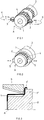
- FIG. 1 schematically shows the basic structure of a conventional impact rolling device for generating internal and external teeth on a cylindrical hollow body 1.
- the hollow body 1 is formed as a thin-walled pot, which on a profiled mandrel. 2 is postponed and processed from outside by means of arranged on a circular path K profile rollers 3 beating.
- the profile rollers 3 are thereby delivered radially against the axis A of the hollow body until the desired tread depth has been achieved on the hollow body 1.
- the profiles 4 are produced on the hollow body 1 at the front end with a straight end, while the profile ends tapering, with a radius corresponding to the shape of the circular path K ends. Now, if the profiles 4 must be formed close to a protruding radially outwardly of the hollow body 1 shoulder, so this process can be resp. do not use this device.
- FIG. 2 is now also schematically illustrated the basic structure of a device for machining cylindrical, thin-walled hollow bodies.
- a profiled mandrel 2 is used, on which the hollow body 1 to be profiled is placed.
- the hollow body 1 here now has an outwardly projecting shoulder 1 '.
- the profiles 4 should now be carried out from the front side to close to the shoulder.
- profiling tools 5 are now used, which can be delivered radially with respect to the axis A of the hollow body 1.
- the profiling tools 5 are driven by means of an eccentric drive (not shown for clarity) in a linear oscillating movement exactly radially to the axis A.
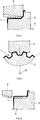
- FIG. 3 the longitudinal section through the mandrel 2 is shown with attached hollow body 1, wherein the profiling tool 5 is in the starting position for the processing of the shoulder 1 'of the hollow body 1.
- the hollow body 1 is pressed firmly against the mandrel 2 in the axial direction.
- the mandrel 2 has in particular a toothing resp. Longitudinal profiling on which the hollow body 1 rests with its inner side before machining.
- the mandrel 2 a shoulder 2 'on.
- the profiling tools 5 are now placed in the first process section in a sudden hammering action on the surface of the hollow body 1. Simultaneously with this oscillating movement of the profiling tools 5, these are now in the first process section radially against the axis A of the hollow body 1 to a previously defined resp. set depth, as shown in the longitudinal section FIG. 4 evident. At the end of this first process section, the profile is now formed in the region of the shoulder 1 ', while it is first preformed to the left to the front edge of the hollow body 1, but not yet fully formed.
- the profiling tools 5 may be operated at a speed of over 1000 beats per minute, for example even over 1500 beats per minute.
- the profiling tools 5 can be delivered in each case for each complete hollow body revolution in the radial direction in each case by at least about 0.1 mm until the desired tread depth is reached.
- FIG. 6 the longitudinal section through a hollow body 1 is analogous to FIG. 3 shown, in which case the profiling tool 5 is shown in its alternative starting position for processing.
- the profiling tool 5 is located axially in front of the end face of the hollow body 1, and is delivered radially in the predefined feed depth.
- the profiling tool 5 is now pushed axially in the direction of the shoulder 1 'of the hollow body 1 until reaching the desired profile length.
- the hollow body 1 is for example close to the end face of the mandrel 2, and the shoulder 1 'has against the shoulder 2' of the mandrel 2 on a small game.
- the material of the hollow body 1 during processing in the direction of this shoulder 2 'expand it is clear to the skilled person that this relative movement in the device itself by displacement of the hollow body 1, respectively. of the mandrel 2 relative to the profiling tool 5 can take place.
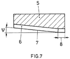
- FIG. 7 is still the longitudinal section of a profiling tool 5 shown, as it can be used for example for the claimed method.
- the profiling tool 5 is designed as a punch and has on its machining side 6 a cross-section to the profile 4 to be generated of the hollow body 1 corresponding shape, for example, a trapezoidal shape.
- the lower edge 7 of the machining side 6 is thereby arranged in relation to the axis A of the hollow body at an acute angle ⁇ . Depending on the shape and depth of the profile 4 to be produced, this angle is between 0.5 ° and 10 °.
- the lower edge 7 extends for example straight, but may also have a slight curvature.
- a calibration zone 8 is formed at the right end of the profiling tool 5 after FIG. 7 .
- the lower edge 7 is aligned parallel to the axis A of the hollow body 1, and the contour of the machining side 6 corresponds to the cross section of the profile to be produced on the outside of the hollow body 1.
- the lower edge 7 extends from the calibration zone 8 at an angle or possibly in an arc to the opposite end of the profiling tool 5. This angle resp. Arc corresponds to the contour of the preforming region of the profile 4 to be produced. It has been found that it can be advantageous if the length of the calibration zone 8 is only one Fraction of the total length of the profiling tool 5 corresponds.
- the axial feed of the hollow body 1 resp. of the mandrel 2 is to be tuned, for example, to the length of the calibration zone 8 and is when using two radially opposite profiling tools 5, for example, a maximum of twice this length in a full revolution of the hollow body.
- the stroke of the profiling tools 5 of the oscillating movement is dimensioned such that it is greater than the maximum radial infeed depth of the first method section.
- the profiling tools 5 arrive at each stroke once outside the contour of the surface of the hollow body 1.
- the hollow body respectively. the mandrel 2 in the same frequency as the oscillation of the profiling tool and synchronized to this movement, for example, intermittently rotated.
- the rotational movement is carried out, for example, exactly by a pitching step of the profiling, so that successive abrupt actions of the profiling tools 5 in adjacent profiles 4 of the hollow body 1 take place.
- a very precise and uniform profiling can be generated on the entire circumference of the hollow body 1.
- Very high production rates can be achieved by the already mentioned high rate of impact, which is particularly advantageous for mass production, for example in the automotive industry.
Landscapes
- Engineering & Computer Science (AREA)
- Mechanical Engineering (AREA)
- Forging (AREA)
- Turning (AREA)
- Shaping Metal By Deep-Drawing, Or The Like (AREA)
- Dental Prosthetics (AREA)
Claims (19)
- Procédé de profilation à froid de pièces creuses cylindriques (1) à paroi mince pour générer des dentures intérieures et extérieures sur les pièces creuses avec des profils qui s'étendent essentiellement en parallèle à l'axe longitudinal (A) de la pièce creuse (1), caractérisé en ce que
pour son traitement, la pièce creuse (1) est placée sur un mandrin profilé disposé à coulissement le long de l'axe longitudinal (A) par rapport à l'outil de profilation (5),
en ce qu'au moins un outil de profilation (5) relié fonctionnellement à un entraînement excentrique est amené à agir sur la pièce creuse (1) par percussions depuis l'extérieur, radialement par rapport à l'axe longitudinal (A) de la pièce creuse (1),
en ce que l'outil de profilation (5) est amené à agir sur la surface de la pièce creuse (1) en oscillant uniquement dans une direction essentiellement perpendiculaire,
en ce que la course oscillante de l'outil de profilation (5) est sélectionnée supérieure à la profondeur maximale de pénétration radiale de l'outil de profilation (5) dans la pièce creuse (1),
en ce que la pièce creuse (1) est tournée de manière intermittent autour de son axe longitudinal (A), de manière synchronisée avec la course oscillante, en particulier chaque fois de la distance du pas de la profilation à générer,
cependant l'outil de profilation (5) est déplacé axialement par rapport à la pièce creuse (1), la profondeur d'avance radiale étant constante, jusqu'à ce que soit atteinte la longueur souhaitée du profil,
cependant l'outil de profilation (5) est configuré comme poussoir présentant un côté de traitement (6) et présentant sur son côté de traitement (6) une forme dont la section transversale correspond au profil (4) à générer sur le corps creux (1),
cependant le côté de traitement (6) présente une arête inférieure (7) disposée en coupe longitudinale à un angle aigu par rapport à l'axe longitudinal (A), une zone d'étalonnage (8) étant formée sur une extrémité de l'outil de profilation (5) et l'arête inférieure (7) étant orientée en coupe longitudinale parallèlement à l'axe longitudinal (A) dans la zone d'étalonnage (8) et, en coupe transversale, le contour de la zone de traitement (6) correspond au profil à générer sur le côté extérieur du corps creux (1), et cependant l'arête inférieure (7) présentant dans la zone d'étalonnage (8) la plus courte distance radiale par rapport à la surface du corps creux (1). - Procédé selon la revendication 1, caractérisé en ce qu'avant le déplacement axial, l'outil de profilation (5) est avancé radialement jusqu'à une profondeur d'avancement prédéfinie en direction de l'axe longitudinal de la pièce creuse (1).
- Procédé selon les revendications 1 ou 2, caractérisé en ce qu'au moins une fois, un changement de direction du déplacement axial est réalisé entre l'outil de profilation (5) et la pièce creuse (1), par exemple après que la longueur souhaitée du profil a été atteinte, retour à la position de départ initiale.
- Procédé selon l'une des revendications 1 à 3, caractérisé en ce qu'après chaque fin du déplacement axial relatif, l'outil de profilation (5) est extrait radialement hors du profil (4) de la pièce creuse (1).
- Procédé selon l'une des revendications 1 à 4, caractérisé en ce que la profilation du mandrin (2) s'étend depuis son extrémité libre jusqu'à un épaulement (2') qui déborde radialement vers l'extérieur et en ce que la pièce creuse (1) placée est configurée en forme de godet et présente une bordure ou un épaulement (1').
- Procédé selon la revendication 5, caractérisé en ce que l'outil de profilation (5) est d'abord amené à agir radialement au niveau de l'épaulement (2') du mandrin (2) ou au niveau du bord (1') de la pièce creuse (1), le mandrin (2) ou la pièce creuse (1) étant ensuite éloignés axialement de l'épaulement (2') ou du bord (1') par rapport à l'outil de profilation (5), par exemple jusqu'à ce que l'outil de profilation (5) n'agisse plus sur la pièce creuse (1).
- Procédé selon la revendication 5, caractérisé en ce que l'outil de profilation (5) est avancé radialement jusqu'à une profondeur d'avancement définie au niveau de l'extrémité libre de la pièce creuse (1) ou du mandrin (2), le mandrin (2) étant ensuite déplacé axialement par rapport à l'outil de profilation (5), par exemple jusqu'à ce que l'outil de profilation (5) agisse étroitement sur l'épaulement (2') du mandrin (2) ou sur le bord (1') de la pièce creux (1).
- Procédé selon l'une des revendications 1 à 7, caractérisé en ce qu'au moins deux outils de profilation (5) disposés l'un en face de l'autre dans la direction radiale sont utilisés, par example entraînés de manière synchronisée l'un par rapport à l'autre, tant pour leur avance radiale que pour leur déplacement d'oscillation.
- Procédé selon l'une des revendications 1 à 8, caractérisé en ce que l'outil de profilation (5) est avancé de manière continue ou par étapes distinctes et réglable par rapport au corps creux (1), jusqu'à ce que la profondeur finale du profil (4) de la pièce creuse (1) soit atteinte.
- Dispositif pour de l'exécution du procédé selon l'une des revendications 1 à 9, présentant :un entraînement excentrique,au moins un outil de profilation (5) relié fonctionnellement à l'entraînement excentrique qui forme la course oscillante de l'outil de profilation (5),un porte-pièce présentant la forme d'un mandrin profilé (2) pour la pièce creuse (1), configuré pour pouvoir coulisser par rapport à l'outil de profilation (5) le long de son axe longitudinal (A),un entraînement permettant de faire tourner autour de son axe longitudinal (A) le mandrin (2) de manière intermittente et synchronisée par rapport à la course oscillante,cependent l'outil de profilation (5) étant configuré comme poussoir ayant un côté de traitement (6) et présentant sur son côté de traitement (6) une forme qui correspond en coupe transversale au profil (4) qui doit être formé sur le corps creux (1),le côté de traitement (6) présentant une arête inférieure (7) qui, en coupe longitudinale, est disposée sous un angle aigu par rapport à l'axe longitudinal (A), cependent une zone d'étalonnage (8) étant formée sur une extrémité de l'outil de profilation (5) et l'arête inférieure (7) étant orientée en coupe longitudinale parallèlement à l'axe longitudinal (A) dans la zone d'étalonnage (8) et, en coupe transversale, le contour de la zone de traitement (6) correspondant au profil à générer sur le côté extérieur du corps creux (1), et cependent l'arête inférieure (7) présentant dans la zone d'étalonnage (8) la plus courte distance radiale par rapport à la surface du corps creux (1).
- Ensemble selon la revendication 10, caractérisé en ce que la longueur du poussoir (5) ou la longueur du profil de travail est supérieure à la longueur du profil (4) qui doit être généré dans le corps creux (1).
- Ensemble selon les revendications 10 ou 11, caractérisé en ce que la longueur de la zone d'étalonnage (8) ne forme qu'une fraction de la longueur totale du poussoir (5) ou de la longueur du profil de travail.
- Ensemble selon les revendications 10 à 12, caractérisé en ce qu'il présente au moins deux outils de profilation (5) disposés l'un en face de l'autre par rapport à l'axe longitudinal (A) du corps creux (1).
- Ensemble selon la revendication 10, caractérisé en ce que la profilation du mandrin (2) s'étend depuis son extrémité libre jusqu'à un épaulement (2) débordant radialement vers l'extérieur.
- Ensemble selon la revendication 14, caractérisé en ce que le mandrin (2) convient pour y placer une pièce creuse (1) configurée en forme de godet et présentant un bord ou un épaulement (1').
- Ensemble selon la revendication 10, caractérisé en ce que selon la forme et la profondeur du profil (4) à générer, l'angle aigu est compris entre 0,5° et 10°.
- Ensemble selon la revendication 10, caractérisé en ce que l'arête inférieure (7) s'étend depuis la zone d'étalonnage (8) en formant un angle ou un arc jusqu'à l'extrémité opposée de l'outil de profilation (5).
- Ensemble selon la revendication 17, caractérisé en ce que cet angle ou cet arc correspondent au contour d'une partie d'ébauchage du profil (4) à générer.
- Utilisation d'un procédé selon la revendication 5 ou le dispositif selon la revendication 14 pour la profilation à froid de pièces creuses cylindriques (1) à paroi mince, poue générer des dentures intérieures et des dentures extérieures sur les pièces creuses, avec des profils qui s'étendent essentiellement en parallèle à l'axe longitudinal (A) de la pièce creuse (1), cependent les pièces creuses (1) étant configurées en forme de godet et présentant un épaulement ou un bord, ces pièces creuses étant des pièces creuses utilisées en construction de transmissions servant à transférer des rotations et des moments de rotation dans des transmissions automatiques.
Applications Claiming Priority (1)
| Application Number | Priority Date | Filing Date | Title |
|---|---|---|---|
| PCT/CH2005/000406 WO2007009267A1 (fr) | 2005-07-15 | 2005-07-15 | Procede pour realiser des dentures interieures et exterieures sur des pieces creuses cylindriques a paroi mince |
Publications (2)
| Publication Number | Publication Date |
|---|---|
| EP1915225A1 EP1915225A1 (fr) | 2008-04-30 |
| EP1915225B1 true EP1915225B1 (fr) | 2017-11-01 |
Family
ID=35735096
Family Applications (1)
| Application Number | Title | Priority Date | Filing Date |
|---|---|---|---|
| EP05758521.8A Expired - Lifetime EP1915225B1 (fr) | 2005-07-15 | 2005-07-15 | Procede pour realiser des dentures interieures et exterieures sur des pieces creuses cylindriques a paroi mince |
Country Status (8)
| Country | Link |
|---|---|
| US (1) | US8117884B2 (fr) |
| EP (1) | EP1915225B1 (fr) |
| JP (1) | JP4873661B2 (fr) |
| KR (1) | KR101292287B1 (fr) |
| CN (1) | CN101198425B (fr) |
| CA (1) | CA2615220C (fr) |
| ES (1) | ES2676420T3 (fr) |
| WO (1) | WO2007009267A1 (fr) |
Families Citing this family (18)
| Publication number | Priority date | Publication date | Assignee | Title |
|---|---|---|---|---|
| CH706436A1 (de) * | 2012-04-25 | 2013-10-31 | Grob Ernst Fa | Verfahren und Vorrichtung zur Herstellung von mit einer innenliegenden Laufradverzahnung versehenen dickwandigen Hohlrädern. |
| CN102990472B (zh) * | 2012-11-17 | 2016-06-22 | 山东省青岛生建机械厂 | 高速间歇分度机构 |
| AT514020B1 (de) * | 2013-03-07 | 2015-05-15 | Steyr Mannlicher Gmbh | Verfahren zum Herstellen eines Laufs mit Laufflutungen |
| KR102282551B1 (ko) | 2013-09-04 | 2021-07-27 | 이데미쓰 고산 가부시키가이샤 | 카바졸 유도체, 이것을 이용한 유기 전기발광 소자용 재료, 및 이것을 이용한 유기 전기발광 소자 및 전자 기기 |
| EP3060825B1 (fr) * | 2013-10-23 | 2021-02-24 | Ernst Grob AG | Disque de frein composite ainsi que procédé et dispositif pour le fabriquer |
| EP2982456B1 (fr) * | 2014-08-05 | 2016-11-30 | Feintool International Holding AG | Dispositif et procédé de fabrication d'un élément de couplage à dents ou ayant des parties dentées adaptées aux systèmes de synchronisation |
| CN105436327B (zh) * | 2014-08-12 | 2018-02-02 | 博世华域转向系统(烟台)有限公司 | 一种转向管柱的下转向轴花键用铆压装置 |
| US9890808B2 (en) | 2015-04-22 | 2018-02-13 | American Axle & Manufacturing, Inc. | Telescoping propshaft |
| DE102016103946A1 (de) * | 2016-03-04 | 2017-09-07 | Leifeld Metal Spinning Ag | Verfahren und Vorrichtung zum Umformen eines Werkstücks mit trommelförmiger Umfangswand |
| US10837072B2 (en) * | 2016-08-29 | 2020-11-17 | Magna Powertrain Inc. | Splined power transmission components made using heat-assisted calibration process and method of forming such splined power transmission components |
| CN108246917B (zh) * | 2018-02-05 | 2020-02-07 | 吉林大学 | 一种离合器毂齿形辊压成形装置及加工工艺 |
| CH714660A1 (de) * | 2018-02-16 | 2019-08-30 | Grob Ernst Fa | Vorrichtung und Verfahren zur Herstellung eines Hohlrades mit Innen- und Aussenverzahnung sowie Hohlrad. |
| CH714772A1 (de) * | 2018-11-15 | 2019-09-13 | Grob Ernst Fa | Vorrichtung und Verfahren zum kaltumformenden Profilieren von Werkstücken. |
| EP3670018A1 (fr) * | 2018-12-20 | 2020-06-24 | Leifeld Metal Spinning AG | Procédé et installation de formage permettant de fabriquer une partie d'engrenage en forme de tambour |
| EP3711707B1 (fr) * | 2019-03-21 | 2022-01-19 | SIRONA Dental Systems GmbH | Orientation relative entre des outils de traitement couplés et des corps d'ébauche |
| CN111014392B (zh) * | 2019-12-06 | 2021-08-27 | 吉林大学 | 一种离合器毂齿形轴向多点辊压成形装置 |
| CN111842754B (zh) * | 2020-07-08 | 2021-08-27 | 西安交通大学 | 圆弧齿底非渐开线齿形四锤头渐进径向锻造装置及工艺 |
| CH718706A1 (de) | 2021-06-04 | 2022-12-15 | Grob Ernst Fa | Vorrichtung und Verfahren zum kaltumformenden Profilieren von Werkstücken. |
Family Cites Families (9)
| Publication number | Priority date | Publication date | Assignee | Title |
|---|---|---|---|---|
| US1324090A (en) * | 1915-10-19 | 1919-12-09 | Lorillard Co P | Bale-band tightener. |
| DE1280198B (de) * | 1961-07-07 | 1968-10-17 | Grob Ernst Fa | Verfahren zum spanlosen Profilieren, vorzugsweise Verzahnen, von zylindrischen metallischen Werkstuecken und Vorrichtung zur Durchfuehrung des Verfahrens |
| US3352138A (en) * | 1965-10-23 | 1967-11-14 | Barber Colman Co | Tool for forming toothed parts |
| DE2401671A1 (de) * | 1974-01-15 | 1975-07-24 | Rueggeberg August Fa | Verfahren zur herstellung einer feile aus einem duennwandigen rohr |
| JP3089369B2 (ja) * | 1992-02-04 | 2000-09-18 | 本田技研工業株式会社 | スナップリング溝を有するスプライン付きカップ状製品の成形装置 |
| JPH0679390A (ja) * | 1992-09-04 | 1994-03-22 | Mitsubishi Heavy Ind Ltd | 棒状物の鍛造方法 |
| JPH07265990A (ja) * | 1994-03-28 | 1995-10-17 | Mazda Motor Corp | 円筒部品成形方法および成形装置 |
| JP3281175B2 (ja) * | 1994-04-18 | 2002-05-13 | 株式会社東芝 | プレス成形装置 |
| FR2755042B1 (fr) * | 1996-10-24 | 1998-12-24 | Lemforder Nacam Sa | Procede d'obtention de cannelures sur un arbre |
-
2005
- 2005-07-15 CA CA2615220A patent/CA2615220C/fr not_active Expired - Fee Related
- 2005-07-15 WO PCT/CH2005/000406 patent/WO2007009267A1/fr not_active Ceased
- 2005-07-15 JP JP2008520686A patent/JP4873661B2/ja not_active Expired - Fee Related
- 2005-07-15 EP EP05758521.8A patent/EP1915225B1/fr not_active Expired - Lifetime
- 2005-07-15 KR KR1020087002571A patent/KR101292287B1/ko not_active Expired - Fee Related
- 2005-07-15 US US11/994,376 patent/US8117884B2/en active Active
- 2005-07-15 ES ES05758521.8T patent/ES2676420T3/es not_active Expired - Lifetime
- 2005-07-15 CN CN200580050082XA patent/CN101198425B/zh not_active Expired - Fee Related
Non-Patent Citations (1)
| Title |
|---|
| None * |
Also Published As
| Publication number | Publication date |
|---|---|
| KR101292287B1 (ko) | 2013-08-01 |
| US8117884B2 (en) | 2012-02-21 |
| US20100126020A1 (en) | 2010-05-27 |
| CN101198425A (zh) | 2008-06-11 |
| CN101198425B (zh) | 2011-06-08 |
| ES2676420T3 (es) | 2018-07-19 |
| JP4873661B2 (ja) | 2012-02-08 |
| JP2009500179A (ja) | 2009-01-08 |
| CA2615220C (fr) | 2013-01-08 |
| CA2615220A1 (fr) | 2007-01-25 |
| KR20080030071A (ko) | 2008-04-03 |
| EP1915225A1 (fr) | 2008-04-30 |
| WO2007009267A1 (fr) | 2007-01-25 |
Similar Documents
| Publication | Publication Date | Title |
|---|---|---|
| EP1915225B1 (fr) | Procede pour realiser des dentures interieures et exterieures sur des pieces creuses cylindriques a paroi mince | |
| DE102012017525B4 (de) | Verfahren zur umformenden Herstellung eines Zahnrads mit Außenverzahnung, sowie nach diesem Verfahren herstellbares Zahnrad mit Außenverzahnung | |
| EP0921879B1 (fr) | Procede et dispositif de fabrication d'une partie d'engrenage a denture exterieure | |
| EP1629919A2 (fr) | Outil et et son utilisation pour la réalisation de taraudages | |
| DE102006026992B4 (de) | Verfahren zur Erzeugung eines Gewindes in wenigstens zwei Arbeitsschritten | |
| EP0955110B1 (fr) | Procédé et dispositif pour le fluotournage | |
| DE102013112123B4 (de) | Metallhülse und Verfahren zu deren Herstellung | |
| EP2794167B1 (fr) | Outil combiné et procédé de réalisation d'une structure superficielle avec des contre-dépouilles dans la surface d'une pièce | |
| EP0313985A2 (fr) | Procédé de fabrication d'un arbre à cames | |
| DE19723073C2 (de) | Verfahren zur Herstellung eines rotationssymmetrischen Werkstücks | |
| DE3879712T2 (de) | Verfahren zur bearbeitung eines laenglichen werkstueckes und vorrichtung dazu. | |
| DE102011102288B4 (de) | Vorrichtung und Verfahren zur Herstellung eines Stirnrads mit einer Schrägverzahnung | |
| EP2841218B1 (fr) | Dispositif et procédé de fabrication de couronnes à parois épaisses pourvues d'une denture intérieure de roue de roulement | |
| EP3670018A1 (fr) | Procédé et installation de formage permettant de fabriquer une partie d'engrenage en forme de tambour | |
| EP3246104B1 (fr) | Procede et dispositif de fabrication d'une piece de formage | |
| EP0808678A1 (fr) | Méthode et dispositif pour le fabrication d'une poulie à gorges multiples | |
| DE102017116895A1 (de) | Verfahren und Vorrichtung zur Herstellung einer Verzahnung an einem zylindrischen Werkstück | |
| DE19629738C2 (de) | Verfahren zum Herstellen rotationssymmetrischer Körper mit Nabe | |
| DE19954210B4 (de) | Rundknetmaschine | |
| DE4321779B4 (de) | Verfahren zur Herstellung eines Starterkranz-Zahnrads aus Blech und nach dem Verfahren hergestelltes Starterkranz-Zahnrad | |
| DE102009058178B4 (de) | Verfahren und Werkzeug zur Oberflächenbehandlung | |
| EP1713600A1 (fr) | Dispositif et procede de production de profils de type dente sur des pieces | |
| DE102011011886B4 (de) | Verfahren zum Verdichten der Oberfläche von Sintermetallbauteilen | |
| DE102017212054A1 (de) | Verfahren zur Herstellung eines Schneidkopfes sowie Schneidkopf | |
| EP1646461A1 (fr) | Procede et dispositif d'usinage de zones marginales de corps creux cylindres |
Legal Events
| Date | Code | Title | Description |
|---|---|---|---|
| PUAI | Public reference made under article 153(3) epc to a published international application that has entered the european phase |
Free format text: ORIGINAL CODE: 0009012 |
|
| 17P | Request for examination filed |
Effective date: 20070601 |
|
| AK | Designated contracting states |
Kind code of ref document: A1 Designated state(s): AT BE BG CH CY CZ DE DK EE ES FI FR GB GR HU IE IS IT LI LT LU LV MC NL PL PT RO SE SI SK TR |
|
| 17Q | First examination report despatched |
Effective date: 20080520 |
|
| DAX | Request for extension of the european patent (deleted) | ||
| GRAP | Despatch of communication of intention to grant a patent |
Free format text: ORIGINAL CODE: EPIDOSNIGR1 |
|
| STAA | Information on the status of an ep patent application or granted ep patent |
Free format text: STATUS: GRANT OF PATENT IS INTENDED |
|
| INTG | Intention to grant announced |
Effective date: 20161125 |
|
| GRAJ | Information related to disapproval of communication of intention to grant by the applicant or resumption of examination proceedings by the epo deleted |
Free format text: ORIGINAL CODE: EPIDOSDIGR1 |
|
| STAA | Information on the status of an ep patent application or granted ep patent |
Free format text: STATUS: EXAMINATION IS IN PROGRESS |
|
| INTC | Intention to grant announced (deleted) | ||
| GRAP | Despatch of communication of intention to grant a patent |
Free format text: ORIGINAL CODE: EPIDOSNIGR1 |
|
| STAA | Information on the status of an ep patent application or granted ep patent |
Free format text: STATUS: GRANT OF PATENT IS INTENDED |
|
| INTG | Intention to grant announced |
Effective date: 20170606 |
|
| GRAS | Grant fee paid |
Free format text: ORIGINAL CODE: EPIDOSNIGR3 |
|
| GRAA | (expected) grant |
Free format text: ORIGINAL CODE: 0009210 |
|
| STAA | Information on the status of an ep patent application or granted ep patent |
Free format text: STATUS: THE PATENT HAS BEEN GRANTED |
|
| AK | Designated contracting states |
Kind code of ref document: B1 Designated state(s): AT BE BG CH CY CZ DE DK EE ES FI FR GB GR HU IE IS IT LI LT LU LV MC NL PL PT RO SE SI SK TR |
|
| REG | Reference to a national code |
Ref country code: GB Ref legal event code: FG4D Free format text: NOT ENGLISH |
|
| REG | Reference to a national code |
Ref country code: CH Ref legal event code: EP Ref country code: AT Ref legal event code: REF Ref document number: 941554 Country of ref document: AT Kind code of ref document: T Effective date: 20171115 |
|
| REG | Reference to a national code |
Ref country code: IE Ref legal event code: FG4D Free format text: LANGUAGE OF EP DOCUMENT: GERMAN |
|
| REG | Reference to a national code |
Ref country code: DE Ref legal event code: R096 Ref document number: 502005015736 Country of ref document: DE |
|
| REG | Reference to a national code |
Ref country code: CH Ref legal event code: NV Representative=s name: FREI PATENTANWALTSBUERO AG, CH |
|
| REG | Reference to a national code |
Ref country code: NL Ref legal event code: MP Effective date: 20171101 |
|
| REG | Reference to a national code |
Ref country code: LT Ref legal event code: MG4D |
|
| PG25 | Lapsed in a contracting state [announced via postgrant information from national office to epo] |
Ref country code: LT Free format text: LAPSE BECAUSE OF FAILURE TO SUBMIT A TRANSLATION OF THE DESCRIPTION OR TO PAY THE FEE WITHIN THE PRESCRIBED TIME-LIMIT Effective date: 20171101 Ref country code: SE Free format text: LAPSE BECAUSE OF FAILURE TO SUBMIT A TRANSLATION OF THE DESCRIPTION OR TO PAY THE FEE WITHIN THE PRESCRIBED TIME-LIMIT Effective date: 20171101 Ref country code: NL Free format text: LAPSE BECAUSE OF FAILURE TO SUBMIT A TRANSLATION OF THE DESCRIPTION OR TO PAY THE FEE WITHIN THE PRESCRIBED TIME-LIMIT Effective date: 20171101 Ref country code: FI Free format text: LAPSE BECAUSE OF FAILURE TO SUBMIT A TRANSLATION OF THE DESCRIPTION OR TO PAY THE FEE WITHIN THE PRESCRIBED TIME-LIMIT Effective date: 20171101 |
|
| PG25 | Lapsed in a contracting state [announced via postgrant information from national office to epo] |
Ref country code: LV Free format text: LAPSE BECAUSE OF FAILURE TO SUBMIT A TRANSLATION OF THE DESCRIPTION OR TO PAY THE FEE WITHIN THE PRESCRIBED TIME-LIMIT Effective date: 20171101 Ref country code: GR Free format text: LAPSE BECAUSE OF FAILURE TO SUBMIT A TRANSLATION OF THE DESCRIPTION OR TO PAY THE FEE WITHIN THE PRESCRIBED TIME-LIMIT Effective date: 20180202 Ref country code: IS Free format text: LAPSE BECAUSE OF FAILURE TO SUBMIT A TRANSLATION OF THE DESCRIPTION OR TO PAY THE FEE WITHIN THE PRESCRIBED TIME-LIMIT Effective date: 20180301 Ref country code: BG Free format text: LAPSE BECAUSE OF FAILURE TO SUBMIT A TRANSLATION OF THE DESCRIPTION OR TO PAY THE FEE WITHIN THE PRESCRIBED TIME-LIMIT Effective date: 20180201 |
|
| REG | Reference to a national code |
Ref country code: ES Ref legal event code: FG2A Ref document number: 2676420 Country of ref document: ES Kind code of ref document: T3 Effective date: 20180719 |
|
| REG | Reference to a national code |
Ref country code: FR Ref legal event code: PLFP Year of fee payment: 14 |
|
| PG25 | Lapsed in a contracting state [announced via postgrant information from national office to epo] |
Ref country code: DK Free format text: LAPSE BECAUSE OF FAILURE TO SUBMIT A TRANSLATION OF THE DESCRIPTION OR TO PAY THE FEE WITHIN THE PRESCRIBED TIME-LIMIT Effective date: 20171101 Ref country code: CZ Free format text: LAPSE BECAUSE OF FAILURE TO SUBMIT A TRANSLATION OF THE DESCRIPTION OR TO PAY THE FEE WITHIN THE PRESCRIBED TIME-LIMIT Effective date: 20171101 Ref country code: CY Free format text: LAPSE BECAUSE OF FAILURE TO SUBMIT A TRANSLATION OF THE DESCRIPTION OR TO PAY THE FEE WITHIN THE PRESCRIBED TIME-LIMIT Effective date: 20171101 Ref country code: EE Free format text: LAPSE BECAUSE OF FAILURE TO SUBMIT A TRANSLATION OF THE DESCRIPTION OR TO PAY THE FEE WITHIN THE PRESCRIBED TIME-LIMIT Effective date: 20171101 Ref country code: SK Free format text: LAPSE BECAUSE OF FAILURE TO SUBMIT A TRANSLATION OF THE DESCRIPTION OR TO PAY THE FEE WITHIN THE PRESCRIBED TIME-LIMIT Effective date: 20171101 |
|
| REG | Reference to a national code |
Ref country code: DE Ref legal event code: R097 Ref document number: 502005015736 Country of ref document: DE |
|
| PG25 | Lapsed in a contracting state [announced via postgrant information from national office to epo] |
Ref country code: RO Free format text: LAPSE BECAUSE OF FAILURE TO SUBMIT A TRANSLATION OF THE DESCRIPTION OR TO PAY THE FEE WITHIN THE PRESCRIBED TIME-LIMIT Effective date: 20171101 Ref country code: PL Free format text: LAPSE BECAUSE OF FAILURE TO SUBMIT A TRANSLATION OF THE DESCRIPTION OR TO PAY THE FEE WITHIN THE PRESCRIBED TIME-LIMIT Effective date: 20171101 |
|
| PLBE | No opposition filed within time limit |
Free format text: ORIGINAL CODE: 0009261 |
|
| STAA | Information on the status of an ep patent application or granted ep patent |
Free format text: STATUS: NO OPPOSITION FILED WITHIN TIME LIMIT |
|
| 26N | No opposition filed |
Effective date: 20180802 |
|
| PGFP | Annual fee paid to national office [announced via postgrant information from national office to epo] |
Ref country code: ES Payment date: 20180829 Year of fee payment: 14 Ref country code: IT Payment date: 20180724 Year of fee payment: 14 Ref country code: FR Payment date: 20180725 Year of fee payment: 14 |
|
| REG | Reference to a national code |
Ref country code: CH Ref legal event code: PCAR Free format text: NEW ADDRESS: POSTFACH, 8032 ZUERICH (CH) |
|
| PG25 | Lapsed in a contracting state [announced via postgrant information from national office to epo] |
Ref country code: SI Free format text: LAPSE BECAUSE OF FAILURE TO SUBMIT A TRANSLATION OF THE DESCRIPTION OR TO PAY THE FEE WITHIN THE PRESCRIBED TIME-LIMIT Effective date: 20171101 |
|
| PGFP | Annual fee paid to national office [announced via postgrant information from national office to epo] |
Ref country code: GB Payment date: 20180719 Year of fee payment: 14 Ref country code: TR Payment date: 20180712 Year of fee payment: 14 |
|
| PG25 | Lapsed in a contracting state [announced via postgrant information from national office to epo] |
Ref country code: LU Free format text: LAPSE BECAUSE OF NON-PAYMENT OF DUE FEES Effective date: 20180715 Ref country code: MC Free format text: LAPSE BECAUSE OF FAILURE TO SUBMIT A TRANSLATION OF THE DESCRIPTION OR TO PAY THE FEE WITHIN THE PRESCRIBED TIME-LIMIT Effective date: 20171101 |
|
| REG | Reference to a national code |
Ref country code: BE Ref legal event code: MM Effective date: 20180731 |
|
| REG | Reference to a national code |
Ref country code: IE Ref legal event code: MM4A |
|
| PG25 | Lapsed in a contracting state [announced via postgrant information from national office to epo] |
Ref country code: IE Free format text: LAPSE BECAUSE OF NON-PAYMENT OF DUE FEES Effective date: 20180715 |
|
| PG25 | Lapsed in a contracting state [announced via postgrant information from national office to epo] |
Ref country code: BE Free format text: LAPSE BECAUSE OF NON-PAYMENT OF DUE FEES Effective date: 20180731 |
|
| REG | Reference to a national code |
Ref country code: AT Ref legal event code: MM01 Ref document number: 941554 Country of ref document: AT Kind code of ref document: T Effective date: 20180715 |
|
| PG25 | Lapsed in a contracting state [announced via postgrant information from national office to epo] |
Ref country code: AT Free format text: LAPSE BECAUSE OF NON-PAYMENT OF DUE FEES Effective date: 20180715 |
|
| GBPC | Gb: european patent ceased through non-payment of renewal fee |
Effective date: 20190715 |
|
| PG25 | Lapsed in a contracting state [announced via postgrant information from national office to epo] |
Ref country code: GB Free format text: LAPSE BECAUSE OF NON-PAYMENT OF DUE FEES Effective date: 20190715 |
|
| PG25 | Lapsed in a contracting state [announced via postgrant information from national office to epo] |
Ref country code: PT Free format text: LAPSE BECAUSE OF FAILURE TO SUBMIT A TRANSLATION OF THE DESCRIPTION OR TO PAY THE FEE WITHIN THE PRESCRIBED TIME-LIMIT Effective date: 20171101 Ref country code: HU Free format text: LAPSE BECAUSE OF FAILURE TO SUBMIT A TRANSLATION OF THE DESCRIPTION OR TO PAY THE FEE WITHIN THE PRESCRIBED TIME-LIMIT; INVALID AB INITIO Effective date: 20050715 |
|
| PG25 | Lapsed in a contracting state [announced via postgrant information from national office to epo] |
Ref country code: FR Free format text: LAPSE BECAUSE OF NON-PAYMENT OF DUE FEES Effective date: 20190731 |
|
| PG25 | Lapsed in a contracting state [announced via postgrant information from national office to epo] |
Ref country code: IT Free format text: LAPSE BECAUSE OF NON-PAYMENT OF DUE FEES Effective date: 20190715 |
|
| REG | Reference to a national code |
Ref country code: ES Ref legal event code: FD2A Effective date: 20201130 |
|
| PG25 | Lapsed in a contracting state [announced via postgrant information from national office to epo] |
Ref country code: ES Free format text: LAPSE BECAUSE OF NON-PAYMENT OF DUE FEES Effective date: 20190716 |
|
| PGFP | Annual fee paid to national office [announced via postgrant information from national office to epo] |
Ref country code: DE Payment date: 20210721 Year of fee payment: 17 |
|
| PG25 | Lapsed in a contracting state [announced via postgrant information from national office to epo] |
Ref country code: TR Free format text: LAPSE BECAUSE OF NON-PAYMENT OF DUE FEES Effective date: 20190715 |
|
| REG | Reference to a national code |
Ref country code: DE Ref legal event code: R119 Ref document number: 502005015736 Country of ref document: DE |
|
| PG25 | Lapsed in a contracting state [announced via postgrant information from national office to epo] |
Ref country code: DE Free format text: LAPSE BECAUSE OF NON-PAYMENT OF DUE FEES Effective date: 20230201 |
|
| PGFP | Annual fee paid to national office [announced via postgrant information from national office to epo] |
Ref country code: CH Payment date: 20230801 Year of fee payment: 19 |
|
| REG | Reference to a national code |
Ref country code: CH Ref legal event code: PL |
|
| PG25 | Lapsed in a contracting state [announced via postgrant information from national office to epo] |
Ref country code: CH Free format text: LAPSE BECAUSE OF NON-PAYMENT OF DUE FEES Effective date: 20240731 |