EP1915535B1 - Dispositif ameliore pour l'adaptation du debit d'un compresseur mobile de type a vis a injection d'huile - Google Patents
Dispositif ameliore pour l'adaptation du debit d'un compresseur mobile de type a vis a injection d'huile Download PDFInfo
- Publication number
- EP1915535B1 EP1915535B1 EP06790451.6A EP06790451A EP1915535B1 EP 1915535 B1 EP1915535 B1 EP 1915535B1 EP 06790451 A EP06790451 A EP 06790451A EP 1915535 B1 EP1915535 B1 EP 1915535B1
- Authority
- EP
- European Patent Office
- Prior art keywords
- pressure
- valve
- control
- inlet
- type compressor
- Prior art date
- Legal status (The legal status is an assumption and is not a legal conclusion. Google has not performed a legal analysis and makes no representation as to the accuracy of the status listed.)
- Active
Links
Images


Classifications
-
- F—MECHANICAL ENGINEERING; LIGHTING; HEATING; WEAPONS; BLASTING
- F04—POSITIVE - DISPLACEMENT MACHINES FOR LIQUIDS; PUMPS FOR LIQUIDS OR ELASTIC FLUIDS
- F04C—ROTARY-PISTON, OR OSCILLATING-PISTON, POSITIVE-DISPLACEMENT MACHINES FOR LIQUIDS; ROTARY-PISTON, OR OSCILLATING-PISTON, POSITIVE-DISPLACEMENT PUMPS
- F04C28/00—Control of, monitoring of, or safety arrangements for, pumps or pumping installations specially adapted for elastic fluids
- F04C28/08—Control of, monitoring of, or safety arrangements for, pumps or pumping installations specially adapted for elastic fluids characterised by varying the rotational speed
-
- F—MECHANICAL ENGINEERING; LIGHTING; HEATING; WEAPONS; BLASTING
- F04—POSITIVE - DISPLACEMENT MACHINES FOR LIQUIDS; PUMPS FOR LIQUIDS OR ELASTIC FLUIDS
- F04C—ROTARY-PISTON, OR OSCILLATING-PISTON, POSITIVE-DISPLACEMENT MACHINES FOR LIQUIDS; ROTARY-PISTON, OR OSCILLATING-PISTON, POSITIVE-DISPLACEMENT PUMPS
- F04C28/00—Control of, monitoring of, or safety arrangements for, pumps or pumping installations specially adapted for elastic fluids
- F04C28/24—Control of, monitoring of, or safety arrangements for, pumps or pumping installations specially adapted for elastic fluids characterised by using valves controlling pressure or flow rate, e.g. discharge valves or unloading valves
-
- Y—GENERAL TAGGING OF NEW TECHNOLOGICAL DEVELOPMENTS; GENERAL TAGGING OF CROSS-SECTIONAL TECHNOLOGIES SPANNING OVER SEVERAL SECTIONS OF THE IPC; TECHNICAL SUBJECTS COVERED BY FORMER USPC CROSS-REFERENCE ART COLLECTIONS [XRACs] AND DIGESTS
- Y10—TECHNICAL SUBJECTS COVERED BY FORMER USPC
- Y10T—TECHNICAL SUBJECTS COVERED BY FORMER US CLASSIFICATION
- Y10T137/00—Fluid handling
- Y10T137/2496—Self-proportioning or correlating systems
- Y10T137/2559—Self-controlled branched flow systems
- Y10T137/2574—Bypass or relief controlled by main line fluid condition
Definitions
- the present invention concerns an improved device for adjusting the flow rate of a mobile oil-injected screw-type compressor.
- the present invention concerns an improved device for adjusting the flow rate of mobile oil-injected screw-type compressors which are driven by a thermal motor and which can typically provide operating pressures from 5 to 35 bar, whereby also the supplied flow rate of compressed gas can be adjusted in a sliding manner between 0 and 100 %.
- Such devices for adjusting the flow rate of a mobile oil-injected screw-type compressor which are driven by a thermal motor are already known, whereby the screw-type compressor is provided with an inlet and with an outlet onto which is connected a pressure vessel with an outlet pipe for supplying a compressed gas and whereby the device mainly consists of a control valve which is connected with its input to the pressure vessel via a pressure pipe and which, at its output, as of a certain pre-determined value of the pressure in the pressure pipe of the pressure vessel, supplies a control pressure which is in proportion to said pressure in the pressure pipe of the pressure vessel; an electronic speed controller for adjusting the rotational speed of the motor which is connected to the above-mentioned control pressure of the control valve via a pressure sensor and a first control, line and which is such that, as the control pressure rises, the motor is set at a lower rotational speed; and of a pneumatically controlled inlet valve on the inlet of the compressor, which inlet valve consists of a housing in which a valve element can be shifted to and
- valve element of the inlet valve of the compressor is moreover pushed in an open position by means of a compression spring during start up.
- a disadvantage of these known devices for adjusting the flow rate of a mobile oil-injected screw-type compressor is that, during a cold start up, there is not enough torque.
- the present invention aims to remedy one or several of the above-mentioned and other disadvantages in a simple manner.
- the invention concerns an improved device for adjusting the flow rate of a mobile oil-injected screw-type compressor of the above-mentioned type, whereby the valve element can move freely in the housing and whereby, in the line connecting the pressure chamber of the inlet valve to the control pressure of the control valve is provided a non-return valve actuated by means of a spring which can be pushed open by the control pressure.
- An advantage of such an improved device is that it provides a very simple solution to the high torque problem when starting the screw-type compressor, and moreover it consumes considerably less.
- a bypass line is provided between the pressure pipe on the pressure vessel and the above-mentioned second control line of the inlet valve, more particularly the part of the control line between the inlet valve and the non-return valve, whereby in this bypass line is provided a normally closed load valve which is opened as the compressor is started up.
- An advantage of an improved device is that, by opening the above-mentioned load valve which is normally closed in the bypass line during start up, the pressure available in the pressure vessel is put directly on the pressure chamber behind the valve element, such that this valve element is retained in a closed position during start up, so that a lower torque is required during said start up.
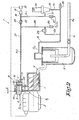
- Figures 1 and 2 represent a screw-type compressor 1 which is driven by a thermal, motor 2 and which is provided with an inlet 3 for drawing in a gas to be compressed and with an outlet 4 onto which is connected a pressure vessel 5.
- compressed gas under a certain operating pressure P w is drawn off to be used in all sorts of applications, such as for example to drive pneumatic hammers, or to feed a compressed air line, etc.
- an improved device 7 according to the invention is further provided.
- This improved device 7 mainly consists of a pneumatically controlled inlet valve 8 which is provided on the inlet 3 of the screw-type compressor 1 and which is formed of a housing 9 in which a valve element 10 can be shifted to and fro in the axial direction AA' between an open position, whereby the inlet opening D is maximal and is equal to D max , as is represented in figure 1 , and a closed position, whereby the inlet opening D is equal to 0, as is represented in figure 2 .
- This valve element 10 is sealed on one side 11, in particular on the side opposite the inlet 3, so as to form a pressure chamber 12.
- valve element 10 is usually pushed in the open position by a compression spring, no compression spring is provided in the device 7 according to the invention, and the valve element 10 without compression spring can thus freely move in the housing 9.
- valve element 10 is provided with a collar 13 on its free end on the side of the inlet 3.
- the improved device 7 further has a control valve 14 with an input 15 which is connected to the pressure vessel 5 via a pressure pipe 16, whereby, through this control valve 14, a control pressure P r1 is supplied to an output 17 as a function of the operating pressure P w at its input 15.
- a control pressure P r1 is built up at the output 17 of the control valve 14 which increases in proportion to the rising operating pressure P w .
- said threshold value A for the operating pressure amounts to 20 bar.
- control pressure P r1 is guided from the output 17 of the control valve 14 up to a pressure sensor 19.
- This pressure sensor 19 transforms the control pressure P r1 into an electric signal which is sent to an electronic speed controller 20 for adjusting the rotational speed N of the thermal motor 2.
- the electronic speed controller 20 is such that, as the control pressure P r1 rises, the motor 2 is set at a lower rotational speed, as is schematically represented in figure 4 , whereby the rotational speed N of the thermal motor 2 is represented as a function of the control pressure P r1 .
- the motor is adjusted between a maximum and a minimum rotational speed, represented in figure 4 by N max and N min respectively.
- the output 17 of the control valve 14 is also connected to the above-mentioned pressure chamber 12 at the inlet valve 8 via a second control line 21, in which is also provided a non-return valve 22 which is actuated by means of a spring 23 and which is pushed open when the control pressure P r1 behind the control valve 14 is sufficient to overcome the force of the spring 23.
- the force which is required to compress the spring 23 of the non-return valve 22 makes sure that the threshold value B of the operating pressure at which a control pressure P r2 is guided to the pressure chamber 12 is somewhat higher than the threshold value A of the operating pressure at which a control pressure P r1 is created.
- this threshold value B of the operating pressure is 20.6 bar.
- control pressure P r2 behind the non-return valve 22 for controlling the inlet valve 8 is also schematically represented in figure 3 as a function of the operating pressure P w , and it appears to be somewhat smaller than the control pressure P r1 available on the output 17 of the control valve 14 and which is used as the control pressure P r1 of the electronic speed controller 20.
- another bypass line 24 is provided between the pressure pipe 16 on the pressure vessel 5 and the second control line 21, in particular in the part 20 of the control line 21 between the inlet valve 8 and the non-return valve 22, whereby in this bypass line 24 is provided a cutoff valve or what is called a load valve 25 which is normally closed.
- This load valve 25 is an electromagnetic valve which may be open or closed, depending on whether the terminal clamps of said load valve 25 are either or not live.
- the bypass line 24 makes it possible to subject the pressure chamber 12 directly to the operating pressure P w in the pressure vessel 5, so that the working of the control valve 14 and of the non-return valve 22 is short-circuited.
- bypass line 24, both control lines 18 and 21, as well as the pressure pipe 16 are respectively provided with throttled blow-off openings 26, 27 and 28 which make it possible to drain off any condensed water.
- valve element 10 When starting the screw-type compressor 1, the valve element 10 is normally in the closed position, as is represented in figure 2 , since, when the screw-type compressor 1 was stopped during any preceding use, the operating pressure P w of the pressure vessel 5 was guided to the pressure chamber 12 via the bypass line 24, so that under this operating pressure P w , the valve element 10 was put in the closed position.
- valve element 10 can be moved in the horizontal or practically horizontal direction in the housing 9 of the valve element 10, after the screw-type compressor 1 has been stopped, the gravitational force will not have any influence on the position of the valve element 10, and the valve element 10 will stay in its closed position.
- the load valve 25 in the bypass line 24 is opened by means of an electric signal, such that the operating pressure P w which is built up in the pressure vessel 5 by the screw-type compressor 1 is guided via the control line 21 to the pressure chamber 12 behind the valve element 10.
- the non-return valve 22 prevents the operating pressure P w from being guided to the first control line 18 and the pressure sensor 19.
- the electric signal with which the load valve 25 is opened is also used to bridge the electronic speed controller 20, whereby one makes sure that the rotational speed N of the thermal motor 2 is set at its minimum value N min .
- This operating pressure P w which is guided to the pressure chamber 12 behind the valve element 10 will provide for the necessary counterpressure so as to compensate for the force on the collar 13 of the valve element 10 resulting from the difference in pressure P atm - P 0 , so that the valve element 10 will stay in its closed position during start up until the screw-type compressor 1 has reached its minimal rotational speed N min .
- the operating pressure P w in the pressure vessel 5 will gradually rise, at least as long as the supply of compressed gas is larger than the discharge thereof via the outlet pipe 6.
- control valve 14 will supply a control pressure P r1 at its output 17 which rises in proportion to the rising operating pressure P w .
- This control pressure P r1 via control line 18, reaches the pressure sensor 19 which sends an electric signal to the electronic speed controller 20 by which the rotational speed N of the motor 2 is adjusted, as is represented in figure 4 , whereby at a rising control pressure P r1 , the rotational speed N is set at increasingly lower values until, as soon as the control pressure P r1 exceeds a value C, the minimum value N min is reached.
- the flow rate supplied by the screw-type compressor 1 is geared to the flow rate taken via the outlet pipe 6, at least as far as the above-mentioned flow rates are situated within certain limits, whereby a balance between both flow rates can be created at any random rotational speed N between N max and N min .
- control pressure P r1 is directed to the spring-actuated non-return valve 22 via the control line 21 as well.
- Opening the spring 23 of the non-return valve 22 requires, as is represented in figure 4 , a certain control pressure E which in this case amounts to 0.6 bar.
- valve element 10 will move in the direction of the arrow P to a position which is more and more closed, as a result of which the flow rate through the screw-type compressor 1 is further restricted.
- valve element When the control pressure P r2 in the pressure chamber 12 rises to 1 bar, the valve element will entirely seal the inlet 3 of the screw-type compressor 1.
- the pre-stress of the spring 23 of the non-return valve 22 is such that the non-return valve 22 opens at a control pressure E which is somewhat lower than the control pressure C, whereby the above-mentioned electronic speed controller 20 sets the motor 2 at its minimum rotational speed N min .
- this control pressure E at which the non-return valve 22 opens is 0.6 bar
- the control pressure C at which the speed controller 20 sets the motor 2 at its minimum rotational speed N min is about 0.7 bar.
- the flow rate through the screw-type compressor 1 is first restricted by reducing the rotational speed N of the motor 2, as a result of which less fuel is consumed, and only then, when the motor is practically turning at its minimal rotational speed N min , the flow rate through the screw-type compressor 1 is further restricted by closing the inlet valve 8.
- This small overlap provides for a smooth transition between both adjustments, and in a general manner it makes sure that the flow rate of the screw-type compressor can be adjusted in a sliding manner.
Landscapes
- Engineering & Computer Science (AREA)
- Mechanical Engineering (AREA)
- General Engineering & Computer Science (AREA)
- Physics & Mathematics (AREA)
- Fluid Mechanics (AREA)
- Applications Or Details Of Rotary Compressors (AREA)
Claims (9)
- Dispositif perfectionné (7) pour régler le débit d'un compresseur à vis mobile (1) du type à injection d'huile qui est entraîné par un moteur thermique (2), ce compresseur (1) étant muni d'une entrée (3) et d'une sortie (4) à laquelle est raccordé un récipient de pression (5) comprenant un tuyau de sortie (6) pour l'alimentation de gaz comprimé, et ce dispositif (7) étant constitué principalement d'une vanne de commande (14) qui est raccordée au récipient de pression (5) avec son entrée (15) via un tuyau de pression (16) et qui alimente une pression de commande (Pr1) à sa sortie (17), à partir d'une certaine valeur préétablie de la pression (A) dans le tuyau de pression (16) du récipient de pression (5), qui est proportionnelle à ladite pression (Pw) dans le tuyau de pression (16) du récipient de pression (5) ; d'un régulateur de vitesse électronique (20) pour régler la vitesse de rotation (N) du moteur (2), qui est raccordé à la pression de commande susmentionné (Pr1) de la vanne de commande (14) via un capteur de pression (19) et une première ligne de commande (18), et qui est tel que, lorsque la pression de commande (Pr1) augmente, le moteur (2) est réglé à une vitesse de rotation inférieure (N) ; et d'un clapet d'admission (8) à commande pneumatique à l'entrée (3) du compresseur (1), ledit clapet d'admission (8) étant constitué d'un boîtier (9) dans lequel un élément faisant office de soupape (10) peut effectuer un mouvement alternatif dans la direction axiale (AA') entre une position ouverte et une position fermée, et qui est scellé d'un côté (11) de l'élément faisant office de soupape (10) de façon à former une chambre de pression (12) qui est raccordée via
une deuxième ligne de commande (21) à la pression de commande (Pr1) de la vanne de commande (14), caractérisé en ce que l'élément faisant office de soupape (10) peut se déplacer librement dans le boîtier (9), et en ce que, dans la ligne (21), qui relie la chambre de pression (12) du clapet d'admission (8) à la pression de commande (Pr1) de la vanne de commande (14), on prévoit un clapet de non-retour (22) actionné au moyen d'un ressort (23) qui peut être ouvert par poussée avec la pression de commande (Pr1). - Dispositif selon la revendication 1, caractérisé en ce que le clapet d'admission (8) est muni de moyens (24-26) qui maintiennent l'élément faisant office de soupape (10) dans sa position fermée au cours du démarrage.
- Dispositif selon la revendication 2, caractérisé en ce que les moyens susmentionnés (24-26) sont réalisés de telle sorte que l'on prévoit une ligne de déviation (24) entre le tuyau de pression (16) et la deuxième ligne de commande susmentionnée (21) du clapet d'admission (8), en particulier la partie de la ligne de commande (21) située entre le clapet d'admission (8) et le clapet de non-retour (22), une vanne de charge (25) étant prévue dans cette ligne de déviation (24), qui est normalement fermée, mais qui s'ouvre lorsque le compresseur (1) démarre.
- Dispositif selon l'une quelconque des revendications précédentes, caractérisé en ce que l'élément faisant office de soupape (10) peut se déplacer à l'intérieur du boîtier (9) du clapet d'admission (8) en direction horizontale ou en direction pratiquement horizontale.
- Dispositif selon l'une quelconque des revendications précédentes, caractérisé en ce que l'élément faisant office de soupape (10) est muni d'un col (13).
- Dispositif selon l'une quelconque des revendications précédentes, caractérisé en ce qu'on prévoit, dans la première ligne de commande (18), une ouverture de purge à étranglement (26) à laquelle le gaz comprimé dans cette ligne de commande (18) peut s'échapper dans l'atmosphère.
- Dispositif selon l'une quelconque des revendications 3 à 6, caractérisé en ce qu'on prévoit, dans la ligne de déviation (24), une ouverture de purge à étranglement (26).
- Dispositif selon l'une quelconque des revendications précédentes, caractérisé en ce qu'on prévoit, dans le tuyau de pression (16), avec lequel la vanne de commande (14) est reliée au récipient de pression (5), une ouverture de purge à étranglement (28).
- Dispositif selon l'une quelconque des revendications précédentes, caractérisé en ce que la précontrainte du ressort (23) du clapet de non-retour (22) est telle que le clapet de non-retour (22) s'ouvre à une pression de commande (E) qui est légèrement inférieure à la pression de commande (C), le régulateur de vitesse susmentionné (20) réglant le moteur (2) à sa vitesse de rotation minimale (Nmin).
Applications Claiming Priority (2)
| Application Number | Priority Date | Filing Date | Title |
|---|---|---|---|
| BE2005/0396A BE1016727A4 (nl) | 2005-08-17 | 2005-08-17 | Verbeterde inrichting voor het regelen van het debiet van een mobiele oliegeinjecteerde schroefcompressor. |
| PCT/BE2006/000087 WO2007019651A2 (fr) | 2005-08-17 | 2006-08-10 | Dispositif ameliore pour l'adaptation du debit d'un compresseur mobile de type a vis a injection d'huile |
Publications (2)
| Publication Number | Publication Date |
|---|---|
| EP1915535A2 EP1915535A2 (fr) | 2008-04-30 |
| EP1915535B1 true EP1915535B1 (fr) | 2015-10-07 |
Family
ID=36095723
Family Applications (1)
| Application Number | Title | Priority Date | Filing Date |
|---|---|---|---|
| EP06790451.6A Active EP1915535B1 (fr) | 2005-08-17 | 2006-08-10 | Dispositif ameliore pour l'adaptation du debit d'un compresseur mobile de type a vis a injection d'huile |
Country Status (6)
| Country | Link |
|---|---|
| US (1) | US8303264B2 (fr) |
| EP (1) | EP1915535B1 (fr) |
| BE (1) | BE1016727A4 (fr) |
| BR (1) | BRPI0614353B1 (fr) |
| ES (1) | ES2558945T3 (fr) |
| WO (1) | WO2007019651A2 (fr) |
Families Citing this family (11)
| Publication number | Priority date | Publication date | Assignee | Title |
|---|---|---|---|---|
| FR2915124B1 (fr) * | 2007-04-19 | 2010-02-26 | Sullair Europ | Dispositif de commande du moteur d'actionnement d'un systeme de compresseur de fluide gazeux et d'outil pneumatique associe et systeme obtenu. |
| JP5748106B2 (ja) * | 2011-06-03 | 2015-07-15 | アイシン精機株式会社 | 流体ポンプ |
| US10202968B2 (en) | 2012-08-30 | 2019-02-12 | Illinois Tool Works Inc. | Proportional air flow delivery control for a compressor |
| WO2016065431A1 (fr) * | 2014-10-29 | 2016-05-06 | Atlas Copco Airpower, Naamloze Vennootschap | Séparateur d'huile |
| BE1022569B1 (nl) * | 2014-10-29 | 2016-06-08 | Atlas Copco Airpower, Naamloze Vennootschap | Olieafscheider. |
| BE1022715B1 (nl) * | 2015-01-15 | 2016-08-23 | Atlas Copco Airpower Naamloze Vennootschap | Werkwijze voor het regelen van de snelheid van een compressor/vacuümpomp |
| EP4027016A1 (fr) * | 2015-01-15 | 2022-07-13 | ATLAS COPCO AIRPOWER, naamloze vennootschap | Procédé de réglage de la vitesse d'un compresseur/pompe à vide |
| CN107208641B (zh) * | 2015-01-15 | 2019-05-31 | 阿特拉斯·科普柯空气动力股份有限公司 | 用于控制压缩机/真空泵速度的方法 |
| DE102015111287B4 (de) * | 2015-07-13 | 2018-04-26 | Gardner Denver Deutschland Gmbh | Kompressor und Verfahren zu dessen Drehzahlsteuerung |
| US10775261B2 (en) * | 2018-02-12 | 2020-09-15 | Steering Solutions Ip Holding Corporation | In-vehicle seal integrity verification system |
| TWI795679B (zh) * | 2020-09-30 | 2023-03-11 | 復盛股份有限公司 | 螺旋式壓縮裝置及容積調控方法 |
Family Cites Families (6)
| Publication number | Priority date | Publication date | Assignee | Title |
|---|---|---|---|---|
| JPS58140498A (ja) * | 1982-02-17 | 1983-08-20 | Hitachi Ltd | スクリユ圧縮機の運転制御方法 |
| JPH0631627B2 (ja) * | 1984-07-25 | 1994-04-27 | 株式会社日立製作所 | 回転容積形真空ポンプ装置 |
| AT403948B (de) * | 1994-07-29 | 1998-06-25 | Hoerbiger Ventilwerke Ag | Ansaugregelventil für rotationsverdichter |
| BE1011782A3 (nl) * | 1998-03-10 | 2000-01-11 | Atlas Copco Airpower Nv | Compressoreenheid en daarbij gebruikte regelinrichting. |
| BE1013293A3 (nl) * | 2000-02-22 | 2001-11-06 | Atlas Copco Airpower Nv | Werkwijze voor het besturen van een compressorinstallatie en aldus bestuurde compressorinstallatie. |
| BE1015079A4 (nl) | 2002-08-22 | 2004-09-07 | Atlas Copco Airpower Nv | Compressor met drukontlasting. |
-
2005
- 2005-08-17 BE BE2005/0396A patent/BE1016727A4/nl not_active IP Right Cessation
-
2006
- 2006-08-10 EP EP06790451.6A patent/EP1915535B1/fr active Active
- 2006-08-10 WO PCT/BE2006/000087 patent/WO2007019651A2/fr not_active Ceased
- 2006-08-10 ES ES06790451.6T patent/ES2558945T3/es active Active
- 2006-08-10 BR BRPI0614353-9A patent/BRPI0614353B1/pt active IP Right Grant
- 2006-08-10 US US11/922,988 patent/US8303264B2/en active Active
Also Published As
| Publication number | Publication date |
|---|---|
| WO2007019651A3 (fr) | 2007-04-12 |
| EP1915535A2 (fr) | 2008-04-30 |
| US20100040487A1 (en) | 2010-02-18 |
| US8303264B2 (en) | 2012-11-06 |
| ES2558945T3 (es) | 2016-02-09 |
| BRPI0614353B1 (pt) | 2018-06-19 |
| BE1016727A4 (nl) | 2007-05-08 |
| BRPI0614353A2 (pt) | 2011-03-22 |
| WO2007019651A2 (fr) | 2007-02-22 |
Similar Documents
| Publication | Publication Date | Title |
|---|---|---|
| CN101163887B (zh) | 用于在停止期间控制变速压缩机的系统和方法 | |
| EP2027392B1 (fr) | Dispositif de régulation de la pression de fonctionnement pour poste de compression à injection d'huile | |
| EP1915535B1 (fr) | Dispositif ameliore pour l'adaptation du debit d'un compresseur mobile de type a vis a injection d'huile | |
| EP1937977B1 (fr) | Dispositif pour empecher la formation de condensat dans un gaz comprime et groupe compresseur equipe dudit dispositif | |
| EP3194784B1 (fr) | Procédé de commande d'un dispositif de compresseur à injection d'huile | |
| US12553436B2 (en) | Method for controlling a rotary screw compressor | |
| EP1552155B1 (fr) | Compresseur avec commande de capacite | |
| US20130039737A1 (en) | Method for controlling a compressor | |
| CN212028063U (zh) | 一种压缩机 | |
| EP1407147B1 (fr) | Compresseur a vis | |
| JP4532327B2 (ja) | 圧縮機およびその運転制御方法 | |
| JP4467409B2 (ja) | エンジン駆動型圧縮機の運転制御方法及びエンジン駆動型圧縮機 | |
| JPH01262389A (ja) | 圧縮機の運転制御方法 |
Legal Events
| Date | Code | Title | Description |
|---|---|---|---|
| PUAI | Public reference made under article 153(3) epc to a published international application that has entered the european phase |
Free format text: ORIGINAL CODE: 0009012 |
|
| 17P | Request for examination filed |
Effective date: 20071205 |
|
| AK | Designated contracting states |
Kind code of ref document: A2 Designated state(s): AT BE BG CH CY CZ DE DK EE ES FI FR GB GR HU IE IS IT LI LT LU LV MC NL PL PT RO SE SI SK TR |
|
| DAX | Request for extension of the european patent (deleted) | ||
| GRAP | Despatch of communication of intention to grant a patent |
Free format text: ORIGINAL CODE: EPIDOSNIGR1 |
|
| INTG | Intention to grant announced |
Effective date: 20150305 |
|
| GRAS | Grant fee paid |
Free format text: ORIGINAL CODE: EPIDOSNIGR3 |
|
| GRAF | Information related to payment of grant fee modified |
Free format text: ORIGINAL CODE: EPIDOSCIGR3 |
|
| GRAF | Information related to payment of grant fee modified |
Free format text: ORIGINAL CODE: EPIDOSCIGR3 |
|
| GRAA | (expected) grant |
Free format text: ORIGINAL CODE: 0009210 |
|
| AK | Designated contracting states |
Kind code of ref document: B1 Designated state(s): AT BE BG CH CY CZ DE DK EE ES FI FR GB GR HU IE IS IT LI LT LU LV MC NL PL PT RO SE SI SK TR |
|
| REG | Reference to a national code |
Ref country code: GB Ref legal event code: FG4D |
|
| REG | Reference to a national code |
Ref country code: AT Ref legal event code: REF Ref document number: 753929 Country of ref document: AT Kind code of ref document: T Effective date: 20151015 Ref country code: CH Ref legal event code: EP |
|
| REG | Reference to a national code |
Ref country code: IE Ref legal event code: FG4D |
|
| REG | Reference to a national code |
Ref country code: DE Ref legal event code: R096 Ref document number: 602006046878 Country of ref document: DE |
|
| REG | Reference to a national code |
Ref country code: SE Ref legal event code: TRGR |
|
| REG | Reference to a national code |
Ref country code: ES Ref legal event code: FG2A Ref document number: 2558945 Country of ref document: ES Kind code of ref document: T3 Effective date: 20160209 |
|
| REG | Reference to a national code |
Ref country code: NL Ref legal event code: MP Effective date: 20151007 |
|
| REG | Reference to a national code |
Ref country code: AT Ref legal event code: MK05 Ref document number: 753929 Country of ref document: AT Kind code of ref document: T Effective date: 20151007 |
|
| REG | Reference to a national code |
Ref country code: LT Ref legal event code: MG4D |
|
| PG25 | Lapsed in a contracting state [announced via postgrant information from national office to epo] |
Ref country code: IS Free format text: LAPSE BECAUSE OF FAILURE TO SUBMIT A TRANSLATION OF THE DESCRIPTION OR TO PAY THE FEE WITHIN THE PRESCRIBED TIME-LIMIT Effective date: 20160207 Ref country code: NL Free format text: LAPSE BECAUSE OF FAILURE TO SUBMIT A TRANSLATION OF THE DESCRIPTION OR TO PAY THE FEE WITHIN THE PRESCRIBED TIME-LIMIT Effective date: 20151007 Ref country code: LT Free format text: LAPSE BECAUSE OF FAILURE TO SUBMIT A TRANSLATION OF THE DESCRIPTION OR TO PAY THE FEE WITHIN THE PRESCRIBED TIME-LIMIT Effective date: 20151007 |
|
| PG25 | Lapsed in a contracting state [announced via postgrant information from national office to epo] |
Ref country code: PL Free format text: LAPSE BECAUSE OF FAILURE TO SUBMIT A TRANSLATION OF THE DESCRIPTION OR TO PAY THE FEE WITHIN THE PRESCRIBED TIME-LIMIT Effective date: 20151007 Ref country code: LV Free format text: LAPSE BECAUSE OF FAILURE TO SUBMIT A TRANSLATION OF THE DESCRIPTION OR TO PAY THE FEE WITHIN THE PRESCRIBED TIME-LIMIT Effective date: 20151007 Ref country code: AT Free format text: LAPSE BECAUSE OF FAILURE TO SUBMIT A TRANSLATION OF THE DESCRIPTION OR TO PAY THE FEE WITHIN THE PRESCRIBED TIME-LIMIT Effective date: 20151007 Ref country code: PT Free format text: LAPSE BECAUSE OF FAILURE TO SUBMIT A TRANSLATION OF THE DESCRIPTION OR TO PAY THE FEE WITHIN THE PRESCRIBED TIME-LIMIT Effective date: 20160208 Ref country code: GR Free format text: LAPSE BECAUSE OF FAILURE TO SUBMIT A TRANSLATION OF THE DESCRIPTION OR TO PAY THE FEE WITHIN THE PRESCRIBED TIME-LIMIT Effective date: 20160108 Ref country code: FI Free format text: LAPSE BECAUSE OF FAILURE TO SUBMIT A TRANSLATION OF THE DESCRIPTION OR TO PAY THE FEE WITHIN THE PRESCRIBED TIME-LIMIT Effective date: 20151007 |
|
| REG | Reference to a national code |
Ref country code: DE Ref legal event code: R097 Ref document number: 602006046878 Country of ref document: DE |
|
| PLBE | No opposition filed within time limit |
Free format text: ORIGINAL CODE: 0009261 |
|
| STAA | Information on the status of an ep patent application or granted ep patent |
Free format text: STATUS: NO OPPOSITION FILED WITHIN TIME LIMIT |
|
| REG | Reference to a national code |
Ref country code: FR Ref legal event code: PLFP Year of fee payment: 11 |
|
| PG25 | Lapsed in a contracting state [announced via postgrant information from national office to epo] |
Ref country code: EE Free format text: LAPSE BECAUSE OF FAILURE TO SUBMIT A TRANSLATION OF THE DESCRIPTION OR TO PAY THE FEE WITHIN THE PRESCRIBED TIME-LIMIT Effective date: 20151007 Ref country code: DK Free format text: LAPSE BECAUSE OF FAILURE TO SUBMIT A TRANSLATION OF THE DESCRIPTION OR TO PAY THE FEE WITHIN THE PRESCRIBED TIME-LIMIT Effective date: 20151007 Ref country code: RO Free format text: LAPSE BECAUSE OF FAILURE TO SUBMIT A TRANSLATION OF THE DESCRIPTION OR TO PAY THE FEE WITHIN THE PRESCRIBED TIME-LIMIT Effective date: 20151007 Ref country code: SK Free format text: LAPSE BECAUSE OF FAILURE TO SUBMIT A TRANSLATION OF THE DESCRIPTION OR TO PAY THE FEE WITHIN THE PRESCRIBED TIME-LIMIT Effective date: 20151007 |
|
| 26N | No opposition filed |
Effective date: 20160708 |
|
| PG25 | Lapsed in a contracting state [announced via postgrant information from national office to epo] |
Ref country code: SI Free format text: LAPSE BECAUSE OF FAILURE TO SUBMIT A TRANSLATION OF THE DESCRIPTION OR TO PAY THE FEE WITHIN THE PRESCRIBED TIME-LIMIT Effective date: 20151007 |
|
| PG25 | Lapsed in a contracting state [announced via postgrant information from national office to epo] |
Ref country code: MC Free format text: LAPSE BECAUSE OF FAILURE TO SUBMIT A TRANSLATION OF THE DESCRIPTION OR TO PAY THE FEE WITHIN THE PRESCRIBED TIME-LIMIT Effective date: 20151007 |
|
| REG | Reference to a national code |
Ref country code: CH Ref legal event code: PL |
|
| PG25 | Lapsed in a contracting state [announced via postgrant information from national office to epo] |
Ref country code: LI Free format text: LAPSE BECAUSE OF NON-PAYMENT OF DUE FEES Effective date: 20160831 Ref country code: CH Free format text: LAPSE BECAUSE OF NON-PAYMENT OF DUE FEES Effective date: 20160831 |
|
| REG | Reference to a national code |
Ref country code: IE Ref legal event code: MM4A |
|
| PG25 | Lapsed in a contracting state [announced via postgrant information from national office to epo] |
Ref country code: IE Free format text: LAPSE BECAUSE OF NON-PAYMENT OF DUE FEES Effective date: 20160810 |
|
| REG | Reference to a national code |
Ref country code: FR Ref legal event code: PLFP Year of fee payment: 12 |
|
| PG25 | Lapsed in a contracting state [announced via postgrant information from national office to epo] |
Ref country code: LU Free format text: LAPSE BECAUSE OF NON-PAYMENT OF DUE FEES Effective date: 20160810 |
|
| PG25 | Lapsed in a contracting state [announced via postgrant information from national office to epo] |
Ref country code: CY Free format text: LAPSE BECAUSE OF FAILURE TO SUBMIT A TRANSLATION OF THE DESCRIPTION OR TO PAY THE FEE WITHIN THE PRESCRIBED TIME-LIMIT Effective date: 20151007 Ref country code: HU Free format text: LAPSE BECAUSE OF FAILURE TO SUBMIT A TRANSLATION OF THE DESCRIPTION OR TO PAY THE FEE WITHIN THE PRESCRIBED TIME-LIMIT; INVALID AB INITIO Effective date: 20060810 |
|
| PG25 | Lapsed in a contracting state [announced via postgrant information from national office to epo] |
Ref country code: TR Free format text: LAPSE BECAUSE OF FAILURE TO SUBMIT A TRANSLATION OF THE DESCRIPTION OR TO PAY THE FEE WITHIN THE PRESCRIBED TIME-LIMIT Effective date: 20151007 |
|
| PG25 | Lapsed in a contracting state [announced via postgrant information from national office to epo] |
Ref country code: BG Free format text: LAPSE BECAUSE OF FAILURE TO SUBMIT A TRANSLATION OF THE DESCRIPTION OR TO PAY THE FEE WITHIN THE PRESCRIBED TIME-LIMIT Effective date: 20151007 |
|
| REG | Reference to a national code |
Ref country code: FR Ref legal event code: PLFP Year of fee payment: 13 |
|
| P01 | Opt-out of the competence of the unified patent court (upc) registered |
Effective date: 20230602 |
|
| PGFP | Annual fee paid to national office [announced via postgrant information from national office to epo] |
Ref country code: ES Payment date: 20250901 Year of fee payment: 20 |
|
| PGFP | Annual fee paid to national office [announced via postgrant information from national office to epo] |
Ref country code: DE Payment date: 20250827 Year of fee payment: 20 |
|
| PGFP | Annual fee paid to national office [announced via postgrant information from national office to epo] |
Ref country code: IT Payment date: 20250820 Year of fee payment: 20 |
|
| PGFP | Annual fee paid to national office [announced via postgrant information from national office to epo] |
Ref country code: BE Payment date: 20250827 Year of fee payment: 20 Ref country code: GB Payment date: 20250827 Year of fee payment: 20 |
|
| PGFP | Annual fee paid to national office [announced via postgrant information from national office to epo] |
Ref country code: FR Payment date: 20250825 Year of fee payment: 20 |
|
| PGFP | Annual fee paid to national office [announced via postgrant information from national office to epo] |
Ref country code: SE Payment date: 20250827 Year of fee payment: 20 |
|
| PGFP | Annual fee paid to national office [announced via postgrant information from national office to epo] |
Ref country code: CZ Payment date: 20250724 Year of fee payment: 20 |