EP1915599B1 - Sensoranordnung zur temperaturmessung - Google Patents
Sensoranordnung zur temperaturmessung Download PDFInfo
- Publication number
- EP1915599B1 EP1915599B1 EP06761725.8A EP06761725A EP1915599B1 EP 1915599 B1 EP1915599 B1 EP 1915599B1 EP 06761725 A EP06761725 A EP 06761725A EP 1915599 B1 EP1915599 B1 EP 1915599B1
- Authority
- EP
- European Patent Office
- Prior art keywords
- circuit carrier
- conducting element
- sensor
- sensor arrangement
- heat conducting
- Prior art date
- Legal status (The legal status is an assumption and is not a legal conclusion. Google has not performed a legal analysis and makes no representation as to the accuracy of the status listed.)
- Ceased
Links
Images
Classifications
-
- G—PHYSICS
- G01—MEASURING; TESTING
- G01K—MEASURING TEMPERATURE; MEASURING QUANTITY OF HEAT; THERMALLY-SENSITIVE ELEMENTS NOT OTHERWISE PROVIDED FOR
- G01K1/00—Details of thermometers not specially adapted for particular types of thermometer
- G01K1/14—Supports; Fastening devices; Arrangements for mounting thermometers in particular locations
-
- B—PERFORMING OPERATIONS; TRANSPORTING
- B60—VEHICLES IN GENERAL
- B60H—ARRANGEMENTS OF HEATING, COOLING, VENTILATING OR OTHER AIR-TREATING DEVICES SPECIALLY ADAPTED FOR PASSENGER OR GOODS SPACES OF VEHICLES
- B60H1/00—Heating, cooling or ventilating devices
- B60H1/00642—Control systems or circuits; Control members or indication devices for heating, cooling or ventilating devices
- B60H1/00735—Control systems or circuits characterised by their input, i.e. by the detection, measurement or calculation of particular conditions, e.g. signal treatment, dynamic models
- B60H1/00792—Arrangement of detectors
-
- B—PERFORMING OPERATIONS; TRANSPORTING
- B60—VEHICLES IN GENERAL
- B60H—ARRANGEMENTS OF HEATING, COOLING, VENTILATING OR OTHER AIR-TREATING DEVICES SPECIALLY ADAPTED FOR PASSENGER OR GOODS SPACES OF VEHICLES
- B60H1/00—Heating, cooling or ventilating devices
-
- G—PHYSICS
- G01—MEASURING; TESTING
- G01K—MEASURING TEMPERATURE; MEASURING QUANTITY OF HEAT; THERMALLY-SENSITIVE ELEMENTS NOT OTHERWISE PROVIDED FOR
- G01K1/00—Details of thermometers not specially adapted for particular types of thermometer
-
- G—PHYSICS
- G01—MEASURING; TESTING
- G01K—MEASURING TEMPERATURE; MEASURING QUANTITY OF HEAT; THERMALLY-SENSITIVE ELEMENTS NOT OTHERWISE PROVIDED FOR
- G01K1/00—Details of thermometers not specially adapted for particular types of thermometer
- G01K1/14—Supports; Fastening devices; Arrangements for mounting thermometers in particular locations
- G01K1/143—Supports; Fastening devices; Arrangements for mounting thermometers in particular locations for measuring surface temperatures
Definitions
- the invention relates to a sensor arrangement for measuring the temperature of a surface.
- Such sensor arrangements preferably for the temperature measurement of approximately planar surfaces, are variously known.
- a surface temperature sensor is known in which a heat-conducting surface contact part is pressed by means of a spring against the surface to be measured.
- the surface contact part contains an electrically isolated mounted temperature sensor.
- the DE 102 14 368 A1 discloses a surface temperature sensor for a battery cell.
- the temperature sensor of DE'368 can be connected to the surface of the battery cell by means of a flexible heat-conducting element.
- the invention has for its object to provide a cost-effective sensor arrangement, with which the temperature of an approximately flat surface, in particular a disc can be detected.
- the sensor arrangement according to the invention for measuring the temperature of a surface has a temperature sensor mounted on a circuit carrier, which is positioned in the region of an end side of the circuit carrier in the immediate vicinity of the surface, wherein a flexible heat conducting element is mounted between the surface and the circuit carrier.
- the mounting of the temperature sensor directly on the circuit board reduces the cost of the sensor arrangement, since no additional fasteners are needed.
- the circuit carrier is connected by a heat conducting element with the surface in connection, wherein the end face of the circuit carrier is preferably aligned approximately parallel to the surface. As a result, the heat can be transferred from the surface to the circuit carrier and from there to the temperature sensor.
- the heat-conducting element is designed to be flexible, so that it can absorb mechanical stresses, whereby damage to the circuit carrier or the temperature sensor during installation or removal or operation can be avoided.
- the flexible heat-conducting element has a front side in contact with the surface to be measured and a side which is in contact with the circuit carrier in a planar manner.
- the front side of the flexible heat-conducting element is preferably designed with a smooth surface that is rounded off at least at the edges. This allows the sensor assembly to slide along the surface to be measured can be moved or rotated, which is particularly advantageous when installing or removing the sensor assembly, for example, when the circuit carrier is fastened by means of a bayonet closure.
- the flexible heat-conducting element consists of a good heat-conducting metal, in particular copper or aluminum or alloy, in particular brass or bronze.
- the flexible heat-conducting element can transmit the heat particularly well to the circuit carrier.
- heat conductors made of these materials are particularly inexpensive to produce.
- the heat-conducting element has a resilient element. This is fixed at one end to the housing and ensures a pressure of the front of the heat conductor to the surface to be measured.
- the circuit carrier and the heat-conducting element are pressed against one another flatly.
- the force is chosen in particular so that the Circuit carrier and the heat conductor are intimately adjacent to each other and at the same time a displacement of the heat conductor is possible against the circuit carrier.
- the circuit carrier is metallized on the front side and / or on the opposite side of the temperature sensor and / or on the side surfaces.
- the metallization ensures good thermal conductivity.
- the metallization can in this case simultaneously serve the electrical contacting of the temperature sensor.
- the metallization of the front side can be connected to a terminal of the temperature sensor.
- plated-through holes are provided in the circuit carrier in the vicinity of the temperature sensor. These are for usually designed as metallized holes through the circuit substrate and serve the electrical and thermal connection of the temperature sensor with the underside of the circuit substrate to which a preferably planar metallization is attached in this case.
- an evaluation unit is additionally mounted on the circuit carrier, so that a common assembly can be used both for measurement and for evaluation.
- a further temperature sensor which approximately determines the temperature of the sensor housing or the interior, is located on the circuit carrier in the immediate vicinity of the surface to be measured.
- the measured value of the temperature sensor which is located in the immediate vicinity of the surface to be measured and whose measured value corresponds to the temperature of the surface to be measured, with the Measured value of the second temperature sensor corrected.
- further sensors in particular temperature sensors, humidity sensors or light sensors, are mounted on the circuit carrier.
- the circuit carrier is preferably mounted in the interior of a motor vehicle and serves to measure the temperature of the windshield.
- it can preferably be integrated into a rearview mirror base as a housing.
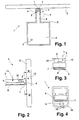
- FIG. 1 is a sensor assembly 1 for measuring temperature on a nearly flat, formed by the windshield 2 of a motor vehicle surface.
- the sensor arrangement 1 has a temperature sensor 3 which is mounted on a circuit carrier 4 in FIG is arranged in the immediate vicinity of a front side 4 'of the circuit substrate 4.
- the front side 4 ' runs parallel to the surface of the windshield 2 along a tongue-shaped projection of the circuit substrate 4 and is positioned in the immediate vicinity of the surface of the windshield 2.
- the circuit carrier 4 is enclosed by a housing 5 which is fastened to a rear-view mirror, not shown in the figure, of a rear-view mirror of the motor vehicle.
- the housing 5 has an opening in the region of the projection 6.
- a flexible, heat-conducting element 7 is attached between the circuit substrate 4 and the surface of the windscreen 2, a flexible, heat-conducting element 7 is attached.
- the flexible, L-shaped heat-conducting element 7 is on the one hand connected to the circuit carrier 4 and on the other hand abuts against the surface of the front pane 2.
- the system is resiliently formed by means of spring elements 8 , so that the element 7 is applied in the direction of arrow 9 on the surface of the windshield 2 pressurized. This allows a damage-free pressing of the sensor assembly 1 to the surface of the windshield 2 in a direction perpendicular to the surface of the windscreen 2 Direction so that the temperature sensor 3 can be arranged at a defined distance from the surface of the windshield 2.
- the flexible heat-conducting element 7 is shaped in such a way that its contact surface with the surface of the front pane 2 is at its maximum or that the air gap between the heat-conducting element 7 and the surface of the front pane 2 is minimal. As a result, a good thermal coupling between the surface of the windshield 2 and the flexible heat conducting element 7 is given, which ensures that the flexible heat conducting element 7 has almost the same temperature as the surface of the windshield 2.
- the heat-conducting element 7 may be formed such that it rests on one or more points on the surface of the windshield 2 almost point-like. As a result, the thermal coupling to the surface of the windscreen 2 is slightly reduced, but production-related, ie varying from disc to disc surface irregularities do not lead to a varying thermal coupling.
- the heat-conducting element 7 is made of metal, preferably copper or aluminum, or an alloy, preferably brass.
- the heat-conducting element 7 and the circuit carrier 4 are pressed flat against one another in the region of the temperature sensor 3.
- the required force is supplied by a resilient element which is formed as a plastic tongues 10 with the housing. These generate a force in the direction of arrow 11, which on the one hand is large enough to produce a strong contact between the circuit substrate 4 and the heat-conducting element 7.
- the force is chosen so that the frictional force between the circuit carrier 4 and the heat-conducting element 7 is smaller than the spring force of the tongues 10, so that the heat-conducting element 7 is movable perpendicular to the surface of the windshield 2 according to double arrow 12 .
- the circuit carrier 4 is metallized in the region of the end face 4 ', on the underside and the side surfaces. This results in a particularly good heat conduction between the circuit carrier 4 and the heat conducting element 7 ensured.
- One of the electrical contacts of the temperature sensor 3 is electrically conductively connected to the end face of the circuit substrate 4. Alternatively, the electrical contact can also be connected via plated-through holes to the underside of the circuit carrier 4. As a result, the temperature of the temperature sensor 3 can be adapted particularly well to the temperature of the heat-conducting element 7.
- the sensor arrangement shown in the figures allows attachment by means of a bayonet closure, since the robust heat conducting element 7 ensures that a displacement or rotation of the sensor arrangement along the surface of the windshield 2 usually does not lead to damage thereof.
- the further sensors may include a temperature sensor 3 'for measuring the temperature of the interior and an air humidity sensor.
- the two other sensors can be used together with the temperature sensor for Measurement of the surface temperature can be used to determine the fogging of the windscreen.
- FIG. 4 (analogous to FIG. 3 ) may be formed on the circuit substrate 4, the resilient, pressurized system of thedaleleitelements 7 alternatively by means of an elastic housing membrane 13 .
- a pin 14 is pressed against the underside of the heat-conducting element 7 in the direction of arrow 15 .
Landscapes
- Physics & Mathematics (AREA)
- General Physics & Mathematics (AREA)
- Thermal Sciences (AREA)
- Engineering & Computer Science (AREA)
- Mechanical Engineering (AREA)
- Measuring Temperature Or Quantity Of Heat (AREA)
Description
- Die Erfindung betrifft eine Sensoranordnung zur Messung der Temperatur einer Oberfläche.
- Derartige Sensoranordnungen, vorzugsweise zur Temperaturmessung von näherungsweise planen Oberflächen, sind verschiedentlich bekannt.
- Aus der
DE 699 07 493 T2 ist ein Oberflächentemperaturfühler bekannt, bei dem ein Wärme leitendes Oberflächenkontaktteil mit Hilfe einer Feder gegen die zu messende Oberfläche gedrückt wird. Das Oberflächenkontaktteil enthält einen elektrisch isoliert angebrachten Temperatursensor. - Aus der
DE 102 27 454 A1 ist ein Anlegetemperaturfühler bekannt, bei dem ein Anlegeteil mit Hilfe einer Wärmeleitfolie und Wärmeleitpaste thermisch leitend an die zu messende Oberfläche angebunden ist. An das Anlegteil ist mit Hilfe einer weiteren Wärmeleitfolie ein Temperatursensor angekoppelt. - Die
DE 102 14 368 A1 offenbart einen Oberflächentemperatursensor für eine Akku-Zelle. Der Temperatursensor der DE'368 ist mittels eines flexiblen Wärmeleitelement mit der Oberfläche der Akku-Zelle verbindbar. - Der Erfindung liegt die Aufgabe zugrunde, eine kostengünstige Sensoranordnung zu schaffen, mit der die Temperatur einer näherungsweise ebenen Oberfläche, insbesondere einer Scheibe, erfasst werden kann.
- Diese Aufgabe wird erfindungsgemäß durch die Sensoranordnung des Anspruchs 1 gelöst. Die abhängigen Ansprüche stellen bevorzugte Ausführungsformen der Erfindung dar.
- Die erfindungsgemäße Sensoranordnung zur Temperaturmessung einer Oberfläche weist einen auf einem Schaltungsträger angebrachten Temperatursensor auf, der im Bereich einer Stirnseite des Schaltungsträgers in unmittelbarer Nähe zu der Oberfläche positioniert ist, wobei zwischen der Oberfläche und dem Schaltungsträger ein flexibles Wärmeleitelement angebracht ist.
- Die Anbringung des Temperatursensors unmittelbar auf dem Schaltungsträger reduziert die Kosten der Sensoranordnung, da keine zusätzlichen Verbindungselemente benötigt werden. Der Schaltungsträger steht durch ein Wärmeleitelement mit der Oberfläche in Verbindung, wobei die Stirnseite des Schaltungsträgers bevorzugt näherungsweise parallel zur Oberfläche ausgerichtet ist. Dadurch kann die Wärme von der Oberfläche auf den Schaltungsträger und von dort auf den Temperatursensor übertragen werden. Das Wärmeleitelement ist flexibel ausgelegt, sodass es mechanische Beanspruchungen aufnehmen kann, wodurch eine Beschädigung des Schaltungsträgers oder des Temperatursensors beim Ein- oder Ausbau oder dem Betrieb vermieden werden kann.
- In einer besonders bevorzugten Ausführungsform weist das flexible Wärmeleitelement eine mit der zu messenden Oberfläche in Kontakt stehende Vorderseite und eine mit dem Schaltungsträger flächig in Kontakt stehende Seite auf.
- Die Vorderseite des flexiblen Wärmeleitelements ist bevorzugt mit einer glatten und zumindest an den Rändern abgerundeten Oberfläche ausgeführt. Dadurch ermöglicht sie es, dass die Sensoranordnung entlang der zu messenden Oberfläche gleitend verschoben bzw. gedreht werden kann, was insbesondere beim Ein- oder Ausbau der Sensoranordnung von Vorteil ist, z.B. wenn der Schaltungsträger mittels eines Bajonettverschlusses befestigt wird.
- In einer bevorzugten Weiterbildung besteht das flexible Wärmeleitelement aus einem gut Wärme leitenden Metall, insbesondere Kupfer oder Aluminium oder Legierung, insbesondere Messing oder Bronze. Das flexible Wärmeleitelement kann in diesem Fall die Wärme besonders gut auf den Schaltungsträger übertragen. Außerdem sind Wärmeleiter aus diesen Materialien besonders kostengünstig herzustellen.
- In einer besonders bevorzugten Weiterbildung weist das Wärmeleitelement ein federndes Element auf. Dieses ist an einem Ende am Gehäuse fixiert und sorgt für einen Andruck der Vorderseite des Wärmeleiters an die zu messende Oberfläche.
- In einer weiteren bevorzugten Weiterbildung werden der Schaltungsträger und das Wärmeleitelement flächig aneinander gedrückt. Die Kraft wird dabei insbesondere so gewählt, dass der Schaltungsträger und der Wärmeleiter innig aneinander liegen und gleichzeitig ein Verschieben des Wärmeleiters gegen den Schaltungsträger möglich ist.
- In einer weiteren vorteilhaften Weiterbildung wird der Andruck zwischen Schaltungsträger und Wärmeleiter durch ein federndes Element, das sich im Sensorgehäuse befindet oder von diesem ausgebildet ist, erzeugt.
- In einer besonders bevorzugten Ausführungsform ist der Schaltungsträger an der Stirnseite und/oder an der dem Temperatursensor gegenüberliegenden Seite und/oder an den Seitenflächen metallisiert. Durch die Metallisierung wird eine gute Wärmeleitfähigkeit sichergestellt. Die Metallisierung kann hierbei gleichzeitig der elektrischen Kontaktierung des Temperatursensors dienen. Insbesondere kann hierzu die Metallisierung der Stirnseite mit einem Anschluss des Temperatursensors verbunden sein.
- In einer Weiterbildung sind in dem Schaltungsträger in der Nähe des Temperatursensors Durchkontaktierungen angebracht. Diese sind für gewöhnlich als metallisierte Bohrungen durch den Schaltungsträger ausgeführt und dienen der elektrischen sowie thermischen Verbindung des Temperatursensors mit der Unterseite des Schaltungsträgers, an der in diesem Fall eine bevorzugt flächige Metallisierung angebracht ist.
- In einer bevorzugten Ausführungsform ist auf dem Schaltungsträger zusätzlich eine Auswerteeinheit angebracht, sodass eine gemeinsame Baugruppe sowohl zur Messung als auch zur Auswertung eingesetzt werden kann.
- In einer weiteren vorteilhaften Weiterbildung befindet sich auf dem Schaltungsträger in nicht unmittelbarer Nähe der zu messenden Oberfläche ein weiterer Temperatursensor, der näherungsweise die Temperatur des Sensorgehäuses oder des Innenraums ermittelt.
- In einer weiteren besonders vorteilhaften Weiterbildung wird der Messwert des Temperatursensors, der sich in unmittelbarer Nähe der zu messenden Oberfläche befindet und dessen Messwert der Temperatur der zu messenden Oberfläche entspricht, mit dem Messwert des zweiten Temperatursensors korrigiert. Dadurch kann der endliche Wärmeleitwert des Wärmeleiters und des Schaltungsträgers ausgeglichen werden.
- In einer weiteren bevorzugten Ausführungsform sind auf dem Schaltungsträger weitere Sensoren, insbesondere Temperatursensoren, Feuchtesensoren oder Lichtsensoren, angebracht. Der Schaltungsträger ist in diesem Fall bevorzugt im Innenraum eines Kraftfahrzeugs angebracht und dient zur Messung der Temperatur der Frontscheibe. Hierzu kann sie bevorzugt in einen Rückspiegelfuß als Gehäuse integriert werden. Durch eine gleichzeitige Messung der Temperatur der Scheibenoberfläche, des Innenraumes sowie der Luftfeuchte mit den entsprechenden Sensoren kann die Sensoranordnung beispielsweise zur Messung des Scheibenbeschlags eingesetzt werden.
- Weitere Vorteile ergeben sich aus der Beschreibung und den Zeichnungen. Die vorstehend genannten und die noch weiter aufgeführten Merkmale können jeweils einzeln oder in Kombination verwendet werden. Die erwähnten Ausführungsformen sind nicht als abschließende Aufzählung zu verstehen, sondern haben vielmehr beispielhaften Charakter.
- Zwei Ausführungsbeispiele der Erfindung sind in der schematischen Zeichnung dargestellt und werden nachfolgend anhand der Figuren der Zeichnung näher erläutert. Es zeigt:
- Figur 1
- eine Aufsicht einer ersten Sensoranordnung;
- Figur 2
- eine Seitenansicht der Sensoranordnung nach
Figur 1 ; - Figur 3
- einen Schnitt durch die Sensoranordnung nach
Figur 2 gemäß III-III; - Figur 4
- einen Schnitt durch eine zweite Sensoranordnung.
- In
Figur 1 ist eine Sensoranordnung 1 zur Temperaturmessung an einer nahezu planen, durch die Frontscheibe 2 eines Kraftfahrzeugs gebildeten Oberfläche gezeigt. Die Sensoranordnung 1 weist einen Temperatursensor 3 auf, der auf einem Schaltungsträger 4 in unmittelbarer Nähe zu einer Stirnseite 4' des Schaltungsträgers 4 angeordnet ist. Die Stirnseite 4' verläuft parallel zur Oberfläche der Frontscheibe 2 entlang eines zungenförmigen Vorsprungs des Schaltungsträgers 4 und ist in unmittelbarer Nähe der Oberfläche der Frontscheibe 2 positioniert. Der Schaltungsträger 4 ist von einem Gehäuse 5 umschlossen, welches an einem in der Figur nicht gezeigten Rückspiegelfuß eines Rückspiegels des Kraftfahrzeugs befestigt wird. Das Gehäuse 5 weist im Bereich des Vorsprungs 6 eine Öffnung auf. - Zwischen dem Schaltungsträger 4 und der Oberfläche der Frontscheibe 2 ist ein flexibles, Wärme leitendes Element 7 angebracht. Das flexible, L-förmige Wärme leitende Element 7 ist einerseits mit dem Schaltungsträger 4 verbunden und liegt andererseits an der Oberfläche der Frontscheibe 2 an. Die Anlage ist mithilfe von Federelementen 8 federnd ausgebildet, so dass das Element 7 in Pfeilrichtung 9 an der Oberfläche der Frontscheibe 2 druckbeaufschlagt anliegt. Dies ermöglicht ein beschädigungsfreies Anpressen der Sensoranordnung 1 an die Oberfläche der Frontscheibe 2 in einer senkrecht zur Oberfläche der Frontscheibe 2 verlaufenden Richtung, sodass der Temperatursensor 3 in einem definierten Abstand zur Oberfläche der Frontscheibe 2 angeordnet werden kann. Das flexible Wärmeleitelement 7 ist so ausgeformt, dass seine Kontaktfläche mit der Oberfläche der Frontscheibe 2 maximal bzw. dass der Luftspalt zwischen dem Wärmeleitelement 7 und der Oberfläche der Frontscheibe 2 minimal ist. Dadurch ist eine gute thermische Kopplung zwischen der Oberfläche der Frontscheibe 2 und dem flexiblen Wärmeleitelement 7 gegeben, die sicherstellt, dass das flexible Wärmeleitelement 7 nahezu die gleiche Temperatur wie die Oberfläche der Frontscheibe 2 aufweist.
- Alternativ kann das Wärmeleitelement 7 so ausgeformt sein, dass es nahezu punktförmig an einem oder mehreren Punkten auf der Oberfläche der Frontscheibe 2 aufliegt. Dadurch wird die thermische Kopplung zur Oberfläche der Frontscheibe 2 geringfügig vermindert, aber fertigungsbedingte, d.h. von Scheibe zu Scheibe variierende Unebenheiten der Oberfläche führen nicht zu einer variierenden thermischen Kopplung.
- Das Wärmeleitelement 7 ist aus Metall, bevorzugt aus Kupfer oder Aluminium, oder einer Legierung, bevorzugt Messing, hergestellt.
- Gemäß
Figur 2 und Figur 3 werden das Wärmeleitelement 7 und der Schaltungsträger 4 im Bereich des Temperatursensors 3 flächig aneinander gedrückt. Die dazu erforderliche Kraft wird von einem federnden Element geliefert, das als Kunststoffzungen 10 mit am Gehäuse ausgeformt ist. Diese erzeugen eine Kraft in Pfeilrichtung 11, die einerseits groß genug ist, um einen starken Kontakt zwischen dem Schaltungsträger 4 und dem Wärmeleitelement 7 zu erzeugen. Andererseits ist die Kraft so gewählt, dass die Reibungskraft zwischen dem Schaltungsträger 4 und dem Wärmeleitelement 7 kleiner ist als die Federkraft der Zungen 10, so dass das Wärmeleitelement 7 senkrecht zur Oberfläche der Frontscheibe 2 gemäß Doppelpfeil 12 beweglich ist. - Der Schaltungsträger 4 ist im Bereich der Stirnfläche 4', an der Unterseite sowie den Seitenflächen metallisiert. Hierdurch wird eine besonders gute Wärmeleitung zwischen dem Schaltungsträger 4 und dem Wärmeleitelement 7 sichergestellt. Einer der elektrischen Kontakte des Temperatursensors 3 ist mit der Stirnfläche des Schaltungsträgers 4 elektrisch leitend verbunden. Alternativ kann der elektrische Kontakt auch über Durchkontaktierungen mit der Unterseite des Schaltungsträgers 4 verbunden sein. Hierdurch kann die Temperatur des Temperatursensors 3 besonders gut an die Temperatur des Wärmeleitelements 7 angeglichen werden.
- Die in den Figuren gezeigte Sensoranordnung ermöglicht eine Befestigung mittels eines Bajonettverschlusses, da das robuste Wärmeleitelement 7 sicher stellt, dass eine Verschiebung oder Drehung der Sensoranordnung entlang der Oberfläche der Frontscheibe 2 im Regelfall nicht zu einer Beschädigung derselben führt.
- Auf dem Schaltungsträger 4 können weitere Sensoren sowie eine Auswerteeinheit angebracht sein. Die weiteren Sensoren können einen Temperatursensor 3' zur Messung der Temperatur des Innenraums sowie einen Luftfeuchtesensor umfassen. Die zwei weiteren Sensoren können zusammen mit dem Temperatursensor zur Messung der Oberflächentemperatur für die Bestimmung der Beschlagsneigung der Frontscheibe eingesetzt werden.
- Gemäß
Figur 4 (analog zuFigur 3 ) kann die federnde, druckbeaufschlagte Anlage des Wärmeleitelements 7 an dem Schaltungsträger 4 alternativ auch mithilfe einer elastischen Gehäusemembran 13 ausgebildet sein. Mithilfe der Gehäusemembran 13 wird ein Stift 14 gegen die Unterseite des Wärmeleitelements 7 in Pfeilrichtung 15 gedrückt.
Claims (10)
- Sensoranordnung (1) zur Temperaturmessung der Oberfläche einer Scheibe (2), mit einem auf einem Schaltungsträger (4) angebrachten Temperatursensor (3), mit einem Sensorgehäuse (5) sowie mit der Scheibe (2) mit der zu messenden Oberfläche, wobei der Temperatursensor im Bereich einer Stirnseite (4') des Schaltungsträgers (4) in unmittelbarer Nähe zu der zu messenden Oberfläche positioniert ist, wobei zwischen der zu messenden Oberfläche und dem Schaltungsträger (4) ein flexibles Wärmeleitelement (7) angebracht ist, wobei das Wärmeleitelement (7) und der Schaltungsträger (4) im Bereich des Temperatursensors (3) flächig aneinander gedrückt sind, und wobei der Andruck zwischen dem Schaltungsträger (4) und dem Wärmeleitelement (7) durch ein federndes Element, das sich im Sensorgehäuse (5) befindet oder von diesem ausgebildet ist, erzeugt wird.
- Sensoranordnung nach Anspruch 1, dadurch gekennzeichnet, dass das flexible Wärmeleitelement (7) L-förmig ausgebildet ist und einen mit der zu messenden Oberfläche in Kontakt stehenden Schenkel und einen mit dem Schaltungsträger flächig in Kontakt stehenden Schenkel aufweist.
- Sensoranordnung nach Anspruch 2, dadurch gekennzeichnet, dass die der Oberfläche zugeordnete Vorderseite des flexiblen Wärmeleitelements (7) eine glatte Oberfläche aufweist und zumindest an den Rändern abgerundet ist.
- Sensoranordnung nach Ansprüchen 2 oder 3, dadurch gekennzeichnet, dass das flexible Wärmeleitelement (7) aus einem Wärme leitenden Metall, insbesondere Kupfer oder Aluminium, oder einer Legierung, insbesondere Messing oder Bronze, besteht.
- Sensoranordnung nach Anspruch 2 bis 4, dadurch gekennzeichnet, dass Mittel (8) zur federnden Anlage des flexiblen Wärmeleitelements (7) an der Oberfläche vorgesehen sind.
- Sensoranordnung nach einem der Ansprüche 2 bis 5, dadurch gekennzeichnet, dass der Schaltungsträger (4) und das flexible Wärmeleitelement (7) im Bereich des Temperatursensors (3) flächig aneinander anliegen.
- Sensoranordnung nach einem der vorhergehenden Ansprüche, dadurch gekennzeichnet, dass das Wärmeleitelement (7) in Richtung (12) der Oberfläche verschiebbar angeordnet ist.
- Sensoranordnung nach einem der vorhergehenden Ansprüche, dadurch gekennzeichnet, dass der Schaltungsträger (4) zusätzlich zu den Leiterbahnen für den Temperatursensor (3) an der Stirnseite (4') und/oder an der dem Temperatursensor (3) gegenüberliegenden Seite und/oder an den Seitenflächen metallisiert ist.
- Sensoranordnung nach Anspruch 8, dadurch gekennzeichnet, dass in dem Schaltungsträger (4) in der Nähe des Temperatursensors (3) Durchkontaktierungen angebracht sind.
- Sensoranordnung nach einem der vorhergehenden Ansprüche, dadurch gekennzeichnet, dass auf dem Schaltungsträger (4) zusätzlich eine Auswerteeinheit angebracht ist.
Applications Claiming Priority (2)
| Application Number | Priority Date | Filing Date | Title |
|---|---|---|---|
| DE102005038466A DE102005038466B4 (de) | 2005-08-13 | 2005-08-13 | Sensoranordnung zur Temperaturmessung |
| PCT/DE2006/001121 WO2007019817A1 (de) | 2005-08-13 | 2006-06-29 | Sensoranordnung zur temperaturmessung |
Publications (2)
| Publication Number | Publication Date |
|---|---|
| EP1915599A1 EP1915599A1 (de) | 2008-04-30 |
| EP1915599B1 true EP1915599B1 (de) | 2016-11-23 |
Family
ID=37192504
Family Applications (1)
| Application Number | Title | Priority Date | Filing Date |
|---|---|---|---|
| EP06761725.8A Ceased EP1915599B1 (de) | 2005-08-13 | 2006-06-29 | Sensoranordnung zur temperaturmessung |
Country Status (6)
| Country | Link |
|---|---|
| US (1) | US8162539B2 (de) |
| EP (1) | EP1915599B1 (de) |
| JP (1) | JP5153630B2 (de) |
| KR (1) | KR20080042836A (de) |
| DE (1) | DE102005038466B4 (de) |
| WO (1) | WO2007019817A1 (de) |
Families Citing this family (13)
| Publication number | Priority date | Publication date | Assignee | Title |
|---|---|---|---|---|
| US7511501B2 (en) * | 2007-05-11 | 2009-03-31 | General Electric Company | Systems and apparatus for monitoring internal temperature of a gradient coil |
| DE102007026842A1 (de) * | 2007-06-06 | 2008-12-11 | Endress + Hauser Wetzer Gmbh + Co Kg | Vorrichtung zur Bestimmung und/oder Überwachung einer Messgröße |
| GB0909525D0 (en) * | 2009-06-03 | 2009-07-15 | Rwr Systems Ltd | Sensor assembly and a method of sensing |
| US8905635B2 (en) * | 2011-09-30 | 2014-12-09 | Honeywell International Inc. | Temperature sensor attachment facilitating thermal conductivity to a measurement point and insulation from a surrounding environment |
| US10018514B2 (en) * | 2014-02-17 | 2018-07-10 | Haier Us Appliance Solutions, Inc. | Cooktop temperature sensors and methods of operation |
| GB2526247B (en) | 2014-03-12 | 2018-12-05 | Rtl Mat Ltd | Methods and apparatus relating to deployment of fibre optic assemblies by burial. |
| EP3769060B1 (de) | 2018-03-23 | 2025-03-12 | Watlow Electric Manufacturing Company | Temperaturdetektorsonde mit thermischer isolierung |
| DE102018122940B4 (de) | 2018-09-19 | 2026-04-09 | HELLA GmbH & Co. KGaA | Sensoranordnung zur Messung der Temperatur einer Scheibe |
| DE102018008986A1 (de) * | 2018-11-15 | 2020-05-20 | Diehl Ako Stiftung & Co. Kg | Temperaturerfassungsvorrichtung |
| EP3660475B1 (de) * | 2018-11-28 | 2022-08-10 | General Electric Company | Systeme und verfahren zur thermischen überwachung |
| KR102192548B1 (ko) * | 2019-03-04 | 2020-12-17 | 암페놀센싱코리아 유한회사 | 차량용 배터리 온도센서 |
| EP3800452B1 (de) * | 2019-10-04 | 2021-12-15 | MEAS France | Temperatursensorvorrichtung für eine windschutzscheibe eines fahrzeugs |
| DE102021120159A1 (de) * | 2021-08-03 | 2023-02-09 | HELLA GmbH & Co. KGaA | Sensorvorrichtung zur Erfassung der Temperatur an einem flächigen Bauteil, insbesondere an einer Scheibe eines Fahrzeuges |
Family Cites Families (20)
| Publication number | Priority date | Publication date | Assignee | Title |
|---|---|---|---|---|
| GB2208930B (en) * | 1987-08-19 | 1991-11-27 | Xerox Corp | Temperature sensor |
| GB2233457A (en) * | 1989-06-21 | 1991-01-09 | Schlumberger Technologies Ltd | Temperature reference junction for a multichannel temperature sensing system. |
| JPH0545234A (ja) | 1991-08-20 | 1993-02-23 | Matsushita Electric Ind Co Ltd | 温度センサ |
| JP3481748B2 (ja) | 1995-10-23 | 2003-12-22 | 株式会社リコー | 定着装置 |
| JPH09210802A (ja) * | 1996-02-02 | 1997-08-15 | Sharp Corp | 表面実装用温度検出素子 |
| DE19816941A1 (de) * | 1998-04-16 | 1999-10-21 | Viessmann Werke Kg | Temperatursensor und Verfahren zu seiner Herstellung |
| US6257758B1 (en) * | 1998-10-09 | 2001-07-10 | Claud S. Gordon Company | Surface temperature sensor |
| DE10104942A1 (de) | 2000-02-11 | 2001-08-16 | E & E Elektronik Gmbh | Sensoranordnung |
| US6573704B2 (en) * | 2000-12-21 | 2003-06-03 | Sun Microsystems, Inc. | Method and apparatus for isolating an ambient air temperature sensor |
| DE10152999C2 (de) | 2001-10-26 | 2003-12-24 | Preh Elektro Feinmechanik | Sensor und Sensoreinheit zur Detektion einer Beschlagneigung |
| DE10227454A1 (de) * | 2001-11-12 | 2003-05-22 | Temperaturmestechnik Geraberg | Verfahren zur Temperaturmessung sowie Anlegetemperaturfühler |
| DE10214368B4 (de) | 2002-03-30 | 2007-09-13 | Robert Bosch Gmbh | Energiespeichermodul und dessen Verwendung für ein Elektrogerät |
| JP3815362B2 (ja) * | 2002-04-08 | 2006-08-30 | 株式会社村田製作所 | 温度検出素子およびこれを備える回路基板 |
| JP3857638B2 (ja) | 2002-11-13 | 2006-12-13 | 本田技研工業株式会社 | 当接式温度測定装置 |
| US7197927B2 (en) * | 2004-02-16 | 2007-04-03 | Sitronic Gesellschaft für Elektrotechnische Ausrustüng mbH & Co. KG | Sensor for determining the interior humidity and fogging up tendency and fastening device of the sensor |
| DE102005016896B3 (de) | 2005-04-12 | 2006-10-26 | Sitronic Gesellschaft für elektrotechnische Ausrüstung mbH. & Co. KG | Sensoranordnung zur Temperaturmessung |
| US7784173B2 (en) * | 2005-12-27 | 2010-08-31 | Palo Alto Research Center Incorporated | Producing layered structures using printing |
| US7513686B2 (en) * | 2006-02-27 | 2009-04-07 | Advanced Micro Devices, Inc. | Circuit lid with a thermocouple |
| US8794827B2 (en) * | 2009-02-02 | 2014-08-05 | Yazaki Corporation | Thermal sensing structure and insulating structure of thermal sensing circuit |
| US8360636B2 (en) * | 2009-07-02 | 2013-01-29 | Renesas Electronics America Inc. | Temperature detection and reporting system and method in power driving and/or consuming system |
-
2005
- 2005-08-13 DE DE102005038466A patent/DE102005038466B4/de not_active Expired - Fee Related
-
2006
- 2006-06-29 WO PCT/DE2006/001121 patent/WO2007019817A1/de not_active Ceased
- 2006-06-29 EP EP06761725.8A patent/EP1915599B1/de not_active Ceased
- 2006-06-29 US US11/990,420 patent/US8162539B2/en not_active Expired - Fee Related
- 2006-06-29 KR KR1020087003944A patent/KR20080042836A/ko not_active Withdrawn
- 2006-06-29 JP JP2008525373A patent/JP5153630B2/ja not_active Expired - Fee Related
Also Published As
| Publication number | Publication date |
|---|---|
| DE102005038466B4 (de) | 2007-12-13 |
| JP5153630B2 (ja) | 2013-02-27 |
| KR20080042836A (ko) | 2008-05-15 |
| US20090316751A1 (en) | 2009-12-24 |
| JP2009505042A (ja) | 2009-02-05 |
| US8162539B2 (en) | 2012-04-24 |
| DE102005038466A1 (de) | 2007-04-12 |
| EP1915599A1 (de) | 2008-04-30 |
| WO2007019817A1 (de) | 2007-02-22 |
Similar Documents
| Publication | Publication Date | Title |
|---|---|---|
| EP1875180B1 (de) | Sensoranordnung zur temperaturmessung | |
| EP1915599B1 (de) | Sensoranordnung zur temperaturmessung | |
| EP1936342A1 (de) | Sensoranordnung zur Temperaturmessung | |
| DE19856663C2 (de) | Kontaktvorrichtung für ein an einer Fensterscheibe angeordnetes elektrisches Funktionselement | |
| EP1257443B1 (de) | Sensoranordnung | |
| EP2341326B1 (de) | Heizkostenverteiler | |
| EP1966011A2 (de) | Kapazitiver regensensor | |
| DE102018122940B4 (de) | Sensoranordnung zur Messung der Temperatur einer Scheibe | |
| EP3451790B1 (de) | Vorrichtung mit beheizbarer streulichtblende | |
| EP3615903A1 (de) | Sensor zur erfassung eines räumlichen temperaturprofils und verfahren zur herstellung einer sensoreinheit | |
| DE102010030769B4 (de) | Temperaturfühler zur Messung einer Fahrzeuginnentemperatur | |
| DE102004023989B3 (de) | Elektronischer Heizkostenverteiler | |
| EP1077366B2 (de) | Elektronischer Heizkostenverteiler | |
| DE10111371A1 (de) | Felxible Flachbandleitung und Verfahren zum Anschluss eines elektrischen Funktionsbauteils an eine flexible Flachbandleitung | |
| DE102018113230A1 (de) | Sensormodul | |
| EP1598224B1 (de) | Vorrichtung zur Ermittlung von Beschlag auf einer Fläche eines Fahrzeuges | |
| EP1683665B1 (de) | Sensoranordnung | |
| DE102009048940B3 (de) | Heizkostenverteiler | |
| DE102007016536B4 (de) | Vorrichtung zur Messung eines in einem Druckmedium herrschenden Drucks | |
| WO1996004536A1 (de) | Temperatursensor | |
| DE10157113A1 (de) | Elektronische Baugruppe | |
| DE102009005294A1 (de) | Verfahren zur Befestigung einer Fenterscheibe eines Kraftfahrzeuges und HF-Anordnung | |
| DE202010018197U1 (de) | Heizkostenverteiler | |
| DE202014003413U1 (de) | Vorrichtung zum elektronischen Erfassen der Wärmeabgabe eines Heizkörpers |
Legal Events
| Date | Code | Title | Description |
|---|---|---|---|
| PUAI | Public reference made under article 153(3) epc to a published international application that has entered the european phase |
Free format text: ORIGINAL CODE: 0009012 |
|
| 17P | Request for examination filed |
Effective date: 20080313 |
|
| AK | Designated contracting states |
Kind code of ref document: A1 Designated state(s): CZ ES FR HU IT SE |
|
| RBV | Designated contracting states (corrected) |
Designated state(s): CZ ES FR HU IT SE |
|
| 17Q | First examination report despatched |
Effective date: 20101222 |
|
| DAX | Request for extension of the european patent (deleted) | ||
| GRAP | Despatch of communication of intention to grant a patent |
Free format text: ORIGINAL CODE: EPIDOSNIGR1 |
|
| INTG | Intention to grant announced |
Effective date: 20160616 |
|
| GRAS | Grant fee paid |
Free format text: ORIGINAL CODE: EPIDOSNIGR3 |
|
| GRAA | (expected) grant |
Free format text: ORIGINAL CODE: 0009210 |
|
| AK | Designated contracting states |
Kind code of ref document: B1 Designated state(s): CZ ES FR HU IT SE |
|
| PG25 | Lapsed in a contracting state [announced via postgrant information from national office to epo] |
Ref country code: SE Free format text: LAPSE BECAUSE OF FAILURE TO SUBMIT A TRANSLATION OF THE DESCRIPTION OR TO PAY THE FEE WITHIN THE PRESCRIBED TIME-LIMIT Effective date: 20161123 |
|
| PG25 | Lapsed in a contracting state [announced via postgrant information from national office to epo] |
Ref country code: ES Free format text: LAPSE BECAUSE OF FAILURE TO SUBMIT A TRANSLATION OF THE DESCRIPTION OR TO PAY THE FEE WITHIN THE PRESCRIBED TIME-LIMIT Effective date: 20161123 |
|
| REG | Reference to a national code |
Ref country code: FR Ref legal event code: PLFP Year of fee payment: 12 |
|
| PG25 | Lapsed in a contracting state [announced via postgrant information from national office to epo] |
Ref country code: CZ Free format text: LAPSE BECAUSE OF FAILURE TO SUBMIT A TRANSLATION OF THE DESCRIPTION OR TO PAY THE FEE WITHIN THE PRESCRIBED TIME-LIMIT Effective date: 20161123 |
|
| PGFP | Annual fee paid to national office [announced via postgrant information from national office to epo] |
Ref country code: FR Payment date: 20170621 Year of fee payment: 12 |
|
| PGFP | Annual fee paid to national office [announced via postgrant information from national office to epo] |
Ref country code: IT Payment date: 20170622 Year of fee payment: 12 |
|
| PLBE | No opposition filed within time limit |
Free format text: ORIGINAL CODE: 0009261 |
|
| STAA | Information on the status of an ep patent application or granted ep patent |
Free format text: STATUS: NO OPPOSITION FILED WITHIN TIME LIMIT |
|
| 26N | No opposition filed |
Effective date: 20170824 |
|
| PG25 | Lapsed in a contracting state [announced via postgrant information from national office to epo] |
Ref country code: FR Free format text: LAPSE BECAUSE OF NON-PAYMENT OF DUE FEES Effective date: 20180630 Ref country code: IT Free format text: LAPSE BECAUSE OF NON-PAYMENT OF DUE FEES Effective date: 20180629 |
|
| PG25 | Lapsed in a contracting state [announced via postgrant information from national office to epo] |
Ref country code: HU Free format text: LAPSE BECAUSE OF FAILURE TO SUBMIT A TRANSLATION OF THE DESCRIPTION OR TO PAY THE FEE WITHIN THE PRESCRIBED TIME-LIMIT; INVALID AB INITIO Effective date: 20060629 |