EP1915599B1 - Dispositif de detection pour mesurer la temperature - Google Patents
Dispositif de detection pour mesurer la temperature Download PDFInfo
- Publication number
- EP1915599B1 EP1915599B1 EP06761725.8A EP06761725A EP1915599B1 EP 1915599 B1 EP1915599 B1 EP 1915599B1 EP 06761725 A EP06761725 A EP 06761725A EP 1915599 B1 EP1915599 B1 EP 1915599B1
- Authority
- EP
- European Patent Office
- Prior art keywords
- circuit carrier
- conducting element
- sensor
- sensor arrangement
- heat conducting
- Prior art date
- Legal status (The legal status is an assumption and is not a legal conclusion. Google has not performed a legal analysis and makes no representation as to the accuracy of the status listed.)
- Ceased
Links
Images
Classifications
-
- G—PHYSICS
- G01—MEASURING; TESTING
- G01K—MEASURING TEMPERATURE; MEASURING QUANTITY OF HEAT; THERMALLY-SENSITIVE ELEMENTS NOT OTHERWISE PROVIDED FOR
- G01K1/00—Details of thermometers not specially adapted for particular types of thermometer
- G01K1/14—Supports; Fastening devices; Arrangements for mounting thermometers in particular locations
-
- B—PERFORMING OPERATIONS; TRANSPORTING
- B60—VEHICLES IN GENERAL
- B60H—ARRANGEMENTS OF HEATING, COOLING, VENTILATING OR OTHER AIR-TREATING DEVICES SPECIALLY ADAPTED FOR PASSENGER OR GOODS SPACES OF VEHICLES
- B60H1/00—Heating, cooling or ventilating devices
- B60H1/00642—Control systems or circuits; Control members or indication devices for heating, cooling or ventilating devices
- B60H1/00735—Control systems or circuits characterised by their input, i.e. by the detection, measurement or calculation of particular conditions, e.g. signal treatment, dynamic models
- B60H1/00792—Arrangement of detectors
-
- B—PERFORMING OPERATIONS; TRANSPORTING
- B60—VEHICLES IN GENERAL
- B60H—ARRANGEMENTS OF HEATING, COOLING, VENTILATING OR OTHER AIR-TREATING DEVICES SPECIALLY ADAPTED FOR PASSENGER OR GOODS SPACES OF VEHICLES
- B60H1/00—Heating, cooling or ventilating devices
-
- G—PHYSICS
- G01—MEASURING; TESTING
- G01K—MEASURING TEMPERATURE; MEASURING QUANTITY OF HEAT; THERMALLY-SENSITIVE ELEMENTS NOT OTHERWISE PROVIDED FOR
- G01K1/00—Details of thermometers not specially adapted for particular types of thermometer
-
- G—PHYSICS
- G01—MEASURING; TESTING
- G01K—MEASURING TEMPERATURE; MEASURING QUANTITY OF HEAT; THERMALLY-SENSITIVE ELEMENTS NOT OTHERWISE PROVIDED FOR
- G01K1/00—Details of thermometers not specially adapted for particular types of thermometer
- G01K1/14—Supports; Fastening devices; Arrangements for mounting thermometers in particular locations
- G01K1/143—Supports; Fastening devices; Arrangements for mounting thermometers in particular locations for measuring surface temperatures
Definitions
- the invention relates to a sensor arrangement for measuring the temperature of a surface.
- Such sensor arrangements preferably for the temperature measurement of approximately planar surfaces, are variously known.
- a surface temperature sensor is known in which a heat-conducting surface contact part is pressed by means of a spring against the surface to be measured.
- the surface contact part contains an electrically isolated mounted temperature sensor.
- the DE 102 14 368 A1 discloses a surface temperature sensor for a battery cell.
- the temperature sensor of DE'368 can be connected to the surface of the battery cell by means of a flexible heat-conducting element.
- the invention has for its object to provide a cost-effective sensor arrangement, with which the temperature of an approximately flat surface, in particular a disc can be detected.
- the sensor arrangement according to the invention for measuring the temperature of a surface has a temperature sensor mounted on a circuit carrier, which is positioned in the region of an end side of the circuit carrier in the immediate vicinity of the surface, wherein a flexible heat conducting element is mounted between the surface and the circuit carrier.
- the mounting of the temperature sensor directly on the circuit board reduces the cost of the sensor arrangement, since no additional fasteners are needed.
- the circuit carrier is connected by a heat conducting element with the surface in connection, wherein the end face of the circuit carrier is preferably aligned approximately parallel to the surface. As a result, the heat can be transferred from the surface to the circuit carrier and from there to the temperature sensor.
- the heat-conducting element is designed to be flexible, so that it can absorb mechanical stresses, whereby damage to the circuit carrier or the temperature sensor during installation or removal or operation can be avoided.
- the flexible heat-conducting element has a front side in contact with the surface to be measured and a side which is in contact with the circuit carrier in a planar manner.
- the front side of the flexible heat-conducting element is preferably designed with a smooth surface that is rounded off at least at the edges. This allows the sensor assembly to slide along the surface to be measured can be moved or rotated, which is particularly advantageous when installing or removing the sensor assembly, for example, when the circuit carrier is fastened by means of a bayonet closure.
- the flexible heat-conducting element consists of a good heat-conducting metal, in particular copper or aluminum or alloy, in particular brass or bronze.
- the flexible heat-conducting element can transmit the heat particularly well to the circuit carrier.
- heat conductors made of these materials are particularly inexpensive to produce.
- the heat-conducting element has a resilient element. This is fixed at one end to the housing and ensures a pressure of the front of the heat conductor to the surface to be measured.
- the circuit carrier and the heat-conducting element are pressed against one another flatly.
- the force is chosen in particular so that the Circuit carrier and the heat conductor are intimately adjacent to each other and at the same time a displacement of the heat conductor is possible against the circuit carrier.
- the circuit carrier is metallized on the front side and / or on the opposite side of the temperature sensor and / or on the side surfaces.
- the metallization ensures good thermal conductivity.
- the metallization can in this case simultaneously serve the electrical contacting of the temperature sensor.
- the metallization of the front side can be connected to a terminal of the temperature sensor.
- plated-through holes are provided in the circuit carrier in the vicinity of the temperature sensor. These are for usually designed as metallized holes through the circuit substrate and serve the electrical and thermal connection of the temperature sensor with the underside of the circuit substrate to which a preferably planar metallization is attached in this case.
- an evaluation unit is additionally mounted on the circuit carrier, so that a common assembly can be used both for measurement and for evaluation.
- a further temperature sensor which approximately determines the temperature of the sensor housing or the interior, is located on the circuit carrier in the immediate vicinity of the surface to be measured.
- the measured value of the temperature sensor which is located in the immediate vicinity of the surface to be measured and whose measured value corresponds to the temperature of the surface to be measured, with the Measured value of the second temperature sensor corrected.
- further sensors in particular temperature sensors, humidity sensors or light sensors, are mounted on the circuit carrier.
- the circuit carrier is preferably mounted in the interior of a motor vehicle and serves to measure the temperature of the windshield.
- it can preferably be integrated into a rearview mirror base as a housing.
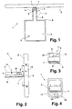
- FIG. 1 is a sensor assembly 1 for measuring temperature on a nearly flat, formed by the windshield 2 of a motor vehicle surface.
- the sensor arrangement 1 has a temperature sensor 3 which is mounted on a circuit carrier 4 in FIG is arranged in the immediate vicinity of a front side 4 'of the circuit substrate 4.
- the front side 4 ' runs parallel to the surface of the windshield 2 along a tongue-shaped projection of the circuit substrate 4 and is positioned in the immediate vicinity of the surface of the windshield 2.
- the circuit carrier 4 is enclosed by a housing 5 which is fastened to a rear-view mirror, not shown in the figure, of a rear-view mirror of the motor vehicle.
- the housing 5 has an opening in the region of the projection 6.
- a flexible, heat-conducting element 7 is attached between the circuit substrate 4 and the surface of the windscreen 2, a flexible, heat-conducting element 7 is attached.
- the flexible, L-shaped heat-conducting element 7 is on the one hand connected to the circuit carrier 4 and on the other hand abuts against the surface of the front pane 2.
- the system is resiliently formed by means of spring elements 8 , so that the element 7 is applied in the direction of arrow 9 on the surface of the windshield 2 pressurized. This allows a damage-free pressing of the sensor assembly 1 to the surface of the windshield 2 in a direction perpendicular to the surface of the windscreen 2 Direction so that the temperature sensor 3 can be arranged at a defined distance from the surface of the windshield 2.
- the flexible heat-conducting element 7 is shaped in such a way that its contact surface with the surface of the front pane 2 is at its maximum or that the air gap between the heat-conducting element 7 and the surface of the front pane 2 is minimal. As a result, a good thermal coupling between the surface of the windshield 2 and the flexible heat conducting element 7 is given, which ensures that the flexible heat conducting element 7 has almost the same temperature as the surface of the windshield 2.
- the heat-conducting element 7 may be formed such that it rests on one or more points on the surface of the windshield 2 almost point-like. As a result, the thermal coupling to the surface of the windscreen 2 is slightly reduced, but production-related, ie varying from disc to disc surface irregularities do not lead to a varying thermal coupling.
- the heat-conducting element 7 is made of metal, preferably copper or aluminum, or an alloy, preferably brass.
- the heat-conducting element 7 and the circuit carrier 4 are pressed flat against one another in the region of the temperature sensor 3.
- the required force is supplied by a resilient element which is formed as a plastic tongues 10 with the housing. These generate a force in the direction of arrow 11, which on the one hand is large enough to produce a strong contact between the circuit substrate 4 and the heat-conducting element 7.
- the force is chosen so that the frictional force between the circuit carrier 4 and the heat-conducting element 7 is smaller than the spring force of the tongues 10, so that the heat-conducting element 7 is movable perpendicular to the surface of the windshield 2 according to double arrow 12 .
- the circuit carrier 4 is metallized in the region of the end face 4 ', on the underside and the side surfaces. This results in a particularly good heat conduction between the circuit carrier 4 and the heat conducting element 7 ensured.
- One of the electrical contacts of the temperature sensor 3 is electrically conductively connected to the end face of the circuit substrate 4. Alternatively, the electrical contact can also be connected via plated-through holes to the underside of the circuit carrier 4. As a result, the temperature of the temperature sensor 3 can be adapted particularly well to the temperature of the heat-conducting element 7.
- the sensor arrangement shown in the figures allows attachment by means of a bayonet closure, since the robust heat conducting element 7 ensures that a displacement or rotation of the sensor arrangement along the surface of the windshield 2 usually does not lead to damage thereof.
- the further sensors may include a temperature sensor 3 'for measuring the temperature of the interior and an air humidity sensor.
- the two other sensors can be used together with the temperature sensor for Measurement of the surface temperature can be used to determine the fogging of the windscreen.
- FIG. 4 (analogous to FIG. 3 ) may be formed on the circuit substrate 4, the resilient, pressurized system of thedaleleitelements 7 alternatively by means of an elastic housing membrane 13 .
- a pin 14 is pressed against the underside of the heat-conducting element 7 in the direction of arrow 15 .
Landscapes
- Physics & Mathematics (AREA)
- General Physics & Mathematics (AREA)
- Thermal Sciences (AREA)
- Engineering & Computer Science (AREA)
- Mechanical Engineering (AREA)
- Measuring Temperature Or Quantity Of Heat (AREA)
Claims (10)
- Dispositif de détection (1) pour mesurer la température de la surface d'une vitre (2), avec un capteur de température (3) disposé sur un support de circuit (4), avec un boîtier de capteur (5) ainsi qu'avec la vitre (2) présentant la surface à mesurer, le capteur de température étant positionné dans la zone d'une face frontale (4') du support de circuit (4) à proximité immédiate de la surface à mesurer, un élément thermoconducteur flexible (7) étant disposé entre la surface à mesurer et le support de circuit (4), l'élément thermoconducteur (7) et le support de circuit (4) étant pressés à plat l'un contre l'autre dans la zone du capteur de température (3) et la pression d'application entre le support de circuit (4) et l'élément thermoconducteur (7) étant produite par un élément faisant ressort qui se trouve dans le boîtier de capteur (5) ou qui est formé par celui-ci.
- Dispositif de détection selon la revendication 1, caractérisé en ce que l'élément thermoconducteur flexible (7) est réalisé en forme de L et présente une branche en contact avec la surface à mesurer et une branche en contact plan avec le support de circuit.
- Dispositif de détection selon la revendication 2, caractérisé en ce que la face avant de l'élément thermoconducteur flexible (7) associée à la surface présente une surface lisse et est arrondie au moins aux bords.
- Dispositif de détection selon les revendications 2 ou 3, caractérisé en ce que l'élément thermoconducteur flexible (7) est constitué d'un métal conducteur de la chaleur, en particulier de cuivre ou d'aluminium, ou d'un alliage, en particulier de laiton ou de bronze.
- Dispositif de détection selon les revendications 2 à 4, caractérisé en ce que des moyens (8) pour l'appui élastique de l'élément thermoconducteur (7) sont prévus á la surface.
- Dispositif de détection selon l'une des revendications 2 à 5, caractérisé en ce que le support de circuit (4) et l'élément thermoconducteur flexible (7) sont en appui plan l'un contre l'autre dans la zone du capteur de température (3).
- Dispositif de détection selon l'une des revendications précédentes, caractérisé en ce que l'élément thermoconducteur (7) est disposé de façon à pouvoir coulisser en direction (12) de la surface.
- Dispositif de détection selon l'une des revendications précédentes, caractérisé en ce que le support de circuit (4), en plus des pistes conductrices pour le capteur de température (3), est métallisé sur la face frontale (4') et/ou sur la face opposée au capteur de température (3) et/ou sur les faces latérales.
- Dispositif de détection selon la revendication 8, caractérisé en ce que des trous métallisés sont réalisés dans le support de circuit (4) à proximité du capteur de température (3).
- Dispositif de détection selon l'une des revendications précédentes, caractérisé en ce qu'une unité d'évaluation est disposée en plus sur le support de circuit (4).
Applications Claiming Priority (2)
| Application Number | Priority Date | Filing Date | Title |
|---|---|---|---|
| DE102005038466A DE102005038466B4 (de) | 2005-08-13 | 2005-08-13 | Sensoranordnung zur Temperaturmessung |
| PCT/DE2006/001121 WO2007019817A1 (fr) | 2005-08-13 | 2006-06-29 | Dispositif de detection pour mesurer la temperature |
Publications (2)
| Publication Number | Publication Date |
|---|---|
| EP1915599A1 EP1915599A1 (fr) | 2008-04-30 |
| EP1915599B1 true EP1915599B1 (fr) | 2016-11-23 |
Family
ID=37192504
Family Applications (1)
| Application Number | Title | Priority Date | Filing Date |
|---|---|---|---|
| EP06761725.8A Ceased EP1915599B1 (fr) | 2005-08-13 | 2006-06-29 | Dispositif de detection pour mesurer la temperature |
Country Status (6)
| Country | Link |
|---|---|
| US (1) | US8162539B2 (fr) |
| EP (1) | EP1915599B1 (fr) |
| JP (1) | JP5153630B2 (fr) |
| KR (1) | KR20080042836A (fr) |
| DE (1) | DE102005038466B4 (fr) |
| WO (1) | WO2007019817A1 (fr) |
Families Citing this family (13)
| Publication number | Priority date | Publication date | Assignee | Title |
|---|---|---|---|---|
| US7511501B2 (en) * | 2007-05-11 | 2009-03-31 | General Electric Company | Systems and apparatus for monitoring internal temperature of a gradient coil |
| DE102007026842A1 (de) * | 2007-06-06 | 2008-12-11 | Endress + Hauser Wetzer Gmbh + Co Kg | Vorrichtung zur Bestimmung und/oder Überwachung einer Messgröße |
| GB0909525D0 (en) | 2009-06-03 | 2009-07-15 | Rwr Systems Ltd | Sensor assembly and a method of sensing |
| US8905635B2 (en) * | 2011-09-30 | 2014-12-09 | Honeywell International Inc. | Temperature sensor attachment facilitating thermal conductivity to a measurement point and insulation from a surrounding environment |
| US10018514B2 (en) * | 2014-02-17 | 2018-07-10 | Haier Us Appliance Solutions, Inc. | Cooktop temperature sensors and methods of operation |
| GB2526247B (en) | 2014-03-12 | 2018-12-05 | Rtl Mat Ltd | Methods and apparatus relating to deployment of fibre optic assemblies by burial. |
| WO2019183353A1 (fr) | 2018-03-23 | 2019-09-26 | Watlow Electric Manufacturing Company | Sonde de détecteur de température à isolation thermique |
| DE102018122940B4 (de) | 2018-09-19 | 2026-04-09 | HELLA GmbH & Co. KGaA | Sensoranordnung zur Messung der Temperatur einer Scheibe |
| DE102018008986A1 (de) * | 2018-11-15 | 2020-05-20 | Diehl Ako Stiftung & Co. Kg | Temperaturerfassungsvorrichtung |
| EP3660475B1 (fr) * | 2018-11-28 | 2022-08-10 | General Electric Company | Systèmes et procédés de surveillance thermique |
| KR102192548B1 (ko) * | 2019-03-04 | 2020-12-17 | 암페놀센싱코리아 유한회사 | 차량용 배터리 온도센서 |
| EP3800452B1 (fr) * | 2019-10-04 | 2021-12-15 | MEAS France | Dispositif capteur de température pour pare-brise de véhicule |
| DE102021120159A1 (de) * | 2021-08-03 | 2023-02-09 | HELLA GmbH & Co. KGaA | Sensorvorrichtung zur Erfassung der Temperatur an einem flächigen Bauteil, insbesondere an einer Scheibe eines Fahrzeuges |
Family Cites Families (20)
| Publication number | Priority date | Publication date | Assignee | Title |
|---|---|---|---|---|
| GB2208930B (en) * | 1987-08-19 | 1991-11-27 | Xerox Corp | Temperature sensor |
| GB2233457A (en) * | 1989-06-21 | 1991-01-09 | Schlumberger Technologies Ltd | Temperature reference junction for a multichannel temperature sensing system. |
| JPH0545234A (ja) * | 1991-08-20 | 1993-02-23 | Matsushita Electric Ind Co Ltd | 温度センサ |
| JP3481748B2 (ja) * | 1995-10-23 | 2003-12-22 | 株式会社リコー | 定着装置 |
| JPH09210802A (ja) * | 1996-02-02 | 1997-08-15 | Sharp Corp | 表面実装用温度検出素子 |
| DE19816941A1 (de) * | 1998-04-16 | 1999-10-21 | Viessmann Werke Kg | Temperatursensor und Verfahren zu seiner Herstellung |
| US6257758B1 (en) * | 1998-10-09 | 2001-07-10 | Claud S. Gordon Company | Surface temperature sensor |
| EP1380481B1 (fr) * | 2000-02-11 | 2004-08-18 | E + E Elektronik Gesellschaft M.B.H. | Dispositif capteur |
| US6573704B2 (en) * | 2000-12-21 | 2003-06-03 | Sun Microsystems, Inc. | Method and apparatus for isolating an ambient air temperature sensor |
| DE10152999C2 (de) * | 2001-10-26 | 2003-12-24 | Preh Elektro Feinmechanik | Sensor und Sensoreinheit zur Detektion einer Beschlagneigung |
| DE10227454A1 (de) * | 2001-11-12 | 2003-05-22 | Temperaturmestechnik Geraberg | Verfahren zur Temperaturmessung sowie Anlegetemperaturfühler |
| DE10214368B4 (de) | 2002-03-30 | 2007-09-13 | Robert Bosch Gmbh | Energiespeichermodul und dessen Verwendung für ein Elektrogerät |
| JP3815362B2 (ja) * | 2002-04-08 | 2006-08-30 | 株式会社村田製作所 | 温度検出素子およびこれを備える回路基板 |
| JP3857638B2 (ja) * | 2002-11-13 | 2006-12-13 | 本田技研工業株式会社 | 当接式温度測定装置 |
| US7197927B2 (en) * | 2004-02-16 | 2007-04-03 | Sitronic Gesellschaft für Elektrotechnische Ausrustüng mbH & Co. KG | Sensor for determining the interior humidity and fogging up tendency and fastening device of the sensor |
| DE102005016896B3 (de) * | 2005-04-12 | 2006-10-26 | Sitronic Gesellschaft für elektrotechnische Ausrüstung mbH. & Co. KG | Sensoranordnung zur Temperaturmessung |
| US7784173B2 (en) * | 2005-12-27 | 2010-08-31 | Palo Alto Research Center Incorporated | Producing layered structures using printing |
| US7513686B2 (en) * | 2006-02-27 | 2009-04-07 | Advanced Micro Devices, Inc. | Circuit lid with a thermocouple |
| US8794827B2 (en) * | 2009-02-02 | 2014-08-05 | Yazaki Corporation | Thermal sensing structure and insulating structure of thermal sensing circuit |
| US8360636B2 (en) * | 2009-07-02 | 2013-01-29 | Renesas Electronics America Inc. | Temperature detection and reporting system and method in power driving and/or consuming system |
-
2005
- 2005-08-13 DE DE102005038466A patent/DE102005038466B4/de not_active Expired - Fee Related
-
2006
- 2006-06-29 KR KR1020087003944A patent/KR20080042836A/ko not_active Withdrawn
- 2006-06-29 WO PCT/DE2006/001121 patent/WO2007019817A1/fr not_active Ceased
- 2006-06-29 JP JP2008525373A patent/JP5153630B2/ja not_active Expired - Fee Related
- 2006-06-29 US US11/990,420 patent/US8162539B2/en not_active Expired - Fee Related
- 2006-06-29 EP EP06761725.8A patent/EP1915599B1/fr not_active Ceased
Also Published As
| Publication number | Publication date |
|---|---|
| JP5153630B2 (ja) | 2013-02-27 |
| WO2007019817A1 (fr) | 2007-02-22 |
| KR20080042836A (ko) | 2008-05-15 |
| DE102005038466A1 (de) | 2007-04-12 |
| JP2009505042A (ja) | 2009-02-05 |
| DE102005038466B4 (de) | 2007-12-13 |
| US20090316751A1 (en) | 2009-12-24 |
| US8162539B2 (en) | 2012-04-24 |
| EP1915599A1 (fr) | 2008-04-30 |
Similar Documents
| Publication | Publication Date | Title |
|---|---|---|
| EP1875180B1 (fr) | Dispositif de detection pour mesurer des temperatures | |
| EP1936342A1 (fr) | Agencement de capteur destiné à la mesure de la température | |
| DE19856663C2 (de) | Kontaktvorrichtung für ein an einer Fensterscheibe angeordnetes elektrisches Funktionselement | |
| EP1257443B1 (fr) | Ensemble capteur | |
| DE102005038466B4 (de) | Sensoranordnung zur Temperaturmessung | |
| EP2341326B1 (fr) | Répartiteur de coûts de chauffage | |
| EP2794380B1 (fr) | Capteur optique avec capteur d'humidité intégré | |
| EP1966011A2 (fr) | Capteur de pluie capacitif | |
| DE102018122940B4 (de) | Sensoranordnung zur Messung der Temperatur einer Scheibe | |
| EP3451790B1 (fr) | Dispositif pourvu d'écran anti-lumière diffusée chauffable | |
| EP3615903A1 (fr) | Capteur pour détecter un profil de température spatial et procédé de fabrication d'une unité de détection | |
| DE102010030769B4 (de) | Temperaturfühler zur Messung einer Fahrzeuginnentemperatur | |
| DE102004023989B3 (de) | Elektronischer Heizkostenverteiler | |
| EP1077366B2 (fr) | Distributeur électronique de frais de chauffage | |
| DE10111371A1 (de) | Felxible Flachbandleitung und Verfahren zum Anschluss eines elektrischen Funktionsbauteils an eine flexible Flachbandleitung | |
| DE102018113230A1 (de) | Sensormodul | |
| EP1598224B1 (fr) | Dispositif de détection de buée sur une surface d'un véhicule | |
| EP1683665B1 (fr) | Dispositif de capteur | |
| DE102009048940B3 (de) | Heizkostenverteiler | |
| DE102007016536B4 (de) | Vorrichtung zur Messung eines in einem Druckmedium herrschenden Drucks | |
| WO1996004536A1 (fr) | Capteur de temperature | |
| DE102009049749B4 (de) | Heizkostenverteiler | |
| DE102009005294A1 (de) | Verfahren zur Befestigung einer Fenterscheibe eines Kraftfahrzeuges und HF-Anordnung | |
| DE202014003413U1 (de) | Vorrichtung zum elektronischen Erfassen der Wärmeabgabe eines Heizkörpers | |
| EP1331695A2 (fr) | Composant électronique |
Legal Events
| Date | Code | Title | Description |
|---|---|---|---|
| PUAI | Public reference made under article 153(3) epc to a published international application that has entered the european phase |
Free format text: ORIGINAL CODE: 0009012 |
|
| 17P | Request for examination filed |
Effective date: 20080313 |
|
| AK | Designated contracting states |
Kind code of ref document: A1 Designated state(s): CZ ES FR HU IT SE |
|
| RBV | Designated contracting states (corrected) |
Designated state(s): CZ ES FR HU IT SE |
|
| 17Q | First examination report despatched |
Effective date: 20101222 |
|
| DAX | Request for extension of the european patent (deleted) | ||
| GRAP | Despatch of communication of intention to grant a patent |
Free format text: ORIGINAL CODE: EPIDOSNIGR1 |
|
| INTG | Intention to grant announced |
Effective date: 20160616 |
|
| GRAS | Grant fee paid |
Free format text: ORIGINAL CODE: EPIDOSNIGR3 |
|
| GRAA | (expected) grant |
Free format text: ORIGINAL CODE: 0009210 |
|
| AK | Designated contracting states |
Kind code of ref document: B1 Designated state(s): CZ ES FR HU IT SE |
|
| PG25 | Lapsed in a contracting state [announced via postgrant information from national office to epo] |
Ref country code: SE Free format text: LAPSE BECAUSE OF FAILURE TO SUBMIT A TRANSLATION OF THE DESCRIPTION OR TO PAY THE FEE WITHIN THE PRESCRIBED TIME-LIMIT Effective date: 20161123 |
|
| PG25 | Lapsed in a contracting state [announced via postgrant information from national office to epo] |
Ref country code: ES Free format text: LAPSE BECAUSE OF FAILURE TO SUBMIT A TRANSLATION OF THE DESCRIPTION OR TO PAY THE FEE WITHIN THE PRESCRIBED TIME-LIMIT Effective date: 20161123 |
|
| REG | Reference to a national code |
Ref country code: FR Ref legal event code: PLFP Year of fee payment: 12 |
|
| PG25 | Lapsed in a contracting state [announced via postgrant information from national office to epo] |
Ref country code: CZ Free format text: LAPSE BECAUSE OF FAILURE TO SUBMIT A TRANSLATION OF THE DESCRIPTION OR TO PAY THE FEE WITHIN THE PRESCRIBED TIME-LIMIT Effective date: 20161123 |
|
| PGFP | Annual fee paid to national office [announced via postgrant information from national office to epo] |
Ref country code: FR Payment date: 20170621 Year of fee payment: 12 |
|
| PGFP | Annual fee paid to national office [announced via postgrant information from national office to epo] |
Ref country code: IT Payment date: 20170622 Year of fee payment: 12 |
|
| PLBE | No opposition filed within time limit |
Free format text: ORIGINAL CODE: 0009261 |
|
| STAA | Information on the status of an ep patent application or granted ep patent |
Free format text: STATUS: NO OPPOSITION FILED WITHIN TIME LIMIT |
|
| 26N | No opposition filed |
Effective date: 20170824 |
|
| PG25 | Lapsed in a contracting state [announced via postgrant information from national office to epo] |
Ref country code: FR Free format text: LAPSE BECAUSE OF NON-PAYMENT OF DUE FEES Effective date: 20180630 Ref country code: IT Free format text: LAPSE BECAUSE OF NON-PAYMENT OF DUE FEES Effective date: 20180629 |
|
| PG25 | Lapsed in a contracting state [announced via postgrant information from national office to epo] |
Ref country code: HU Free format text: LAPSE BECAUSE OF FAILURE TO SUBMIT A TRANSLATION OF THE DESCRIPTION OR TO PAY THE FEE WITHIN THE PRESCRIBED TIME-LIMIT; INVALID AB INITIO Effective date: 20060629 |